OWNER'S MANUAL - Comfort-Aire
OWNER'S MANUAL - Comfort-Aire
OWNER'S MANUAL - Comfort-Aire

Create successful ePaper yourself
Turn your PDF publications into a flip-book with our unique Google optimized e-Paper software.
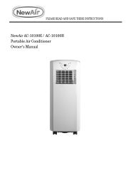
OWNER’S <strong>MANUAL</strong>Room Air Heat Pumpwith R-410A:RAH-183GHeat Controller, Inc. • 1900 Wellworth Ave. • Jackson, MI 49203 • (517)787-2100 • www.heatcontroller.com
Heat Controller, Inc. Room Air Heat Pump with R-410A Owner’s ManualContentsIntroduction............................................................. .................................................................. 11Safety Information................................................... ....................................................... 11Normal Electrical Care Requirements & Maintenance................................... .............................................. 22Electrical Normal Care Requirements.......................................... and Maintenance 23Installation General Instructions Requirements....................................... ................................................... 3. 5General Installation Operating Instructions Instructions............................... ............................................... 56Installation Operating Instructions........................................... Controls .................................................... 612Vent Before Control.......................................................... Calling Service 1415Troubleshooting....................................................When Service Is Required ........................................1516Any Questions? .......................................................... 16When Service is Required.................................... 15Through-The-Wall Installation Instructions ............. 17Any Questions....................................................... 15IntroductionRoom air conditioners cool, dehumidify, and filter air insideyour home. Heat pump models and electric offer heat both models heating offer and cooling.heating The and opening cooling. sections Opening of this sections manual of manual provides provide somebothgeneral information for for all all room room air conditioner air models. models. TheOperating Controls section describes operation of controlsfor each model. After reading the opening sections, turn tothe Operating Operating Controls Controls section section and and find find the panel the panel layout layout thatthat matches matches the model your model. of your unit.Read entire manual thoroughly before beginning installationand operation of your new room air conditioner. Be sure youhave all necessary tools and materials on hand for the job.Study illustrations to familiarize yourself with importantdetails of the installation process. Review manual for operatinginstructions.NOTE1. Mechanical experience is required to install air conditioner.2. Installation can take from 1 to 3 hours, depending oninstaller’s knowledge and skill.3. If you encounter problems during installation, call our ourconsumer information line at at (86-756) (517) 787-2100 8617555. and ask forthe If your technical problem service cannot deparment. be resolved If by your phone, problem contact cannotbe authorized resolved GREE by phone, ® brand contact servicer. an authorized Contact and servicer.will be at your expense.<strong>Comfort</strong> Zone TMRoom Air Conditioner & Heat PumpUse and Care ManualSafety InformationBe sure electrical service is adequate for chosen model of airconditioner. Complete electrical rating for unit is found onserial plate located behind front grille. Electrical outlet mustbe close enough to unit for power cord to reach without strain.Air conditioner should be the only appliance on individualcircuit.For personal safety and to avoid possible damage to applianceor home, observe all safety instructions highlighted bysymbol shown below.RECOGNIZE THIS SYMBOL AS ASAFETY PRECAUTION.After installing unit, reread instructions to ensure each stepis complete and that all parts are fastened in place. For bestresults and to minimize installation time, perform all proceduresin the order shown.WARNINGTo prevent heat related illness illness or death, or death, dodo not not use use this this device for unattended.coolingFailure of persons of an or unattended animals unable air conditioner to react tomay product result failure. in extreme Failure heat of in unattended area airintended conditioner for cooling, may result causing extreme heat related heat inillness or death of persons or animals.area intended for cooling, causing heatrelatedillness or death of persons oranimals.11
Owner’s Manual Room Air Heat Pump with R-410A Heat Controller, Inc.WARNINGHIGH TEMPERATURE STRESS HAZARDThis room air conditioner is not meant toprovide unattended cooling or life supportfor persons or animals that are unable toreact to failure of the product.The failure of an unattended air conditionermay result in extreme heat in the conditionedspace causing overheating ordeath of persons or animals.Precautions must be taken to ward off orguard against such an occurrence.UnpackingUnpackingUnpack and visually inspect the unit. Report any damage toUnpack the delivering and visually carrier immediately. inspect the If unit. your Report unit is not any damaged,tothe remove delivering and disgard carrier all immediately. packing materials. Remove On some and models discard allpacking the air conditioner material. front On and/or some models mounting the kit air hardware conditioner may be frontand/orpackedmountingseparately.kit hardware may be packed separately.Record the model, and serial serial and numbers manufacturing of your unit numbers in the space of yourunit provided. in the This space information provided is below. found on This a nameplate information visible found after ona the nameplate front of the visible air conditioner after the has front been of removed. the air conditioner The rated hasbeen voltage, removed. amperage The and rated capacity voltage, for your amperage specific and model capacity can foryour also be specific found on model this nameplate. can also be Read found the warranty on this packaged nameplate.Readwith thetheunit.warrantyRegisterpackagedyour unitwithand keepthe unit.theKeepwarrantytheandwarrantyaandcopyaofcopyyourofsalesyourreceiptsales receiptfor futureforreference.future reference.You mayYoualsomaywant to record in the space provided the date purchased andalso want to record in the space provided the date purchasedthe selling dealer.and the selling dealer.<strong>OWNER'S</strong> PRODUCT IDENTIFICATIONMODEL NUMBERSERIAL NUMBERMANUFACTURING NUMBEROwner's NameAddressCity State Zip/ /Date of PurchaseAuthorized DealerAddressCity State Zip( )Phone NumberWARNINGTo avoid death, personal injury or propertydamage due to electrical shock:• Observe all local codes and ordinances.• Disconnect electrical power to unit before servicing.• Ground appliance properly.• Check with a qualified electrician if you are notsure this appliance is properly grounded.• DO NOT ground to gas line.• DO NOT ground to cold water pipe if pipe isinterrupted by plastic, non-metallic gaskets, orother insulating (non-conducting) materials.• DO NOT modify plug on power cord. If plugdoes not fit electrical outlet, have proper outletinstalled by qualified electrician.• DO NOT have a fuse in the neutral or groundcircuit. A fuse in the neutral or ground circuitcould result in an electrical shock.• DO NOT use an extension cord with this appliance.• DO NOT use an adapter plug with this appliance.• DO NOT pinch power cord.• DO NOT REMOVE warning tag from power cord.Electrical RequirementsGrounding InstructionsThis appliance is equipped with a three-prong grounding plugfor protection against possible shock hazards. If a two-prongwall receptacle is encountered, the customer is required tocontact a qualified electrician and have the two-prong wallreceptacle replaced with a properly grounded three-prongwall receptacle in accordance with the National ElectricalCode.Room air conditioners are designed to operate according torequirements on the nameplate and as shown in Table 1.Fuse or circuit breaker ratings must be according to the fuseinstruction label and as shown in Table 1. Do not plug modelsmarked “Use on Single Outlet Circuit Only” into a circuit withanother appliance or light fixture.Receptacle WiringReceptacle wiring must be of adequate size for unit. Referto unit identification plate for exact power requirements.Minimum size of wiring, based on power requirements, is:Units up to 20 amps: 12 gauge20–30 amp units: 10 gaugeLCDI or AFCI Power CordsUnderwriters Laboratories (UL) and the National ElectricCode (NEC) now require power cords that sense currentleakage and be can able open to open the the electrical circuit to to the the unit. In the22
Heat Controller, Inc. Room Air Heat Pump with R-410A Owner’s ManualUnit Plug Receptacle Circuit Rating, VoltageType Required Breaker, Time Rating OnDelay FuseNameplateNEMA No. No. 5-15P 5-15P NEMA No. No. 5-15R 5-15R 125V-15AMP 115V 115VNEMA No. No. 6-15P 6-15P NEMA No. No. 6-15R 6-15R 250V-15AMP 230/208V rated ratedat at 12 12 amperes or orless lessNEMA No. No. 6-20P 6-20P NEMA No. No. 6-20R 6-20R 250V-20AMP 230/208V rated ratedover over 12 12 amperes,but but not not more more than than16 16 amperesNEMA No. No. 6-30P 6-30P NEMA No. No. 6-30R 6-30R 250V-30AMP 208V 208V rated rated over over16 16 amperes, but butnot not more more than than24 24 amperesevent, the unit does not operate, check the reset buttonlocated on or near the head of the power cord as part of thenormal troubleshooting procedure.Use copper wire only. Consumer’s responsibility is to provideproper and adequate receptacle wiring that conforms to allapplicable codes. All wiring should be installed by qualifiedelectrician.InstallationComplete step-by-step installation instructions are furnishedwith your unit. These instructions will be found on a separatepage included with this manual or in the mounting kitassembly. Follow these instructions carefully. Keep theseinstructions with this manual for future reference. Your unitwill be one of the following three designs:• Unit with a window mounting kitThese models are designed for mounting though anopening in a wall. These units can be adapted towindow installation by using the optional window mountingkit supplied with your unit.• Unit without a window mounting kitNo window mounting kit is supplied with the unit.These models are designed for mounting through anopening in a wall. These units can be adapted towindow installation by purchasing an optional windowmounting kit. Consult your dealer to choose the kit thatis appropriate for your model and installation.• Unit with a separate sleeveSome Builder models are designed such that the outercase and the chassis can be purchased separately.Through-the-wall installation instructions are includedwith the outer case. These models can be adapted towindow installation by purchasing an optional mountingkit.Room Heat PumpsHeat pumps work by moving heat instead of creating it. In thesummer, the cool indoor coil absorbs heat from your roomand moves it it outdoors, providing cooling. In the winter, heatpumps reverse this operation. By lowering the temperatureof the outdoor coil below the outdoor temperature, the heatpump absorbs the heat from outdoors and moves it it insideyour house. This heat transferring process is very efficient.For example, at 45°F outdoor temperature, a heat pump canprovide 2 ½ watts of heat for every watt of electricity it itconsumes.As outdoor temperatures drop, the heating capacity andefficiency of the heat pump declines. At temperatures below45°F, it it is likely that ice will form on the outdoor coil. Heatpump units are designed to operate as a heat pump aboveapproximately 40°F. Below 40°F, these units switch automaticallyfrom reverse cycle heat pump to auxiliary electricheating. No defrost is required. There is no minimumoperating temperature.Normal Care and MaintenanceWARNINGTo avoid property damage, personal injuryinjuryor death due to to electrical shock, turn turn unitfanOFF control and OFF remove and plug remove from plug wall outlet from wall beforeinspecting outlet before unit inspecting or performing unit maintenance.or performingmaintenance.Annual InspectionIt It is suggested that your unit be inspected by your dealer orservicer once a year. It It is advisable to have the outer caseremoved and the unit thoroughly cleaned.Note: The life of your unit may be greatly reduced if if you if live in in aNote: The life of your unit may be greatly reduced if you livecorrosive environment such as an oceanside location with saltyin a salt air or other corrosive type environment. Under theseair. Under these conditions, the unit should be removed from itsconditions, the unit should be removed from its case andcase and completely cleaned at least once a year. At that timecompletely cleaned at least once a year. At that time anyany scratches or blistersscratches or blisters onon thethe paintedpainted surfacessurfaces in should beshould sanded and repainted. Placing an algaecide tablet in the outdoorbesanded and repainted. Placing is an algaecide in tablet in side of the unit’s basepan is suggested in humid areas where theoutdoor side of is the unit’s basepan is suggested in algae formation is common.humidareas where algae formation is common.33
Owner’s Manual Room Air Heat Pump with R-410A Heat Controller, Inc.Front Grille and Filter RemovalThe front contains a removable grille that provides easyaccess to the air filter. To clean the filter use one of thefollowing methods for filter removal:METHOD ONEGrasp filter handle and slide filter out of unit.Optional Air Filter InstallationRemove air filter from plastic bag. Insert three tabson right side of filter into three slots on filter frame. Carefullybow middle of filter until two tabs on filter can be inserted intotwo slots on filter frame. Relax bow.Reinstall air filter and grille by reversing removal procedure.Front Grille and Cabinet CleaningGrille and cabinet may be cleaned with warm water and mildsoap or detergent. Cleaning and polishing compounds arenot recommended, as they may damage plastic surfaces.Air Filter CleaningA dirty air filter reduces operating efficiency of unit. Filtershould be inspected at least once every week during operation.Clean filter with vacuum cleaner or wash in warm waterand mild detergent. Filter should be thoroughly dried beforereplacing in unit. Do not operate unit without filter in place.Fan Motor CareThe fan motor is permanently lubricated for long life. There isno need to oil the motor.Slide-out Chassis Removal from Outer Case1. Remove front grille by sliding grille to left and pulling out.2. Remove air filter by sliding to left.3. Remove four screws holding plastic front to unit andremove front.4. If the unit has a screw holding the basepan clip to thechassis, remove the screw.CAUTIONTo reduce the risk of of personal injury, injury be besure to have sufficient help help when when moving movingyour unit. A A room room air air conditioner conditioner can can beexcessivley heavy.weigh between 70 and 240 pounds.5. Using basepan handle, pull chassis straight out, slowlyand evenly, until approximately 9-12 inches extends44
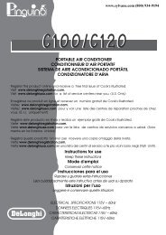
Heat Controller, Inc. Room Air Heat Pump with R-410A Owner’s Manualfrom outer case. Use both hands to grasp basepan andpull remaining chassis from outer case.PLASTIC FRONTBASEPANCLIPCHASSISNOTE: Basepan clip is shipped in plastic bag with mountingscrew and condensate drain cup. Install clip after reinsertingchassis into outer case to prevent accidental chassis removal.General Operating InstructionsWhile operation of all units is similar, controls vary slightlyfrom model to model. Operating Controls section showscontrol panel of unit purchased and gives detailed informationabout operation of controls.Drain Cup Installation and Use (on some models)Your air conditioner uses a system where the water removedfrom the indoor air (condensate) is channeled to the outdoorside of the unit. The outdoor fan blade has a “slinger” ringattached to it that dips into the water and slings the water ontothe outdoor coil surface. This is the sound of water you hearduring normal operation. The water quickly evaporates onthis warm surface and improves the efficiency of your airconditioner. In normal conditions the unit can evaporate thewater as fast as it is removed from the indoor air.However, in very humid conditions excess amounts of watermay drip off the unit chassis. If this proves to be a problem,install the condensate drain cup included with the unit toroute excess water where it would not be a problem (seeillustration below).To install, remove the unit chassis from the outer case. Insertthe condensate drain cup through the recessed ½” hole onthe right side bottom flange of the outer case. Once inserted,place a ½” diameter hose or tube on the drain cup bottomspout. The hose allows you to route where you want theexcess water to go. Reinsert the unit chassis into the outercase. The unit basepan overflow hole will be positioneddirectly above the drain cup and will catch any water thatmight run out.Initial Start-Up and CoolingSelect the highest fan speed and set temperature control toits coldest position. When the desired temperature isreached, slowly move the temperature control toward awarmer setting until the compressor shuts off. The thermostatwill then cycle the compressor on and off to maintain thisselected temperature. Adjust the fan speed for desired aircirculation.CondensateDrain CupOuter CaseBAFFLES1/2" DiameterHoseINDOORGRILLEOUTDOORLOUVERSChanging Airflow Direction BafflesAirflow on unit may be diverted left or right from center bybaffles. Upward and downward air discharge is provided bytilting louvers. Adjust baffles and tilt louvers for desiredairflow pattern.Airflow Around UnitCheck the indoor grille and outdoor louvers for obstructions toairflow. Do not block the airflow to and from the unit. If air isobstructed and/or deflected back into the unit, the airconditioner’s compressor may cycle on and off rapidly. Thiscould damage your unit.Switchover Thermostat ControlEmergency heat switch overrides heat pump (compressor)and starts auxiliary electrical heater. When switch is ON,heat pump is locked out.• Use emergency switch only when heat pump fails toprovide adequate heat. Cause of heat pump malfunctionshould be determined by authorized servicer. Costof operating unit will increase when emergency heatswitch is engaged.To access and engage emergency switch:1. Remove front grille, air filter, and plastic front, as describedin Installation Instructions.2. Remove basepan clip.3. Slide chassis out of case about two inches.4. Locate access hole for emergency switch above label onright front of control box.5. To start emergency heat, insert flathead screwdriver intoslot and turn counterclockwise until switch-stop is reached.6. Return chassis to case.7. Replace basepan clip, plastic front, air filter, and frontgrille.55
IMPORTANT Save theseinstructions for local inspector's use.IMPORTANTObserve allOwner’s Manual governing codes and ordinances. Room Air Heat Pump with R-410A Heat Controller, Inc.Note to Installer Be sure to leave theseinstructions with the Consumer.TOOLS YOU WILL NEEDNote to Consumer Keep theseInstallation6Air Conditionerinstructions for future reference.Skill level Installation of this appliancerequires basic mechanical skills.Adjustable wrenchInstructionsCompletion time Approximately 1 hourWe recommend that two people installthis product.Proper Question? installation Consumer is the information responsibility line (86-756) 517-787-2100 8617555(Customer Service Center)of the installer.Phillips head screwdriver Flat-blade screwdriverProduct failure due to improper installationis not BEFORE covered under YOU the BEGIN Warranty.CAUTION:Installation Air ConditionerDo not, under any circumstances, cut orremove the Pencil third (ground) prong Ruler orfrom tape measure theRead these instructions completelyandInstructionsELECTRICAL REQUIREMENTS power cord.carefully.Do not change the plug on the power cordIMPORTANT Save theseof this air conditioner.The 3-prong grounding plug minimizes thepossibility instructions Question?offor electricConsumer local inspector's shockinformationhazard. use. Iflinethe(86-756)wall8617555(Customer Aluminum house Service wiring Center)Level may present Scissors special or knifeproblems consult a qualified electrician.outlet IMPORTANTObserveyou plan to use is only a 2-prongalloutlet,it isgoverningyour responsibilitycodes andtoordinances.have it replaced witha properlyNote toBEFORE groundedInstaller BeYOU 3-prongsureBEGIN wall outlet.to leave theseCAUTION:instructions Some models with the require Consumer. 230/208-volt a.c., Power cord includes a current interrupterTOOLS Do not, under YOU WILL any circumstances, NEED cut orprotected with a time delay fuse or circuit device. A test and reset button is provided onReadNotetheseto ConsumerinstructionsKeepcompletelytheseremove the third (ground) prong from thebreaker. These models should be installed the plug case. The device should be tested on aandinstructionscarefully.for future reference.power cord.on their own single branch circuit forperiodic basis by first pressing the TEST buttonSkill level best performance Installation and of this to prevent applianceDo and not then change the RESET the plug button. If the the power TEST cord buttonrequires IMPORTANT overloading basic mechanical house Save orskills.apartment these wiring of does this not air trip conditioner. or if Adjustable the RESET wrench button will not stayCompletion instructions circuits, for time which local Approximately inspector's could cause use. a possible 1 hourAluminum engaged, discontinue house wiring use may of the present air conditioner specialfire hazard from overheating wires.We IMPORTANTObserve recommend that two people installproblems and contact consult a qualified a service qualified technician. electrician.this governing product. codes and ordinances. Proper Note to installation Installer Be is the sure responsibility to leave theseof instructions the installer. with the Consumer.TOOLSPhillips headYOUscrewdriverWILL NEEDFlat-blade screwdriver Product Note to Consumer failure due Keep to improper theseinstallationis not covered under the Warranty.instructions for future reference.Skill level Installation of this appliancerequires basic mechanical skills.Completion ELECTRICAL time Approximately REQUIREMENTS 1 hourWe recommend that two people installthis product.The 3-prong grounding plug minimizes thepossibility Proper installation of electricis shock the responsibility hazard. If the walloutlet of the youinstaller.plan to use is only a 2-prong outlet,it is Product your responsibility failure due to improper to have it installation replaced witha properly is not covered grounded under 3-prong the Warranty. wall outlet.Some models require 230/208-volt a.c.,protected with a time delay fuse or circuitELECTRICAL breaker. These models REQUIREMENTSshould be installedon their own single branch circuit forbest performance and to preventThe 3-prong overloading grounding houseplug or apartment minimizes wiring thepossibility circuits, of electric which shock could cause hazard. a possible If the walloutlet you fireplan hazard to from use isoverheating only a 2-prong wires. outlet,it is your responsibility to have it replaced witha properly grounded 3-prong wall outlet.Some models require 230/208-volt a.c.,protected with a time delay fuse or circuitbreaker. These models should be installedon their own single branch circuit forbest performance and to preventoverloading house or apartment wiringcircuits, which could cause a possiblefire hazard from overheating wires.6of this air conditioner.Aluminum house wiring may present specialproblems consult a qualified electrician.Pencil Adjustable wrench Ruler or tape measureLevelPhillips head screwdriverScissors or knifeFlat-head Flat-blade screwdiverscrewdriverPower cord includes a current interrupterdevice. A test and reset button is provided onPencilRuler or tape measurethe plug case. The device should be tested on aperiodic basis by first pressing the TEST buttonand then the RESET button. If the TEST buttondoes not trip or if the RESET button will not stayengaged, discontinue Level use of the Scissors air conditioner or knifeand contact a qualified service technician.Power cord includes a current interrupterdevice. A test and reset button is provided onthe plug case. The device should be tested on aperiodic basis by first pressing the TEST buttonand then the RESET button. If the TEST buttondoes not trip or if the RESET button will not stayengaged, discontinue use of the air conditionerand contact a qualified service technician.6
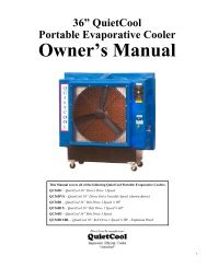
Heat Controller, Inc. Room Air Heat Pump with R-410A Owner’s ManualInstallation InstructionsPARTS INCLUDED(Appearance may vary)Windowsash sealLeftaccordionpanelTopmountingrailFoam topwindow gasketRightaccordionpanelV-support (2)Window lockingbracket (2)Bolt (2) & nuts (2)Type A (6)Type B (4) Type C (7) Type D (6)Type E (4) Type F (2)77
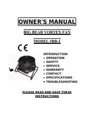
Owner’s Manual Room Air Heat Pump with R-410A Heat Controller, Inc.Installation Instructions1WINDOW REQUIREMENTSThese instructions are for a standarddouble-hung window. You will need tomodify them for other types of windows.The air conditioner can be installedwithout the accordion panels if neededto fit in a narrow window. See thewindow opening dimensions. All supporting parts must be securedto firm wood, masonry or metal.The electrical outlet must be withinreach of the power cord.3REMOVE THE AIR CONDITIONERFROM THE CASERemove the locking screw and lockingA Remove the locking screw and lockingbracket from the lower frame.bracket from the lower frame. Save toreinstall later.Save to reinstall later.Remove the ground screw and save toB Remove the ground screw. Save toreinstall later.reinstall later. min.30" to 38.1"(With accordion panels)26” min.(Without accordion panels)26" min.(Without accordion panels)Remove the ground screwand save to reinstall laterSlide the air conditioner from the case byCgripping the base pan handle and pulling unitforward while bracing the case.2STORM WINDOW REQUIREMENTSA storm window frame will not allow theair conditioner to tilt toward the outside,and will keep it from draining properly.To adjust for this, attach a piece of woodto the stool.WOOD PIECES-WIDTH: 2"LENGTH: Long enough to fit inside thewindow frame.THICKNESS : To determine the thickness,place a piece of wood on the stool tomake it 1/2" higher than the top of thestorm window frame.Attach securely with nails or screwsprovided by the installer.1/2" higherthan frameStormwindowframeStoolWood4PREPARE THE WINDOWCut the window sash seal to the properlength. Peel off the backing and attach theseal to the underside of the window sash.88
Heat Controller, Inc. Room Air Heat Pump with R-410A Owner’s ManualInstallation Instructions5ABPREPARE THE CASEInstall the top mounting rail with 4 type Bscrews from the inside of the case.Insert the frames for the accordion panelsinto the top mounting rail and the bottomframe guides. Attach the accordion panelsto the side of the case using 3 type A screwson each side.Note: When attaching the accordion panels,make sure to only screw the inner panelsto the case sides.Top mounting rail6AINSTALL THE CASEIN THE WINDOWCarefully slide the case into the window andcenter the case. Lower the window behindthe top mounting rail. Pull the bottom of thecase forward so that the bottom mountingrail is tight against the back of the windowstool. Mount the case to the window sill using4 type E screws. Drill pilot holes, if necessary.4 type E screwsS toolBottom frame guidesBMake sure the bolts and nuts are all of theway in both the left and right V-supports.Bolt and nutCPosition the V-supports on the case bottomso that they will be near the outside wall.Attach a V-support to each side of thebottom of the case using type C screws,3 on each side.V-support99
Owner’s Manual Room Air Heat Pump with R-410A Heat Controller, Inc.Ins tallation Ins tructions6DINSTALL THE CASEIN THE WINDOW (cont.)Adjust the leveling bolts and nuts against theoutside wall so that the case has a slight tiltto the outside. Tighten nuts with an adjustablewrench. Use a level; about a 1/2 bubble willbe the correct case slant to the outside.7 INSTALL SUPPORT BRACKETSAND TOP THE WINDOW FOAM TOP FOAM WINDOW GASKETGAS K ETAttach the support brackets with twoAtype D screws, one on each side.EUse a wood block (obtained locally) betweenthe leveling bolts and the wall if the wall isweak or if the weight of the air conditionerfalls between the studs in the wall.the foam top window gasket to theB Cut the top window foam gasket to the windowwidth. window width.the foam between the glass and theC Stuff the foam between the glass and the windowto window prevent to air prevent from getting air into andthe insects room. fromgetting into the room.FExtend the left and right accordion panelsto the vertical window sashes. Drill pilotholes and attach the top and bottom cornerswith 4 type D screws.Top mounting railType DscrewType DscrewType DscrewType Dscrew1010
Heat Controller, Inc. Room Air Heat Pump with R-410A Owner’s ManualIns tallation Ins tructions8ABINSTALL THE AIR AIRCONDITIONERIN THE CASESlide the airconditioner intothe case. Do notpush on thecontrols or thefinned coils.Make sure theair conditioneris firmly seated.Reinstall the locking bracket and screwremoved earlier.8 INSTALL THE AIR CONDITIONERIN THE CASE (cont.)G Pull the coiled power cord from its shippedposition in the air discharge area. Attachthe front grille frame to the case by insertingthe tabs on the grille frame into the slotson the front top of the case. Push the grilleframe in. And install the 2 type F screws at bottomleft and right side of front panel.CReconnect the ground wire to the airconditioner using the screw removed earlier.IMPORTANT: The ground wire must bereinstalled to ensure a proper ground.HGuide the lever carefullythrough the grille frameas you push it in.Secure the front grille frame to the casewith one type C screw.DERemove the front grille from its box andremove the shipping tape.Grasp the inlet grille at the bottom cornersand pull it forward. Unhook it from its tophinges and set it aside.IReinstall the filter.FUsing the tab, pull up slightly on the filterto release it and pull it down and out.JReinstall the inlet grille. Connect power.1111
Owner’s Manual Room Air Heat Pump with R-410A Heat Controller, Inc.Owner’s Manual Room Air Heat Pump with R-410A Heat Controller, Inc.Operating Controls(For Electronic units)your air conditioner properly helps you to obtain thebestOperating possible results. Controls(For Electronic units)Operating This section Controls(For explains proper air conditioner Electronic operation. units)IMPORTANT: Operating your air conditioner properly helps you to obtain theOperating your best■ If youair possibleturnconditioner results.off theproperlyair conditioner,helps youwaittoatobtainleastthe3 minutesbest possible OperatingbeforeThis results. section Controls(Forturningexplainsit back on.properThisairpreventsconditioner Electronicthe airoperation. units)conditionerThis section from explains IMPORTANT: blowing proper a fuse air or conditioner tripping a operation. circuit breaker.Operating yourIMPORTANT: ■ If youairturnconditioneroff theproperlyair conditioner,helps youwaittoatobtainleastthe3 minutesbest ■ Do not try to operate your air conditioner in in the the cooling mode whenOperatingpossiblebeforeresults.turning Controls(For it back on. This prevents Electronic the air conditioner units)■ If you This turn section outside when offfrom outside explains the temperatureblowingair temperature conditioner, proper aisfusebelow air is or conditioner wait below tripping61°F at 61°F (16°C). leasta operation. circuit (16°C). 3 Do minutesbreaker.not Dotry not to try operate tobefore turning your operate air itconditioner your back air on. conditioner This in the prevents heating the heating the mode air conditionerwhen mode outside when outside temperatureIMPORTANT:from blowing Operating is ■temperature over Do a 86°F not fuse your try (30°C). airis or to conditionerover tripping operate86°F Otherwise, your(30°C). a circuit properly air the conditionerThe breaker. inside helpsinside evaporator in you in the the obtain cooling coil the modecoil will freeze when■ If best up, youwill and possible turn outside whenfreeze the off outsideup, air the temperature results.and conditioner air temperature conditioner, isthe air conditioner will below isoperate wait below 61°F at 61°F (16°C).will properly. least (16°C). 3 Do minutes not Dotry not to try operate to■ Do not before try to operate your air the cooling operate mode properly.This section turning your operate air explains itconditioner your back air on. conditioner proper This in the prevents air heating conditioner the heating the mode air conditionerwhen operation. mode outside when outside temperaturewhen outside from blowing is is below 61°F (16°C). Do not try NOTE: In temperature over a 86°F fuse (30°C).the event of is ora over trippingpower 86°F Otherwise,failure, (30°C). a circuit theyour The breaker. insideair inside evaporatorconditioner coilwill coil will freezeIMPORTANT:operate your air up, conditioner in the heating mode when outsideoperate at will andthe freeze theprevious up, air and conditionersettings the air conditioner will operatewhen will properly.■ Do not try to operate your air conditioner in the cooling power operate mode is properly.■restored.temperatureIfisyouoverturn86°Foff the(30°C).air conditioner,The inside evaporatorwait at leastcoil3 minuteswhenwill freeze NOTE: beforeoutsideup, and Inturning temperaturethe the air event it backisconditioner of a on.belowpower This61°Fwill failure, prevents(16°C).operate your theDoproperly. air airnot conditionertry towilloperateoperate from your blowing air conditionerat the previous a fuse in or thesettings tripping heatingwhen a mode circuit whenthe breaker. outsidepower is restored.temperature is over 86°F (30°C). The inside evaporator coilNOTE: In the ■will event of a power failure, your air conditioner willLights freezeDo notnext up,tryandto operate the air touch conditioneryour air conditionerpads will on operatein thethe air properly.cooling modeconditioneroperate at the when previous outside settings temperature when is below the power 61°F (16°C). is restored. Do not try toNOTE: control Inoperate the eventLights panel your of airnext indicate a power conditioner failure,to the touch the in selected the your heating air conditionerpads on the settings. mode when will outsideair conditioneroperate at temperature the previous is over settings 86°F (30°C). when the The power inside is evaporator restored. coilThe will display control freeze shows up, panel and the indicate the set air temperature conditioner the selected will operate Light settings. indicates properly. the unitLights next when to in the Heat/Cool/Energy touch pads on Saver the mode. air conditioneris in the temperature orNOTE: Shows In The time the display event remaining shows of a on power the the set delay temperature failure, timer. yourdelay air Light conditioner time indicates Set mode. the will unitcontrol Lights operate panel Shows next when indicate the to the room the previous Heat/Cool/Energy temperature touch the selected pads settings when on Saver when settings. the mode. air the conditioner power is in the temperature is restored.Shows time remaining on the delay timer. delay time Set mode.The display control FanshowsOnly panel modeShows the indicate the set room temperature the selected when settings.Light indicates Light the unit indicates the unitwhen in The Heat/Cool/Energy displayFanshowsOnly modethe Saver set is temperaturein mode. the temperature is in the or temperature orPOWERShows time Lights remaining next on to the delay touch Light timer. pads indicates Set delay Lightmode. on the time the unit indicates Set air mode. the unitwhen in Heat/Cool/Energy Saver conditioner +is in mode. the temperature is in the or temperature Set orShows the room temperature POWERShows control time remaining panel indicate on when the delayinthe timer. selected Set delay mode. time Set mode.settings. TEMP/TIMER +AUTOHEATSetFan Only Shows modethe room temperature when inHIGHCOOLTEMP/TIMERThe display showsAUTOthe set temperatureHEATFan Only modeMED HIGH ENERGYCOOLSAVERLight indicates the unitwhen POWER in Heat/Cool/Energy Saver mode. is in the temperature orLOW MED FAN ONLY ENERGY SAVERShows time remaining on the delay+Set timer. delay time Set mode.POWER LOWFAN ONLYShows the room FANtemperature SWINGTIMERSPEEDMODE when in+Set TEMP/TIMERAUTOHEAT1-24 HRFan Only modeFANMODE SWING TEMP/TIMER TIMERHIGH AUTOMED HIGHMEDLOW POWER ENERGY SAVERFAN ONLYLight indicates Light indicates theLOWFAN ONLYFANSWING Light is on. indicates Setdelay Light TIMER timer indicates is set. theSPEEDMODESWING is on.AUTOHEAT 1-24 .5-24 delay HRtimer TEMP/TIMERFANis set.SPEEDMODE0.5 TIMERSWING1-24 .5-24 HRDelay 1–24hrDelay timerDecreaseDelay Mode 1–24hr selectDelay 1–24hrDelay Fan timer speedDelay timerDelay 0.5–24hrDecrease DecreaseDecreaseTemperatureDelay Mode select timerMode selectset IncreaseDecreaseFan and speed DecreaseFan speed Mode DecreaselectDecreaseTemperatureset IncreaseTemperature Fan speedand Decreaseset Increase Decreaseand Decrease Temperatureset Increaseand DecreaseSPEED COOLHEATENERGY COOL SAVERAirHIGHAir Conditioner Conditioner ControlsCOOL ControlsMEDLOWFANSPEEDENERGY SAVERFAN ONLYRemote ControlRemote ControlRemote ControlRemote Control-Light indicatesLight Light indicates indicates the theSWING MODE is on. delay delay timer SWING timer is set. is set.Air Air Conditioner ControlsAir Conditioner ControlsLight indicates---1-24 HR+-Light indicates theTIMER1-24 HRDelay timer IncreaseSwingDelay timer Auto Increase Fan onDelay timer IncreaseSwing DelayFan speedtimer IncreaseIncreaseSwingAuto Fan Unit on power on/offAuto Fan onFan speed IncreaseFan speed Auto Increase Fan onUnit power on/offUnit power Fan on/off speed IncreaseUnit power on/off121212 1212 1212ControlsPower PadControlsControls Turns air conditioner on and off.Power PadControls Power Turns Pad air conditioner on and off.Turns air conditioner on and off.DisplayPower Pad Shows the set temperature when in Heat/Turns Controls air Cool/Energy conditioner on Saver and mode. off.DisplayShows timeShowsremainingthe set temperatureon the delaywhentimer.in Heat/ShowsDisplay Power Cool/Energy the Pad room temperature Saver mode. when Shows in Fan time OnlyShows Turns remainingthe modes. air set conditioner temperature The Set the light on delaywhen and will off. turn timer.in Heat/ on while ShowsDisplay Cool/Energy the setting. room Saver temperature mode. when Shows in time Fan OnlyShows remaining the modes. set on temperature The the Set delay light when will timer. turn in Heat/ on Shows whileCool/Energy the room setting. temperature Saver mode. when Shows in Fan time OnlyTemp Increase ▲ /Decrease ▼ Padsremaining modes. Display The on Set the light delay will turn timer. on while Showssetting. the room Use temperature to set temperature when in Fan Only when in HeatShows the set temperature when in Heat/modes. TheCool/Energy (on Set some lightSaver models)/Cool/Energy will turn on whilemode. Shows time Saversetting.remaining The Set on light the will delay turn timer. on while Shows setting.the room Press temperature Increase(+) when and in Fan Decrease Only (-) Padsmodes. The Set light will turn on whilesetting. Temp at the Increase same time /Decrease for 3 seconds,Temperature PadsUsedisplay to set temperature will changewhen when betweenin Heat/Cool/Energyin Heat(on o ÑF some and o C.models)/Cool/Energy Saver. The SET light will Saver turn mode. on while The setting. Set lightTemp Increase /Decrease Padswill turn on while setting.Temp Use to Increase Timer/Delay set temperature /Decrease Increase when in Pads Heat(on (+) /Decrease some (Æ-)PadsUse models)/Cool/Energy to set Delay temperature Timer Increase Saver when mode. in Heat(on (+) The /Decrease Set some light (Æ-)Padsmodels)/Cool/Energy will turn Each on while touch setting. Saver of the mode. Increase The Set / Decrease light will turn Temp Each pads on Increase while touch on the setting. of unit the /Decrease or Increase the Increase / Pads Decrease + / Decrease –Delay Use Timer pads to set on on Increase temperature the the unit remote or the (+) when control Increase /Decrease in will Heat(on + / Decrease set the some (Æ-)Pads delay –Delay Timer pads time on Increasewhen the remote (+)using the control /Decrease Delay will 1–24hr 0.5-24hr set the (Æ-)Padsmodels)/Cool/Energy Saver mode. The Set timer delay light .Each will touch time The turn when of Set on the while light using Increase setting. will the turn Delay / on Decrease 1–24hr .5-24hr while timer setting. ( ).Each pads on touch The the of Set unit the light or Increase the will Increase turn / on Decrease + while / Decrease setting. –padspads Delay onontheFan the Timer unitSpeed remoteor Increase thePads controlIncrease will (+) + / set /Decrease the delay– (Æ-)Padspads ontime when Fan theusing Speed remotethe Pads control will set the delayDelay 1–24hr timer ( ).time whenThe SetUse usinglight willset the Delayturnfan 1–24hronspeed timerwhiletosetting.Low, ( ).Each Med, HighUse touch set of the the fan Increase speed to / Low, Decrease Med, The Setor lightHighor AutoAuto willonon turnthethe onunit.unit. whileNOTE:NOTE: setting.pads on the unit or the Increase On + On / Decrease thetheremoteremote –pads use the fan speed Increase + /control, the use remote the fan control speed will Increase set the delay + /Fan Speed time Decrease when Pads using –– pads pads the to Delay to set set the 1–24hr the fan timer fan speeds speeds ( to).toUse to The set Low, Set the Med light fan fan or speed will or High. High. turn toUse Low, on Use Low, the while Med, the Auto Med, setting. Auto High pad High pad to toor Auto turn on the Auto unit. fan fan NOTE: on. on. On On the the remote remotecontrol, Fan use Speed the Pads fan fan speed Increase + / + /Decrease Mode – pads Padto to set set the the fan fan speeds toUse to set the fan speed to Low, Med, to HighLow, Med or UseorHigh. Use Use the the Auto Auto pad pad toor Auto to on to set set the the the unit. the air air conditioner air NOTE: conditioner On to the COOL, to remote COOL, to Cool, to ENERGYturn Cool, ENERGYAuto fanEnergy SAVER,fan on.control, on.use Saver,Fan FAN the OnlyFAN ONLY fan speedONLY or Only oror HEAT IncreaseHEAT or Heat mode Heat (on +mode(on / some someDecrease models) – mode. mode. pads to set the fan speeds toMode Low, PadPad Med or High. Use the Auto pad toUseUseturn toto TIMER setTIMER setAuto thethe Pads fan air conditionerPads airon. to Cool,conditioner to Cool,Energy Saver,Fan Timer/Delay Only Pads or Heat (on somemodels)EnergyTIEMR Saver,Fan ON—When Only or the Heat air conditioner (on some is off, itmodels) Mode mode.can Timer/Delay TIEMR mode. Padbe set ON—When to automatically On —When the air comethe conditioner air conditionerin 0.5 is to off, 24is itoff, itUsehours can to be setat set theits previous to air automatically conditioner tomode and come Cool,fan settings. on in 0.5 to 24TIMER Energy PadsTIMER hours Saver,FanPads at its previous Only ormode Heat (on and some fan settings.TIEMR models) ON—When mode.SWING Padthe air conditioner is off, itTIEMR can be set ON—WhenTurn SWING to automaticallyon Pad to providethe air come conditionercontinuous in 0.5side-to-sideis to off, 24itcan hours be TIMER at air setTurn its circulation. to previous Pads automatically to mode provide For and fixed comecontinuous fan side-to-side settings. on 0.5side-to-sideto air 24hours TIEMR at direction,turn air its ON—When circulation. previous mode on the For air until and conditioner fixed the fan desired side-to-side settings. is off, air it airSWING can Paddirection,turn be set to automatically is obtained,then on until come the turn on desired in it 0.5 off. to air 24Turn SWING hours on Pad todirectionat provide its previous continuousis obtained,thenmode and side-to-side fanturnsettings.air it off.Turncirculation.on to provideFor fixedcontinuousside-to-sideside-to-sideairair direction,turn circulation. SWING Padon For until fixed the side-to-side desired air airdirectiondirection,turn Turn is obtained,then to provide on until continuous turn it off.the desired side-to-side airair circulation. For fixed side-to-side airdirection is obtained,then turn it off.direction,turn on until the desired airdirection is obtained,then turn it off.
Heat Controller, Inc. Room Air Heat Pump with R-410A Owner’s ManualTimer/Delay TIMER OFF—When OFF—When the air the conditioner air conditioner is on, is on,it can be set to automatically turn off in 0.5 to24 hours.How to set:Press the TIMER0.5 1–24hr -24hr pad on the unit orTIMERtheDELAY0.5-24HR pad on the remote control. Eachtouch of the Increase / Decrease pads on theunit or the Increase + / Decrease – pads onthe remote control will set the timer in0.5 hour or 1 hour intervals (the intervals is0.5 hour as the delay timer below 10 hours;the intervals is 1 hour as the delay timer above10 hours ). The Set light will turn on while setting.To review the remaining time on the TIMER0.5 1–24hr -24hr timer, press the TIMER0.5 1–24hr -24hr pad on theTIMERunit or theDELAY0.5-24HR pad on the remote control.Use the Increase / Decrease pads on the unitor the Increase + / Decrease – pads on theremote control to set a new time if desired.To cancel the timer, press the TIMER 0.5-24hr 1–24hr paduntil the light on theTIMER 0.5-24hr 1–24hr pad goes off.Remote Control To ensure proper operation, aim the remotecontrol at the signal receiver on the airconditioner. The remote control signal has a range ofup to 20 feet. Make sure nothing is between the air conditionerand the remote control that could block thesignal. Make sure batteries are freshand installedcorrectly as indicated on the remote control.Cool ModeUse the Cool mode at Low, Med, High or Auto FanSpeed for cooling. Use the Temperature Increase /Decrease pads to set the desired temperaturebetween 61°F and 86°F in 1°F increments.The compressor will cycle on and off to keepthe room at the set level of comfort.Set the thermostat at a lower number and the indoorair will become cooler. Set the thermostat at a highernumber and the indoor air will become warmer.NOTE: If the air conditioner is off and is then turned onwhile set to a Cool setting or if turned from a fan settingto a Cool setting, it may take approximately 3 minutesfor the compressor to start and cooling to begin.This time delay is required to protect the compressor.Cooling DescriptionsFor Normal Cooling—Select the Cool mode andHigh or Med fan with a middle set temperature.For Maximum Cooling—Select the Cool modeand High fan with a lower set temperature.For Quieter & Nighttime Cooling—Select theCool mode and Low fan with a middle settemperature.Energy Saver ModeControls the fan.ON—The fan will cycle on and off with thecompressor. This results in wider variations ofroom temperature and humidity. Normally usedwhen the room is unoccupied. NOTE: The fan maycontinue to run for a short time after the compressor cycles off.OFF—The fan runs all the time, while thecompressor cycles on and off.Fan Only ModeUse the Fan Only Mode at Low, Med or High fanspeed to provide air circulation and filteringwithout cooling. Since fan only settings do notprovide cooling, a Set temperature cannot beentered. The room temperature will appearin the display.NOTE: Auto Fan Speed cannot be used when in theFan Only Mode.Heat Mode (On some models)Use the Heat mode at Low, Med, High or Auto FanSpeed for heating. Use the Temperature Increase/Decrease pads to set the desired temperaturebetween 61°F and 86°F in 1°F increments.Auto Fan SpeedSet to Auto fan speed for the fan speed to automaticallyset to the speed needed to provide optimumcomfort settings with the set temperature.If the room needs more cooling, the fan speedwill automatically increase. If the room needs lesscooling, the fan speed will automatically decrease.NOTE: Auto Fan Speed cannot be used when in theFan Only Mode.Power Outage Recovery FeatureIn the case of a power outage or interruption, theunit will automatically re-start in the settings lastused after the power is restored. If the Timer/Delay0.5-24hrfeature was set, it will resume countdown. You mayneed to set a new time if desired.1313
lowingbeforeTemperature ControlSlide this control to the left for a warmer room temperature,Owner’s to the right Manual for a cooler room temperature. Room Air Heat Pump with R-410A Heat Controller, Inc.the fandehusettingthe fandehusettingthe fanhile thetting forthe fanhile thesettingVent ControlChoose one of the following two settings by sliding the ventcontrol under the appropriate marking:OPEN – Exhausts room air to the outdoors. Alsocirculates and filters room air. This position can be used toexhaust stale or smoky air. To conserve energy, it is advisedthat the Fan Control be in the Fan Only setting when usingthis feature.CLOSE – Exhaust damper is closed. Unit circulates andfilters room air. This position should be used for normalcooling operation.austing1414
Heat Controller, Inc. Room Air Heat Pump with R-410A Owner’s ManualTroubleshootingBefore Calling ServiceWARNINGTo reduce the risk of electric shock, personal injury, or death, turn the fan control to theoff position and remove the unit plug from the wall outlet before doing any inspection ormaintenance work.The following is a list of problems that are sometimes encountered when using a room air conditioner. Possible cause andsuggested remedies are given for each problem.If the problem cannot be fixed using the suggested remedies, see WHEN SERVICE IS REQUIRED section.PROBLEM POSSIBLE CAUSE SUGGESTED REMEDYUNIT WILL NOT RUN No power to unit Push reset button on power cord.Set Fan Control to any position position other other than than OFF. OFF.Make sure plug is firmly seated in outlet.Check for blown fuses, tripped circuit breakers.LITTLE OR NO COOLINGLITTLE OR NO HEATING(fan and compressor run)Fresh air/exhaust damper openObstructed indoor or outdoor airflowDirty air filtersUnit undersized for applicationSet vent to CLOSED.Remove obstruction from indoor grille or outdoor louvers.Dirty air filter. Clean or replace, as needed.Check with dealer to determine proper capacity unit for application.LITTLE OR NO COOLING Temperature Control not set properly For cooling, turn Temperature Control to cooler setting.LITTLE OR NO HEATING(only fan runs)NOISY UNITMOUNTING SUPPORT NOTINSTALLEDFROST ON INDOOR COILFROST ON OUTDOOR COIL(heat pump models only)ODORS IN COOLINGODORS IN HEATINGFront Loose panel front may on mounting be loose assemblyWeak building constructionWater hitting fan bladeUnit oversized for application:compressor cycles on and off frequentlyStorm window frame installed in windowDirty air filterNormal for low outdoor temperaturesNormal for outdoor temperatures at orbelow 45°FMold, mildew, or algae formation on wetsurfacesNormal for first time electric heater isused each seasonFor heating, turn Temperature Control to warmer setting.Tighten any loose parts.Provide additional support for unit.Normal in high humidity. Stop noise by removing drain plug oradding condensate drain cup.Check with dealer to determine proper capacity unit for application.Some models require removal of storm window frame beforeinstallation.Clean air filter by vacuuming or washing with water and mild soap.Turning Temperature Control to warmer setting reduces occurrenceand duration of frost.Call for service only if unit does not heat room and you havechecked all problems and remedies listed under LITTLE OR NOHEATING.To reduce algae growth, use algaecide tablet in base pan; removedrain plug; add condensate drain cup and hose. Thoroughly cleanunit.Caused by dust accumulation during unused months.Odor dissipates quickly with heater use.When Service Is RequiredYour room air conditioner dealer can give you the name ofCall your 866-557-1865 nearest Authorized for service Service and Center. warranty. Help Help them them givegive you prompt you prompt service service by providing: by providing:• An accurate description of problem.• Complete model, and serial, serial and number manufacturing from (P) numbersfrom plateserialplate.serial• Proof of purchase (sales receipt) upon request.Repair by unauthorized servicer that results in subsequentfailure of unit voids warranty. Warranty details are containedin warranty certificate enclosed with unit.Keep accurate records of service calls, including what wasdone, servicer’s name, and date of service.Any Questions?Most questions can be answered by your local dealer. If youhave other matters that cannot be resolved locally, or youneed additional information regarding other heating andcooling products offered by us - please call:CONSUMER Heat INFORMA Controller, TION Inc. LINECustomer or Technical Service DepartmentTel: (86-756) 8617555 (Customer Service Center)517-787-2100Web Site: http://www.gree.com.cn1715
Owner’s Manual Room Air Heat Pump with R-410A Heat Controller, Inc.This Page WAS Left INTENTIONALLY Blank16
Heat Controller, Inc. Room Air Heat Pump with R-410A Owner’s ManualThis Page WAS Left INTENTIONALLY Blank17
07/2010 04/200966129905195