OWNER'S MANUAL - Comfort-Aire
OWNER'S MANUAL - Comfort-Aire
OWNER'S MANUAL - Comfort-Aire

You also want an ePaper? Increase the reach of your titles
YUMPU automatically turns print PDFs into web optimized ePapers that Google loves.
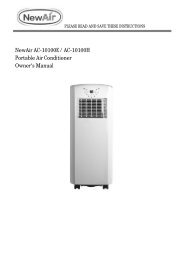
OWNER’S <strong>MANUAL</strong>Room Air Heat Pumpwith R-410A:RAH-123GHeat Controller, Inc. • 1900 Wellworth Ave. • Jackson, MI 49203 • (517)787-2100 • www.heatcontroller.com
AUTOHIGHMEdLOWFANSP EdHEAT-Owner’s Manual Room Air Heat Pump with R-410A Heat Controller, Inc.ContentsRoom Air Conditioner & Heat PumpUse and Care ManualIntroduction............................................................. .................................................................. 1Safety Information................................................... ....................................................... 1NormalNormalCareCare& Maintenance................................... ......................................3Installation Requirements ........................................... Installation Requirements....................................... 5Electrical Requirements .............................................. Electrical Requirements.......................................... 6Installation Instructions ............................................... Installation Instructions........................................... 8Through-The -Wall Cabinet Instructions .....................10General Instructions...............................................11Complete Instructions ...............................................12Operating Controls................................................ 12General Instructions .................................................. 13Troubleshooting.................................................... 14Operating Controls .................................................... 14When Service is Required.................................... 14Before Calling Services...............................................17Any Questions....................................................... 14When Service Is Required.... ...................................... 17Any Questions? ........................................................... 17Through-The -Wall Installations Instructions............ 18IntroductionRoom air conditioners cool, dehumidify, and filter air insideyour home. Heat pump models and electric offer heat both models heating offer and cooling.The and opening cooling. sections Opening of this sections manual of manual provides provide somegeneral information for all all room room air air conditioner models. models. TheOperating Controls section describes operation of controlsfor each model. After reading the opening sections, turn tobothheatingOperating the Operating Controls Controls section section and and find the find panel the panel layout layout thatmatches that matches the model your model. of your unit.Read entire manual thoroughly before beginning installationand operation of your new room air conditioner. Be sure youhave all necessary tools and materials on hand for the job.Study illustrations to familiarize yourself with importantdetails of the installation process. Review manual for operatinginstructions.NOTE1. Mechanical experience is required to install air conditioner.2. Installation can take from 1 to 3 hours, depending oninstaller’s knowledge and skill.3. If you encounter problems during installation, call ourconsumer information line at (86-756) (517) 787-2100 8617555. and ask forthe If your technical problem service cannot deparment. be resolved If your by phone, problem contact cannotbe authorized resolved GREE by phone, ® brand contact servicer. an authorized Contact and servicer.will be at your expense.Safety InformationBe sure electrical service is adequate for chosen model of airconditioner. Complete electrical rating for unit is found onserial plate located behind front grille. Electrical outlet mustbe close enough to unit for power cord to reach without strain.Air conditioner should be the only appliance on individualcircuit.For personal safety and to avoid possible damage to applianceor home, observe all safety instructions highlighted bysymbol shown below.RECOGNIZE THIS SYMBOL AS ASAFETY PRECAUTION.After installing unit, reread instructions to ensure each stepis complete and that all parts are fastened in place. For bestresults and to minimize installation time, perform all proceduresin the order shown.POWERC OLENERGY SAVERFAN ONLYMOdETEMP/TIMERSet +TIMER1-24 HR11
Heat Controller, Inc. Room Air Heat Pump with R-410A Owner’s ManualWARNINGTo prevent heat related illness illness or death, or death, donot do not use use this this device for unattended.coolingof Failure persons of an or unattended animals unable air conditioner to react toproduct may result failure. in extreme Failure heat of in unattended area airconditioner intended for cooling, may result causing extreme heat related heat inareaillnessintendedor deathforof personscooling,orcausinganimals.heatrelatedillness or death of persons oranimals.WARNINGHIGH TEMPERATURE STRESS HAZARDThis room air conditioner is not meant toprovide unattended cooling or life supportfor persons or animals that are unable toreact to failure of the product.The failure of an unattended air conditionermay result in extreme heat in the conditionedspace causing overheating ordeath of persons or animals.Precautions must be taken to ward off orguard against such an occurrence.UnpackingUnpack and and visually visually inspect inspect the the unit. unit. Report Report any damage any damage to tothe delivering carrier carrier immediately. immediately. If your Remove unit is not and damaged, discard allremove packing and material. disgard all packing materials.WARNINGDo NOT operate unit with shipping foamblocks in place. Always remove prior torunning unit.On some models the air conditioner front and/or mounting kithardware may be packed separately.Record the model, and serial and numbers manufacturing of your unit numbers in the space of yourunit provided. in the This space information provided is below. found on This a nameplate information visible found after ona the nameplate front of the visible air conditioner after the has front been of removed. the air conditioner The rated hasbeen voltage, removed. amperage The and rated capacity voltage, for your amperage specific and model capacity can foryour also be specific found on model this nameplate. can also Read be found the warranty on this packaged nameplate.Read with the the unit. warranty Register packaged your unit with and keep the unit. the warranty Keep the and warranty aand copy a of copy your of sales your receipt sales receipt for future for reference. future reference. You may You also mayalso want want to record to record in the in space the space provided provided the date the purchased date purchased andand the selling the selling dealer. dealer.<strong>OWNER'S</strong> PRODUCT IDENTIFICATIONMOdEL NUMBERSERIAL NUMBERMANUFACTURING NUMBEROwner's NameAddressCity State Zip/ /date of PurchaseAuthorized dealerAddressCity State Zip( )Phone NumberWARNINGTo avoid death, personal injury or propertydamage due to electrical shock:• Observe all local codes and ordinances.• disconnect electrical power to unit before servicing.• Ground appliance properly.• Check with a qualified electrician if you are notsure this appliance is properly grounded.• dO NOT ground to gas line.• dO NOT ground to cold water pipe if pipe isinterrupted by plastic, non-metallic gaskets, orother insulating (non-conducting) materials.• dO NOT modify plug on power cord. If plugdoes not fit electrical outlet, have proper outletinstalled by qualified electrician.• dO NOT have a fuse in the neutral or groundcircuit. A fuse in the neutral or ground circuitcould result in an electrical shock.• dO NOT use an extension cord with this appliance.• dO NOT use an adapter plug with this appliance.• dO NOT pinch power cord.• dO NOT REMOVE warning tag from power cord.Electrical RequirementsGrounding InstructionsThis appliance is equipped with a three-prong grounding plugfor protection against possible shock hazards. If a two-prong22
Owner’s Manual Room Air Heat Pump with R-410A Heat Controller, Inc.Unit Plug Receptacle Circuit Rating, VoltageType Required Breaker, Time Rating OnDelay Fuse NameplateNEMA No. 5-15P NEMA No. 5-15R 125V-15AMP 115VNEMA No. 6-15P NEMA No. 6-15R 250V-15AMP 230/208V ratedat 12 amperes orlessNEMA No. 6-20P NEMA No. 6-20R 250V-20AMP 230/208V ratedover 12 amperes,but not more than16 amperesNEMA No. 6-30P NEMA No. 6-30R 250V-30AMP 208V rated over16 amperes, butnot more than24 ampereswall receptacle is encountered, the customer is required tocontact a qualified electrician and have the two-prong wallreceptacle replaced with a properly grounded three-prongwall receptacle in accordance with the National ElectricalCode.Room air conditioners are designed to operate according torequirements on the nameplate and as shown in Table 1.Fuse or circuit breaker ratings must be according to the fuseinstruction label and as shown in Table 1. do not plug modelsmarked “Use on Single Outlet Circuit Only” into a circuit withanother appliance or light fixture.Receptacle WiringReceptacle wiring must be of adequate size for unit. Referto unit identification plate for exact power requirements.Minimum size of wiring, based on power requirements, is:Units up to 20 amps: 12 gauge20–30 amp units: 10 gaugeLCDI or AFCI Power CordsUnderwriters Laboratories (UL) (UL) and and the the National National Electric Electric CodeCode (NEC) (NEC) now require now require power cords power that cords sense that current sense leakage current toleakage be able to and open can the open electrical the electrical circuit to circuit the unit. to In the the unit. event, In theevent, unit does the not unit operate, does check not operate, the reset check button located the reset on or button nearlocated the head on of or the near power the cord head as of part the of power the normal cord troubleshootingas part of thenormal procedure. troubleshooting procedure.Use copper wire only. Consumer’s responsibility is to provideproper and adequate receptacle wiring that conforms to allapplicable codes. All wiring should be installed by qualifiedelectrician.InstallationComplete step-by-step installation instructions are furnishedwith your unit. These instructions will be found on a separatepage included with this manual or in the mounting kitassembly. Follow these instructions carefully. Keep theseinstructions with this manual for future reference. Your unitwill be one of the following three designs:• Unit with a window mounting kitThese models are designed for mounting though anopening in a wall. These units can be adapted towindow installation by using the optional window mountingkit supplied with your unit.• Unit without a window mounting kitNo window mounting kit is supplied with the unit.These models are designed for mounting through anopening in a wall. These units can be adapted towindow installation by purchasing an optional windowmounting kit. Consult your dealer to choose the kit thatis appropriate for your model and installation.Room Heat PumpsHeat pumps work by moving heat instead of creating it. In thesummer, the cool indoor coil absorbs heat from your roomand moves it outdoors, providing cooling. In the winter, heatpumps reverse this operation. By lowering the temperatureof the outdoor coil below the outdoor temperature, the heatpump absorbs the heat from outdoors and moves it insideyour house. This heat transferring process is very efficient.For example, at 45°F outdoor temperature, a heat pump canprovide 2 ½ watts of heat for every watt of electricity itconsumes.As outdoor temperatures drop, the heating capacity andefficiency of the heat pump declines. At temperatures below45°F, it is likely that ice will form on the outdoor coil. Heatpump units are designed to operate as a heat pump aboveapproximately 40°F. Below 40°F, these units switch automaticallyfrom reverse cycle heat pump to auxiliary electricheating. No defrost is required. There is no minimumoperating temperature.Normal Care and MaintenanceCAUTION WARNINGInstalling To avoid property an air conditioner damage, personal through injury a wallrequires or death due extensive to electrical carpentry shock, and/or turn unit masonryOFF experience. and remove Thru-wall plug from installations wall outlet before performedinspecting by unit inexperienced or performing maintenance.unqualifiedindividuals can result in costly damage tohome.Annual InspectionIt is suggested that your unit be inspected by your dealer orservicer once a year. It is advisable to have the outer caseremoved and the unit thoroughly cleaned.33
Heat Controller, Inc. Room Air Heat Pump with R-410A Owner’s ManualWindow installationWindow opening measurements:■ 27" min. to 39" max. opening width.■ 16¹⁄₄" min. opening height.Electrical RequirementsWARNINGABElectrical Shock HazardPlug into a grounded 3 prong outlet.Do not remove ground prong.Do not use an adapter.Do not use an extension cord.Failure to follow these instructions can result in death,fire, or electrical shock.Through-the-wall installationThe wall opening measurements should be:■ Height: 16" plus twice the thickness of wood used to buildframe.■A. 27" min.B. 16¹⁄₄" min.Width: 22⁵⁄₈" plus twice the thickness of wood used to buildframe.ABCGround wire must be connected to ground screw located in lowerright corner of air conditioner when air conditioner is in cabinet.The electrical ratings for your air conditioner are listed on themodel and serial number label. The model and serial numberlabel is located behind the front panel on the flange below thecontrol panel area.Specific electrical requirements are listed in the chart below.Follow the requirements for the type of plug on the power supplycord.Power supplycordWiring requirements■ 115-volt (103.5 min. - 126.5 max.)■ 0-12 amps■ 15-amp time-delay fuse or circuit breaker■ Use on single outlet circuit only.A. 16"B. 22⁵⁄₈"C. Wood thicknessC¹⁄₄"(0.6 cm)■■■■230-volt (207 min. - 253 max.)0-12 amps15-amp time-delay fuse or circuit breakerUse on single outlet circuit only.■208/230-volt (198min. - 253 max.)■0-16 amps■20-amp time-delay fuse or circuit breaker■Use on single outlet circuit only.¹⁄₂"(1.3 cm)■■230-volt (207 min. - 253 max.)0-24 amps■30-amp time-delay fuse or circuit breaker■Use on single outlet circuit only.66
Owner’s Manual Room Air Heat Pump with R-410A Heat Controller, Inc.Recommended grounding methodThis air conditioner must be grounded. This air conditioner isequipped with a power supply cord having a grounded 3 prongplug. To minimize possible shock hazard, the cord must beplugged into a mating, grounded 3 prong outlet, grounded inaccordance with all local codes and ordinances. If a mating outletis not available, it is the customer's responsibility to have aproperly grounded 3 prong outlet installed by a qualified electricalinstaller.It is the customer's responsibility:■ To contact a qualified electrical installer.■ To assure that the electrical installation is adequate and inconformance with National Electrical Code, ANSI/NFPA 70 -latest edition, and all local codes and ordinances.Copies of the standards listed may be obtained from:National Fire Protection AssociationOne Batterymarch ParkQuincy, MA 02269Power Supply CordNOTE: Your unit’s device may differ from the ones shown.TESTBTESTBA. Reset buttonB. Test buttonRESETARESETAWARNINGElectrical Shock HazardPlug into a grounded 3 prong outlet.Do not remove ground prong.Do not use an adapter.Do not use an extension cord.Failure to follow these instructions can result in death,fire, or electrical shock.To test your power supply cord:1. Plug power supply cord into a grounded 3 prong outlet.2. Press RESET.3. Press TEST (listen for click; Reset button will trip and popout).4. Press and release RESET (listen for click; Reset button willlatch and remain in). The power supply cord is ready foroperation.NOTES:■ The Reset button must be pushed in for proper operation.■ The power supply cord must be replaced if it fails to trip whenthe test button is pressed or fails to reset.■ Do not use the power supply cord as an off/on switch. Thepower supply cord is designed as a protective device.■ A damaged power supply cord must be replaced with a newpower supply cord obtained from the product manufacturerand must not be repaired.■ The power supply cord contains no user serviceable parts.Opening the tamper-resistant case voids all warranty andperformance claims.This room air conditioner is equipped with a power supply cordrequired by UL. This power supply cord contains state-of-the-artelectronics that sense leakage current. If the cord is crushed, theelectronics detect leakage current and power will bedisconnected in a fraction of a second.77
Heat Controller, Inc. Room Air Heat Pump with R-410A Owner’s ManualINSTALLATION INSTRUCTIONSWARNINGExcessive Weight HazardUse two or more people to move and installair conditioner.Failure to do so can result in back or other injury.Unpacking3. Remove front panel by removed 2 phillips screws on bothbottom left right sides of front.3A: Remove both knobs from control panel.4. Pull on handle to slide air conditioner out of cabinet. Place airconditioner on cardboard.5. Remove any paking foam from inside of unit.Remove packaging materials■ Remove and dispose of/recycle all packaging materials.Remove tape and glue residue from surfaces before turningon the air conditioner. Rub a small amount of liquid dish soapover the adhesive with your fingers. Wipe with warm waterand dry.■■Do not use sharp instruments, rubbing alcohol, flammablefluids, or abrasive cleaners to remove tape or glue. Theseproducts can damage the surface of your air conditioner.Handle air conditioner gently.1. Remove air conditioner from carton and place it oncardboard.2. Remove shipping screws from both sides of cabinet.A. HandleNOTE: Do not lift, push, pull or remove any expandedpolystyrene (foam) from inside the air conditioner. It is notpacking material.AAA. Shipping screwNOTES:■ Handle air conditioner gently.■■■■Be sure your air conditioner cabinet does not fall out of theopening during installation or removal.The location where the power cord exits the air conditionershould be no more than 4 ft from a grounded 3 prong outlet.Do not block the louvers on the front panel.Do not block the louvers on the outside of the air conditioner.Window Window Installation Installation (on some models)3. Using 3 - #10 x ³⁄₈" pan-head Phillips screws, attach topchannel to air conditioner cabinet.BABBAttach Top ChannelNOTE: Attach top channel and side curtains to air conditionercabinet before placing cabinet in window.1. Locate supplied bag of screws.2. Place top channel on top of air conditioner cabinet, lining upthe 3 holes in top channel with the 3 holes on top of airconditioner cabinet.A. Top channelB. #10 x ³⁄₈" pan-head Phillips screws (3)88
Owner’s Manual Room Air Heat Pump with R-410A Heat Controller, Inc.Attach Side Curtains1. Locate provided bag of screws.2. Insert top and then bottom of right-hand curtain housing intop and bottom curtain guides on air conditioner cabinet.Attach foam adhesive sealAttach foam adhesive seal along the bottom of the curtainbottom channel.Back ViewABABA. Curtain housingB. Foam adhesive sealBottom ViewAA. Curtain housingB. Curtain guidesBA. Curtain housingB. Curtain guides3. Extend right-hand curtain outward so you may insert thefirst screw through the middle hole of the curtain. Using#10 x ¹⁄₄" pan-head Phillips screw, screw curtain to middlehole in air conditioner cabinet.NOTE: This screw is required to correctly attach curtain (topto bottom) to the air conditioner cabinet.■■■■■Install Cabinet into WindowHandle air conditioner gently.Be sure your air conditioner cabinet does not fall out of theopening during installation or removal.The location where the power cord exits the air conditionershould be no more than 4 ft from a grounded 3 prong outlet.Do not block the louvers on the front panel.Do not block the louvers on the outside of the air conditioner.1. Center empty cabinet in window. Check that lower rail of airconditioner cabinet is behind and against back side ofwindowsill. Maintain a firm hold on the air conditionercabinet. Lower window sash to hold cabinet in place.Top channel must be on inside room of window sash.Windower sashTop channell2. Measure the distance between the right-hand side of thecabinet and the inside of the window channel.3. Repeat for the left side. Adjust the cabinet until the distanceon each side is the same.4. While the right-hand curtain is still extended, insert#10 x ¹⁄₄" pan-head Phillips screws into the top and bottomslots of curtain. Screw curtain to the top and bottom holesin air conditioner cabinet.NOTE: Some curtains may have 2 slots at each end. You willbe able to see a mounting hole through the correct slot.5. Slide curtain housing into guides as far as it will go.6. Repeat above steps for left-hand curtain.A. Window sashB. Empty cabinetC. Window channelABC99
Heat Controller, Inc. Room Air Heat Pump with R-410A Owner’s Manual4. Use a ³⁄₁₆" drill bit to drill 3 starter holes 1/2" deep through the3 holes in the cabinet and into the windowsill.5. Attach cabinet to windowsill with 3 - #10 x 1/2" pan-headPhillips screws.2. Insert one of the #10 x ³⁄₄" round-head screws throughhole and into lower window sash. Insert one of the#10 x ³⁄₄" round-head screws through threaded hole in topof curtain and one in bottom of curtain.A6. Check that air conditioner cabinet is tilted 1 /2 bubble oncarpenters level to the outside so that water will run tothe outside.Attach Side Curtains to Window Frame1. Pull left-hand curtain out until it fits into window channel. Usea ³⁄₃₂" drill bit to drill a starter hole through the hole in thecurtain housing and into the lower window sash.Front ViewAA. #10 x 1/2" pan-head Phillips screwsB. WindowsillABBA. #10 x ³⁄₄" round-head screwB. Hole for #10 x ³⁄₄" round-head screw3. Repeat for right-hand curtain.Complete Window Installation1. Insert foam seal behind the top of the lower window sash andagainst the glass of the upper window.2. Place window-lock bracket on top of lower window andagainst upper window sash.3. Use a ³⁄₃₂" drill bit to drill a starter hole through the hole in thebracket and into the window sash.4. Attach window-lock bracket to window sash with#10 x ³⁄₄" round-head screw to secure window in place.ABCTop ViewBddACA. Window lock bracket(2)B. Foam sealC. Upper window glassD. #10 x 1/2" pan-head Phillips screws (3)A. Left-hand curtainB. Window channelC. #10 x ³⁄₄" round-head screwNOTES:■ Handle air conditioner gently.■ Be sure your air conditioner cabinet does not fall out of theopening during installation or removal.■ The location where the power cord exits the air conditionershould be no more than 4 ft from a grounded 3 prong outlet.Through-the-Wall Cabinet Installation■■■Do not block the louvers on the front panel.Do not block the louvers on the outside of the air conditioner.It is the customer's responsibility and obligation to have thisproduct installed by a qualified technician familiar withthrough-the-wall room air conditioner installations.1010
AUTOHIGHMEdLOWPOWERFANSP EdHEATC OLENERGY SAVERFAN ONLYMOdE-TIMER1-24 HROwner’s Manual Room Air Heat Pump with R-410A Heat Controller, Inc.General Operating InstructionsWhile operation of all units is similar, controls vary slightlyfrom model to model. Operating Controls section showscontrol panel of unit purchased and gives detailed informationabout operation of controls.Airflow Around UnitSelect the highest fan speed and set temperature control toits coldest position. When the desired temperature isreached, slowly move the temperature control toward awarmer setting until the compressor shuts off. The thermostatwill then cycle the compressor on and off to maintain thisselected temperature. Adjust the fan speed for desired aircirculation.To install, remove the unit chassis from the outer case. Insertthe condensate drain cup through the recessed ½” hole onthe back center of the outer case. Once inserted, place a ½”diameter hose or tube on the drain cup bottom spout. Thehose allows you to route where you want the excess water togo. Reinsert the unit chassis into the outer case. The unitbasepan overflow hole will be positioned directly above thedrain cup and will catch any water that might run out.Condensatedrain CupOuter CaseBAFFLESTEMP/TIMERSet +1/2" diameterHoseOUTdOORLOUVERSINdOOR IndoorGRILLE GrilleChanging Airflow Direction BafflesAirflow on unit may be diverted left or right from center bybaffles. Upward and downward air discharge is provided bytilting louvers. Adjust baffles and tilt louvers for desiredairflow pattern.Airflow Around UnitCheck the indoor grille and outdoor louvers for obstructionsto airflow. do not block the airflow to and from the unit. If airis obstructed and/or deflected back into the unit, the airconditioner’s compressor may cycle on and off rapidly. Thiscould damage your unit.Drain Cup Installation and UseYour air conditioner uses a system where the water removedfrom the indoor air (condensate) is channeled to the outdoorside of the unit. The outdoor fan blade has a “slinger” ringattached to it that dips into the water and slings the wateronto the outdoor coil surface. This is the sound of water youhear during normal operation. The water quickly evaporateson this warm surface and improves the efficiency of your airconditioner. In normal conditions the unit can evaporate thewater as fast as it is removed from the indoor air.However, in very humid conditions excess amounts of watermay drip off the unit chassis. If this proves to be a problem,install the condensate drain cup included with the unit toroute excess water where it would not be a problem (seeillustration).Switchover Thermostat ControlEmergency heat switch overrides heat pump (compressor)and starts auxiliary electrical heater. When switch is ON,heat pump is locked out.• Use emergency switch only when heat pump fails toprovide adequate heat. Cause of heat pump malfunctionshould be determined by authorized servicer. Costof operating unit will increase when emergency heatswitch is engaged.Only for Qualified Service PersonnelTo access and engage emergency switch:• Unplug unit.1. Remove front grille, air filter, and plastic front, as describedin Installation Instructions.2. Slide chassis out of case about two inches.3. Locate access hole for emergency switch above label onright front of control box.4. Remove control panel for access.5. Remove outdoor thermostat from control box and locate"flat head" adjustment screw on back of thermostat.6. To start emergency heat, insert flathead screwdriver intoslot and turncounterclockwiseuntil switch-stop is reached.7. Return chassis to case.8. Re-install lthermostat and mount control panel door.9. Replace plastic front, air filter, and frontgrille.1311
Heat Controller, Inc. Room Air Heat Pump with R-410A Owner’s ManualOperating Controls(For Electronic units) units)Operating your air conditioner properly helps you to obtain thebest possible results.This section explains proper air conditioner operation.IMPORTANT:■If you turn off the air conditioner, wait at least 3 minutesbefore turning it back on. This prevents the air conditionerfrom blowing a fuse or tripping a circuit breaker.■ Do do not try to operate your air conditioner in in the the cooling mode modewhen outside temperature is is below 61°F (16°C). do Do not not try trytoto operate operate your your air air conditioner conditioner in the in heating the heating mode mode when whenoutsideoutside temperature temperature is over 86°F is over (30°C). 86°F The (30°C). inside Otherwise, evaporator thecoilinside evaporator coil will freeze up, and the air conditionerwill freeze up, and the air conditioner will operate properly.will operate properly.NOTE: In the event of a power failure, your air conditioner willoperate at the previous settings when the power is restored.ControlsPower PadTurns air conditioner on on and off. off.DisplayShows Display the set temperature when in Heat/Cool/Energy Shows the set Saver temperature mode. when Shows in timeremaining Heat/Cool/Energy on the Saver delay mode.Shows timer. Showsthe time room remaining temperature on the when delay in timer. Fan OnlyShows modes. the The room Set light temperature will turn when on whilesetting.Fan Only mode. The Set light willturn on while setting.Lights next to the touch pads on the air conditionercontrol panel indicate the selected settings.The display shows the set temperaturewhen in Heat/Cool/Energy Saver mode.Shows time remaining on the delay timer.Shows the room temperature when inThe display shows the set temperature whenin Heat/Cool/Energy Saver mode. Shows timeremaining on the delay timer. Shows the roomtemperature when in Fan Only mode.Delay 0.5-24hr 1–24hrDelay timerDecreaseMode selectFan speedDecreaseTemperatureset Increaseand DecreasePOWER PowerAUTO AutoHIGHHighMEdMedLOWLowFAN FanSPEEd SpeedSetHeatHEATCool COOLEnergyENERGYSaverSAVERFAN ONLYFan OnlyMOdE ModeLight indicatesSWING is on.Air Conditioner ControlsRemote ControlLight indicates the unitis in the temperature ordelay time Set mode.+SetTemp / Delay TEMP/TIMER-SWING Delay TIMER0.5-24 HR1-24hrLight indicates thedelay timer is set.Delay timer IncreaseSwingAuto Fan onFan speed IncreaseUnit power on/off14 12Temp Increase ▲ /Decrease ▼ PadsUse to set temperature when in HeatTemp (on some Increase models)/Cool/Energy /Decrease Pads SaverUse The to Set set light temperature will turn when on while in Heat(on setting. somemodels)/Cool/Energy Saver mode. The Set lightPress Increase(+) and Decrease (-) Padswill turn on while setting.at the same time for 3 seconds,TemperatureDelay display Timer will Increase change between (+) /Decrease o ÑF and o C. (Æ-)PadsEach touch of the Increase / Decrease Timer/DelayIncrease (+) /Decrease pads on the unit or the Increase + / Decrease –pads (Æ-)Pads on the remote control will set the delaytime Each when touch using of the the Increase Delay 1–24hr / Decrease timer ( ).The pads Set on the light unit will or turn the Increase on while + / setting. Decrease –pads on the remote control will set the delayFan time Speed when using Padsthe Delay 0.5–24hr timer .The Set light will turn on while setting.Use to set the fan speed to Low, Med, HighorFanAutoSpeedon thePadsunit. NOTE: On the remotecontrol, use the fan speed Increase + /Decrease Use to set – the pads fan to speed set the to fan Low, speeds Med, High toLow, or Auto Med on or the High. unit. Use NOTE: the On Autothe pad remote toturn control, Auto use fan the on. fan speed Increase + /Decrease – pads to set the fan speeds toLow, Med or High. Use the Auto pad toMode Padturn Auto fan on.Use to set the air conditioner to Cool,Energy Saver,Fan Only or Heat (on somemodels) Mode Pad mode.Use to set the air conditioner to Cool,TIMER EnergyPadsSaver,Fan Only or Heat (on somemodels) mode.TIEMR ON—When the air conditioner is off, itcan Timer/Delay be Pads set to Pads automatically come on in 0.5 to 24hours at its previous mode and fan settings.Timer/Delay ON—When On —When the air the conditioner air conditioner is off, is it off, itcan SWING be set Pad to automatically come on in 0.5 to24 Turn hours on at to its provide previous continuous mode and side-to-side fan settings.air circulation. For fixed side-to-side airdirection,turn on until the desired airdirection is obtained,then turn it off.12
Owner’s Manual Room Air Heat Pump with R-410A Heat Controller, Inc.Timer/Delay OFF—When OFF—When the air conditioner the air conditioner is on, is on,it can be set to automatically turn off in 0.5to 24 hours.How to set:Press the Timer Delay 0.5 –24hr pad on the unit orTIMERtheDELAY0.5-24HR pad on the remote control. Eachtouch of the Increase / Decrease pads on theunit or the Increase + / Decrease – pads onthe remote control will set the timer in0.5 hour or 1hour intervals(the intervals is0.5 hour as the delay timer below 10 hours;the intervals is 1 hour as the delay timerabove 10 hours) The Set light will turn onwhile setting.To review the remaining time on the Timer Delay0.5 –24hr timer, press the Timer Delay 0.5–24hr pad on theTIMERunit or theDELAY0.5-24HR pad on the remote control.Use the Increase / Decrease pads on the unitor the Increase + / Decrease – pads on theremote control to set a new time if desired.To cancel the timer, press the Timer Delay 0.5–24hr paduntil the light on the Timer Delay 0.5–24hr pad goes off.Remote Control To ensure proper operation, aim the remotecontrol at the signal receiver on the airconditioner. The remote control signal has a range ofup to 20 feet. Make sure nothing is between the air conditionerand the remote control that could block thesignal. Make sure batteries are fresh and installedcorrectly as indicated on the remote control.Cool ModeUse the Cool mode at Low, Med, High or Auto FanSpeed for cooling. Use the Temperature Increase /Decrease pads to set the desired temperaturebetween 61°F and 86°F in 1°F increments.The compressor will cycle on and off to keep theroom at the set level of comfort. Set the thermostatat a lower number and the indoor air will becomecooler. Set the thermostat at a higher number andthe indoor air will become warmer.NOTE: If the air conditioner is off and is then turned onwhile set to a Cool setting or if turned from a fan settingto a Cool setting, it may take approximately 3 minutesfor the compressor to start and cooling to begin.This time delay is required to protect the compressor.Cooling DescriptionsFor Normal Cooling—Select the Cool mode andHigh or Med fan with a middle set temperature.For Maximum Cooling—Select the Cool modeand High fan with a lower set temperature.For Quieter & Nighttime Cooling—Select theCool mode and Low fan with a middle settemperature.Energy Saver ModeControls the fan.ON—The fan will cycle on and off with thecompressor. This results in wider variations ofroom temperature and humidity. Normally usedwhen the room is unoccupied. NOTE: The fan maycontinue to run for a short time after the compressor cycles off.OFF—The fan runs all the time, while thecompressor cycles on and off.Fan Only ModeUse the Fan Only Mode at Low, Med or High fanspeed to provide air circulation and filteringwithout cooling. Since fan only settings do notprovide cooling, a Set temperature cannot beentered. The room temperature will appearin the display.NOTE: Auto Fan Speed cannot be used when in theFan Only Mode.Heat Mode (On some models)Use the Heat mode at Low, Med, High or Auto FanSpeed for heating. Use the Temperature Increase/Decrease pads to set the desired temperaturebetween 61°F and 86°F in 1°F increments.Auto Fan SpeedSet to Auto fan speed for the fan speed to automaticallyset to the speed needed to provide optimumcomfort settings with the set temperature.If the room needs more cooling, the fan speedwill automatically increase. If the room needs lesscooling, the fan speed will automatically decrease.NOTE: Auto Fan Speed cannot be used when in theFan Only Mode.Power Outage Recovery FeatureIn the case of a power outage or interruption, theunit will automatically re-start in the settings lastused after the power is restored. If the Timer/Delay0.5-24hrfeature was set, it will resume countdown. You mayneed to set a new time if desired.1513
Heat Controller, Inc. Room Air Heat Pump with R-410A Owner’s ManualTroubleshootingBefore Calling ServiceWARNINGTo reduce the risk of electric shock, personal injury, or death, turn the fan control to theoff position and remove the unit plug from the wall outlet before doing any inspection ormaintenance work.The following is a list of problems that are sometimes encountered when using a room air conditioner. Possible cause andsuggested remedies are given for each problem.If the problem cannot be fixed using the suggested remedies, see WHEN SERVICE IS REQUIRED section.PROBLEM POSSIBLE CAUSE SUGGESTED REMEDYUNIT WILL NOT RUN No power to unit Push reset button on power cord.Set Fan Control to any position position other other than than OFF. OFF.Make sure plug is firmly seated in outlet.Check for blown fuses, tripped circuit breakers.LITTLE OR NO COOLINGLITTLE OR NO HEATING(fan and compressor run)Fresh air/exhaust damper openObstructed indoor or outdoor airflowdirty air filtersUnit undersized for applicationSet vent to CLOSEd.Remove obstruction from indoor grille or outdoor louvers.dirty air filter. Clean or replace, as needed.Check with dealer to determine proper capacity unit for application.LITTLE OR NO COOLING Temperature Control not set properly For cooling, turn Temperature Control to cooler setting.LITTLE OR NO HEATING(only fan runs)NOISY UNITMOUNTING SUPPORT NOTINSTALLEdFROST ON INdOOR COILFROST ON OUTdOOR COIL(heat pump models only)OdORS IN COOLINGOdORS IN HEATINGFront Loose panel front may on mounting be loose assemblyWeak building constructionWater hitting fan bladeUnit oversized for application:compressor cycles on and off frequentlyStorm window frame installed in windowdirty air filterNormal for low outdoor temperaturesNormal for outdoor temperatures at orbelow 45°FMold, mildew, or algae formation on wetsurfacesNormal for first time electric heater isused each seasonFor heating, turn Temperature Control to warmer setting.Tighten any loose parts.Provide additional support for unit.Normal in high humidity. Stop noise by removing drain plug oradding condensate drain cup.Check with dealer to determine proper capacity unit for application.Some models require removal of storm window frame beforeinstallation.Clean air filter by vacuuming or washing with water and mild soap.Turning Temperature Control to warmer setting reduces occurrenceand duration of frost.Call for service only if unit does not heat room and you havechecked all problems and remedies listed under LITTLE OR NOHEATING.To reduce algae growth, use algaecide tablet in base pan; removedrain plug; add condensate drain cup and hose. Thoroughly cleanunit.Caused by dust accumulation during unused months.Odor dissipates quickly with heater use.When Service Is RequiredYour room air conditioner dealer can give you the name ofCall your 866-557-1865 nearest Authorized for service Service and Center. warranty. Help Help them them givegive you prompt you prompt service service by providing: by providing:• An accurate description of problem.• Complete model, and serial, serial and number manufacturing from (P) numbersfrom plateserialplate.serial• Proof of purchase (sales receipt) upon request.Repair by unauthorized servicer that results in subsequentfailure of unit voids warranty. Warranty details are containedin warranty certificate enclosed with unit.Keep accurate records of service calls, including what wasdone, servicer’s name, and date of service.Any Questions?Most questions can be answered by your local dealer. If youhave other matters that cannot be resolved locally, or youneed additional information regarding other heating andcooling products offered by us - please call:CONSUMER Heat INFORMA Controller, TION Inc. LINECustomer or Technical Service DepartmentTel: (86-756) 8617555 (Customer Service Center)517-787-2100Web Site: http://www.gree.com.cn1714
07/2010 04/200966129904948