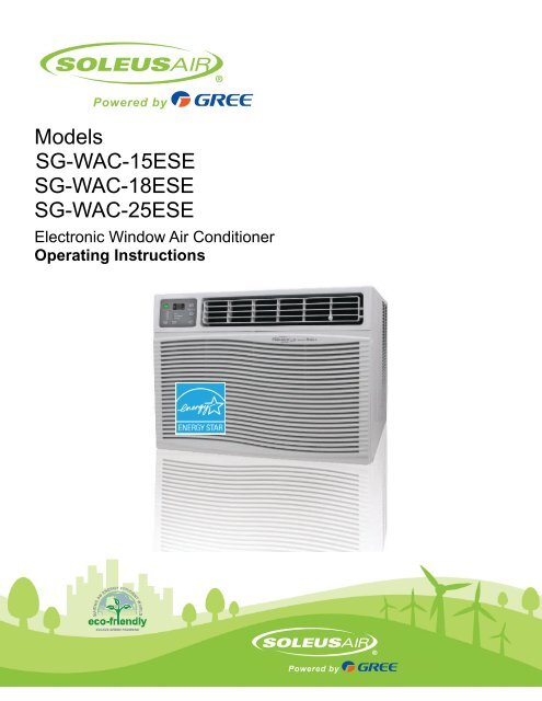
Models SG-WAC-15ESE SG-WAC-18ESE SG-WAC ... - Air & Water
Models SG-WAC-15ESE SG-WAC-18ESE SG-WAC ... - Air & Water
Models SG-WAC-15ESE SG-WAC-18ESE SG-WAC ... - Air & Water

You also want an ePaper? Increase the reach of your titles
YUMPU automatically turns print PDFs into web optimized ePapers that Google loves.
ELECTRICAL REQUIREMENTSThe electrical ratings for your air conditioner are listed on the model and serialnumber label located on the front left side of the unit (when facing the front).Specific electrical requirements are listed in the chart below. Follow therequirements below for the type of plug on the power supply cord.Wiring RequirementPower Supply CordElectrical Shock HazardPlug into a grounded 3 prong outlet.Do not remove the ground prong.Do not use an adapterDo not use an extension cord.Failure to follow these instructions can result in death,fire, or electrical shock208~230 Volt (197.2 min. - 253 max.)0-20 amps20-amp time-delay fuse orUse on single outlet circuit onlyRecommended Ground MethodFor your personal safety, this air conditioner must be grounded. This air conditioner is equipped with a 3 prong powersupply cord with a grounded plug. To minimize the possibility of electrical shock, the cord must be plugged into a 3 prongoutlet and grounded in accordance with all local codes and ordinances. If a 3 prong outlet is not available, it is the customer’sresponsibility to have a properly grounded 3 prong outlet installed by a qualified electrician.It is the customer’s responsibility:• To contact a qualified electrician• To assure that the electrical installation is adequateand in conformance with the National Electrical Code,ANSI/NFPA 70 - latest edition, and all local codes andordinances.Copies of the standards listed may be obtained from:National Fire Protection AssociationOne Batterymarch ParkQuincy, Massachusetts 02269LCDI Power Cord and PlugThis air conditioner is equipped with an LCDI (Leakage Current Detection and Interruption) power cord and plug asrequired by US National Electric Code 440.65. This cord consists of a length of shielded flexible cord with no terminationon the load side and a LCDI attachment plug on the line side.The LCDI power cord and plug will remove the supply source via electrical disconnect (circuit trip) if the nominal currentleakage between the cord shield and either load conductor exceeds a predetermined value. The cord will remain deenergizeduntil the devise has been manually reset. This is intended to reduce the risk of a fire in the power cord orcombustible materials nearby. The cord shields are not grounded and they must be considered a shock hazards ifexposed. The cord shield must not be connected to ground or to any exposed metal.The test and reset buttons on the LCDI Plug are used to check ifthe plug is functioning properly. To test the plug:1. Plug power cord into a wall outlet2. Press the TEST Button, the circuit should trip and cut allpower to the air conditioner3. Press the RESET button for useIf a test is performed and the indicator light remains ON, thecurrent leakage has been detected. Do not use the airconditioner or attempt to reset the LCDI Plug. Contact CustomerService for troubleshooting recommendations.3
PARTS LIST25ESE 25ESE15/<strong>18ESE</strong>WINDOW SASH SEALROUND HEADSAFETY LOCK AND3/4" ROUND-HEADSCREWWASHER HEADLOCKING SCREW(on 25ESE models)FOAM GASKETTOP ANGLEFRAMEASSEMBLY(LEFT)SIDE RETAINER37/8SEAL-BOTTOM RAIL TO UNIT1/2" LONGSCREWS ANDLOCKNUTSFRAMEASSEMBLY(RIGHT)LOCKNUT3/4" LONGFLAT HEADBOLTSILLANGLEBRACKETWINDOW SUPPORTBRACKETTOOLS NEEDEDLarge Flathead ScrewdriverTape MeasurerAdjustable Wrench or PliersPencilLevelSocket WrenchesPhillips Head ScrewdriverNon-Hardware Packing List• Window <strong>Air</strong> Conditioner• AAA Batteries (2) & Remote Control• Top Mounting Rail• Foam Top Mounting Rail Seal Strip• Accordion Panels (2)• Side Retainer (2)• Window Sash Seal• Foam Seal for Bottom Rail• Owner’s Manual4
SPECIFICATIONS• Noise level is measured at a distance of 3.28 ft away from the front of the unit in cooling mode.• Power consumption is measured when the fan runs at the highest speed setting.• These specifications are for reference only. For actual data, please refer to the rating label on the unit.Model<strong>SG</strong>-<strong>WAC</strong>-<strong>15ESE</strong>Power Supply (Ph/V/Hz)1/115/60HzDehumidifying Capacity (Pints/Day) 91.2Rated Cooling Capacity (BTU/h) 15,000Rated Heating Capacity (BTU/h) /Cooling Power Input (Watts) 1400Heating Power Input (Watts) /Rated Current Cooling (Amperage) 12Rated Current Heating (Amperage) /EER/C.O.P 10.8Noise Level db (A) Indoor/Outdoor 58/64CFM 480Design Pressure (PSIG) (H/L) /Dimensions (W” x H” x D”) 23.63 x 17.78 x 25.44Package Dimensions (W” x H” x D”) 28.28 x 19.97x 26.09Net/Gross Weight (Lbs) 110/129Refrigerant Charge (Oz) 28.22<strong>SG</strong>-<strong>WAC</strong>-<strong>18ESE</strong>1/230-208/60Hz129.618,000 /17,600/1680 /1650/8.1/8.8/10.759/64480/23.63 x 17.78 x 25.4428.28 x19.97 x 26.09110/12528.75<strong>SG</strong>-<strong>WAC</strong>-25ESE1/230-208/60Hz19224,500/24,000/2600 /2550/11.6/12.6/9.459/64400-490/26.54x 18.62 x26.3028.94x 20.1 x 31.69135/15240.565
INSTALLATION & ASSEMBLY INSTRUCTIONS - WINDOW MOUNTINGREMOVE CHASSIS1. Pull down the front panel and remove the filter (FIG. 1 below)2. Lift the front panel upwards to remove and place to the side.FIG. 1FIG. 23. Locate the four faceplate screws and remove. These screws will need to be re-installed prior to mounting the air conditioner(FIG. 2 above)4. After removing the screws, gently pull away the faceplate from the air conditioner cabinet (FIG. 3 & 4).FIG. 3 FIG. 45. Remove the shipping screws from the top of the unit (<strong>SG</strong>-<strong>WAC</strong>-25ESE only) and both sides of the cabinet if installed.6. Remove the two screws on the top of the chassis that hold the cabinet to the unit. Hold the cabinet while pulling onthe base of the chassis and remove the chassis from the cabinet (FIG. 5).7. Add two foam inserts to the holes on top of the cabinet where the shipping screws were located.8. There may be internal packing protection on the <strong>SG</strong>-<strong>WAC</strong>-25ESE. This packing material must be removed prior toinstallation (FIG. 6)FIG. 5FIG. 67
ASSEMBLY & INSTALLATION (CONT.)Install Support Brackets1. Hold each support bracket flush against the outside ofthe window sill. Tighten each bracket to the bottom ofthe cabinet as shown below. Mark the brackets at toplever of the window sill and then remove.Extend the Accordion Panels1. Carefully raise the window to expose the accordionpanel and panel frame. Loosen the locking screws sothe accordion panels slide easily.Locking ScrewFor 24KSill AngleBracketMarkLeftLocknutFlat Head Bolt1/2” Long Screwsand LocknutsRight3/4" Round-Head Screwfor 14/18K2. Extend each panel to completely fill the width of thewindow. Tighten the locking screws when the panelsare fully extended.3. Close window behind top angle.4. Set a locking screw on both sides of the curtain as shown.Install the Window Lock and Sash Seal1. Trim the sash seal to fit the width of the window. Insertthe sash seal into space between the upper and lowersashes.2. Assemble the sill angle brackets to the support bracketsat the marked position as shown above. Handtighten, but not all the way for any changes that mayneed to be made later during installation.3. Install the support brackets (with sill angle bracketsattached) to the bottom of the cabinet as shown below.4. Tighten all 6 bolts securely.2. Attach the right angle safety lock as shown below.1/2” longscrew andlocknuts9
ASSEMBLY & INSTALLATION (CONT.)Installing the Chassis into the Cabinet1. Team lift (two people) the air conditioner chassis andcarefully slide it into the cabinet. Let the front of the airconditioner hang out approximately 6”.2. DO NOT PUSH ON THE CONTROLS OR FINNEDCOILS.3. Be sure the chassis is firmly seated in the back of thecabinet.4. Insert all screws removed during window installationand reattach the front face plate, front panel, and theair filter. Use the REMOVE CHASSIS instructions andfigures 1-6 for reference.THRU-THE-WALL INSTALLATIONNOTE: Consult local building codes prior to installationand/or a qualified carpenter.Select the Wall LocationThis air conditioner has a slide-out chassis, so that it canbe installed through an outside wall as specified below:Model <strong>SG</strong>-<strong>WAC</strong>-25ESE <strong>SG</strong>-<strong>WAC</strong>-<strong>15ESE</strong> /<strong>SG</strong>-<strong>WAC</strong>-<strong>18ESE</strong>Max WallThickness12” 10”IMPORTANT: The side louvers must never be blocked.NOTE: All parts needed for Thru-The-Wall Installation areprovided, except a wood frame, shims, and 10 woodscrews (10-1” long minimum). Select a wall surface that:1. Does not support major structural loads such as theframe construction at ends of windows, and undertruss-bearing points, etc.2. Does not have plumbing or wiring inside.3. Is near existing electrical outlets, or where another outletcan or will be installed.4. Does not have objects blocking the air vents whichlimits cooling.5. Allows unblocked airflow from the rear and sides of theair conditioner.Prepare the Wall1. Prepare the wall in frame construction (including brickand stucco veneer). Working from inside the room, findthe wall stud that is nearest the center of the installationarea.FIG. 110
ASSEMBLY & INSTALLATION - THRU-THE-WALL (CONT.)Carefully measure and cut an opening with the followingdimensions depending on your model (FIG. 1 & 2).WIDTH “X” = inside model plus twice the thickness of theframing material used.HEIGHT “Y” = inside model height plus twice the thicknessof framing material used.Model <strong>SG</strong>-<strong>WAC</strong>-25ESE <strong>SG</strong>-<strong>WAC</strong>-<strong>15ESE</strong> /<strong>SG</strong>-<strong>WAC</strong>-<strong>18ESE</strong>NOTE: If wall thickness is 8-12” or more, add aluminumflashing over the bottom of the frame opening to assurewater is unable to enter the area between the inner andouter wall.Inside FrameHeightInside FrameWidth18 7/8” (47.9 cm) 18” (45.7 cm)26 3/4” (67.9 cm) 23 7/8” (60.6 cm)FIG. 2Prepare and Install the Cabinet1. Slide the chassis from the cabinet. Refer back to theREMOVE CHASSIS instructions and FIG. 1-6 in theWINDOW MOUNTING SECTION.2. Place the cabinet into the opening with the bottom railresting firmly on the bottom board of the wood frame.3. Position the cabinet so it is tilted properly for water removalas seen below.4. Build a wooden frame with the INSIDE dimensions ofyour model listed above (Measure twice). The framedepth should be the same as the wall thickness. Fill inextra space from the opening to the studs with woodspacers as shown below.5. Nail the spacers to the studs. They should be flush withthe dry wall.4. Secure the bottom rail to the wood frame with two large1” (2.5 cm) long wood screws as shown below.11
ASSEMBLY & INSTALLATION - THRU-THE-WALL (CONT.)MASONRY CONSTRUCTIONRefer to the SUPPORT BRACKET ASSEMBLY in theWINDOW MOUNTING section to assemble the supportbrackets. A wooden strip nailed to the outside wall shouldbe used in conjunction with the angled sill support brackets.SupportBracketWooden Strip5. Screw or nail the cabinet to the wooden frame usingshims if the frame is oversized, to eliminate possiblenoise. Remember to maintain proper slope for waterelimination.1. Cut or build a wall opening in the masonry wall similarto the frame construction (refer to the THRU-THE-WALL installation for a wall thickness greater than 81/2”)..2. Secure the cabinet in place using masonry nails, ormasonry anchor screws. Or, build a frame using theinstructions found in the THRU-THE-WALL installationsection.3. Make sure the masonry above the cabinet is supportedwell. Use the existing holes in the cabinet or additionaldrilled holes to fasten the cabinet at various positions.Make sure that the side louvers are clear of any obstructions.4. Install the exterior cabinet support brackets accordingto the SUPPORT BRACKET INSTALLATION instructionsin the THRU-THE-WALL installation section.Caulk or flash with aluminum if needed. This will providea tight seal around the top and sides of the cabinet.5. For a more aesthetically pleasing installation, applywood trim molding around the sides of the cabinet withoutobstructing the side louvers.6. Install the chassis into the cabinet by following thesteps described in the WINDOW MOUNTING section.OPTIONAL: Caulking and installation of the trim on theinterior wall may be done if desired. Caulk the openingsaround the top and sides of the cabinet and all sides of thewood sleeve to the opening.NOTE: See the WINDOW MOUNTING instructions for thebottom rail seal location.12
USING YOUR AIR CONDITIONERElectronic Control Panel & Remote ControlThis display always shows the roomtemperature except when settingthe Set temperature or the Timer.<strong>Air</strong> Conditioner Controls1-24Hr TimerTimerDecreaseMode ButtonDecreaseFan SpeedIncrease/DecreaseTemperatureRemote ControlNormal Operating SoundsWhen the light is on the unit is intemperature or timer set mode.Light Indicates theTimer is set.Timer IncreaseAuto Fan OnIncrease Fan SpeedPower Button• You may hear a pinging noise caused by waterhitting the condenser, on rainy days, or when thehumidity is high. This design feature helps removemoisture and improve efficiency.• You may hear the thermostat click when the compressorcycles on and off.• <strong>Water</strong> will collect in the base pan during rain ordays of high humidity. The water may overflowand drip from the outside part of the unit.• The fan may run even when the compressor isnot on.1. Power Button: Turns the air conditioner on andoff2. Digital Display: Displays the current room temperatureor the amount of time left on the timer.Shows the Set Temp when setting the temperature.Shows the Timer Set when setting the timer.The once the timer and/or temperature are set,the display will change to show the current roomtemperature. To see the set temperature again,simply press either of the Temp/Delay ▲/▼buttons.3. Temperature Set: Use these buttons on the controlpanel and remote to increase or decrease theSet Temperature (the desired room temperature)in cooling or energy saver mode. The SET lightwill light up when setting the temperature4. Timer Set: Use these buttons on the controlpanel and remote to set the Timer. Each press ofthe Timer (DELAY) buttons will increase or decreasethe timer. For timer instructions see #7.5. Fan Speed & Auto Fan: Use the fan speed buttonsto change the fan speed. Choose betweenlow, medium, high, and Auto. When using the remotecontrol, press the AUTO button to turn automode on and the FAN+ and FAN– buttons toselect low, medium, or high fan speed.6. Mode Button: Press the mode button to cyclethrough the various modes: Cooling, EnergySaver, and Fan only.7. Auto-on Timer: When the air conditioner is off, itcan be set to automatically turn on in 1-24 hoursat the previous set mode and fan setting. To setthe Auto-on Timer, press the DELAY button onthe unit or remote control. Each touch of the ▲/▼on the unit or the +/- buttons on the remote willchange the timer setting in 1 hour intervals. TheSET light will turn on while setting.Auto-off Timer: When the air conditioner is on, itcan be set to automatically turn off in 1-24 hours.To se the Auto-off Timer, press the DELAY buttonon the unit or remote control. Each ouch of the ▲/▼ on the unit or the +/- buttons on the remote willchange the timer setting in 1 hour intervals. TheSET light will turn on while setting.• To see the remaining time, press the DELAYButton. To change the timer setting use the▲/▼ on the unit or the +/- buttons on theremote.• To cancel the timer, press the DELAY buttonuntil the SET light turns off.13
USING YOUR AIR CONDITIONER (Cont.)• Freezing Conditions: This is a cooling only airconditioner. It is not designed for freezing outdoorconditions. It must not be used in freezing outdoorconditions.• Remote Control: To ensure proper operationwhen using the remote control, aim the remotedirectly at the signal receiver on the air conditioner.• The remote control has a signal range up to20 feet.• Make sure nothing is blocking the remote controlsignal from being received by the air conditioner.• Make sure the batteries are installed correctlyand still have power.• Cooling Mode: Use the COOL mode at Low, Medium,High, or Auto Fan speed when cooling isneeded. Use the temperature ▲/▼ buttons to setthe desired temperature between 64°F and 86°F.• Once the temperature is set, the compressorwill cycle on and off to keep the roomtemperature at the set temperature level. Thelower the set thermostat temperature, thecooler the room will become. The higher theset thermostat temperature, the warmer theroom will become.• For Normal Cooling - Set the Mode to Cooland the Fan to High or Med with thetermperature set in the middle.• For Maximum Cooling - Set the Mode to Cooland the Fan to High with a lower settemperature.• For Quieter & Nighttime Cooling - Set theMode to Cool and the Fan to Low with thetemperature set in the middle.NOTE: If the air conditioner is off and is thenturned on while set to a Cool setting or ifturned from a fan setting to a Cool setting, itmay take approximately 3 minutes for thecompressor to start and cooling to begin.• Energy Saver Mode - Controls the FanOn - The fan will cycle on and off with thecompressor. This results in winder variations of roomtemperature and humidity. Normally used with theroom is unoccupied. NOTE: The fan my continue torun for a short time after the compressor cycles off.Off - The fan runs all the time in fan or cooling mode.• Fan Only Mode: Use Fan Only mode at Low,Med, or High fan speed to provide air circulationand filtering without cooling. Since fan only settingdo not provide cooling, a Set temperature cannotbe entered. The room temperature will appear inthe display.NOTE: Auto Fan Speed cannot be used in FanOnly mode.• Loss of Power Protection: If power to the airconditioner is lost or interrupted, the air conditionerwill automatically re-start in the setting lastused prior to power loss. If the Timer was set toautomatically turn the air conditioner off or on, itwill resume countdown at the amount time leftprior to power loss. You may need to set a newtime if desired.• <strong>Air</strong> Direction: Use the lever near on the front airvents to adjust the direction of the airflow. Youcan direct the airflow left or right only. The lever islocated on the right side of the air vent.14
CARE AND CLEANINGClean your air conditioner to keep it looking newand to minimize dust build up.<strong>Air</strong> Filter CleaningThe air filter should be checked at least onceevery month to see if it needs cleaning. Trappedparticles and dust can build up in the filter andmay decrease airflow as well as cause thecooling coils to accumulate frost. To clean the airfilter:1. Remove the filter by pulling down on the indentsof the filter door on the front of the unit.(See FIG. 13)2. Wash the filter using liquid dish soap andwarm water. Rinse the filter thoroughly. Gentlyshake the filter to remove excess water.3. Let the filter dry completely before placing itinto the air conditioner.4. If you do not wish to wash the filter, you mayvacuum the filter to remove the dust andother particles.Cabinet CleaningTo clean the air conditioner cabinet:• Unplug the air conditioner to prevent shock ora fire hazard. The cabinet and front panel ofthe air conditioner may be dusted with an oilfreecloth or washed with a cloth dampened ina solution of warm water and mild liquid soap.Rinse thoroughly with a damp cloth and wipedry.• Never use harsh cleaners, wax or polish onthe cabinet front.• Be sure to wring excess water from the clothbefore wiping around the controls. Excesswater in or around the controls may causedamage to the air conditioner.Winter StorageTo store the air conditioner when it is not in usefor an extended period of time, remove it carefullyfrom the window according to the installationinstructions and cover it with plastic or place it inthe original box.FIG. 13Wear and TearTo minimize wear and tear on the air conditioner,always wait at least 3 minutes beforechanging modes. This will help prevent thecompressor from overheating and the circuitbreaker from tripping.15
TROUBLESHOOTINGPROBLEMThe <strong>Air</strong> Conditioner will not startThe <strong>Air</strong> Conditioner does not coolas it shouldThe <strong>Air</strong> Conditioner is freezing upThe Remote Control is not workingPOSSIBLE CAUSESThe air conditioner is unpluggedThe fuse is blown/circuit breaker istripped.Power FailureThe current interrupter device istripped.<strong>Air</strong>flow is restrictedThe temperature control may not beset correctly.The air filter is dirtyThe room may be too warmCold air is escapingThe Cooling Coils are frozenIce blocks the air flow and stops the airconditioner from cooling the roomThe batteries are inserted incorrectlyThe batteries may be deadSOLUTIONS• Make sure the air conditioner isplug is pushed completely into theoutlet• Check the house fuse/circuitbreaker box and replace the fuseor reset the breaker.• The unit will automatically re-startwhen power is restored.• There is a protective time delay(approx. 3 minutes) to preventtripping of the compressoroverload. For this reason, the unitmay not start normal cooling for 3minutes after it is turned back on.• Press the RESET button locatedon the power cord plug.• If the RESET button will not stayengaged, discontinue use of theair conditioner and contact aqualified service technician.• Make sure there are no curtains,blinds, or furniture blocking thefront of the air conditioner• Lower the set thermostat temperature• Clean the filter. See the Cleaningand Care Section of the manual.• Please allow time for the room tocool down after turning on the airconditioner.• Check for open furnace registersand cold air returns• See “<strong>Air</strong> Conditioner Freezing Up”below.• Set the MODE dial to HIGH FANor HIGH COOL and set the thermostatto a higher temperature• Check the position of the batteries.• Replace the batteries16
TROUBLESHOOTING (CONT.)PROBLEM<strong>Water</strong> is dripping outside<strong>Water</strong> is dripping inside the roomPOSSIBLE CAUSESHot and Humid weather.The air conditioner is not correctlytilted outside.SOLUTIONS• This is normal• For proper water drainage, makesure the air conditioner is slightlytilted downward from the front ofthe unit to the rear.<strong>Water</strong> collects in the base panMoisture removed from the air isdraining into the base pan.• This is normal for a short period inareas with low humidity and normalfor a longer period in areaswith high humidity.The <strong>Air</strong> Conditioner Display reads“EP”A Sensor has failed in the airconditioner• Contact customer service17
WARRANTYOne Year Limited WarrantySoleus International, Inc. warrants the accompanying Soleus <strong>Air</strong> Powered by Gree <strong>Air</strong> Conditioner to be free of defectsin material and workmanship for the applications specified in its operation instruction for a period of ONE (1) yearfrom the date of original retail purchase in the United States.If the unit exhibits a defect in normal use, Soleus International will, at its option, either repair or replace it, free ofcharge within a reasonable time after the unit is returned during the warranty period.As a condition to any warranty service obligation, the consumer must present this Warranty Certificate along with acopy of the original purchase invoice.THIS WARRANTY DOES NOT COVER:• Damage, accidental or otherwise, to the unit while in the possession of a consumer not caused by a defect inmaterial or workmanship.• Damage caused by consumer misuse, tampering, or failure to follow the care and special handling provisionsin the instructions.• Damage to the finish of the case, or other appearance parts caused by wear.• Damage caused by repairs or alterations of the unit by anyone other than those authorized by Soleus InternationalInc.• Freight and Insurance cost for the warranty service.• Filter and AccessoriesALL WARRANTIES, INCLUDING ANY IMPLIED WARRANTY OF MERCHANT ABILITY ARE LIMITED TOONE-YEAR DURATION OF THIS EXPRESS LIMITED WARRANTY. SOLEUS INTERNATIONAL INC.DISCLAIMS ANY LIABILITY FOR CONSEQUENTIAL OR INCIDENTAL DAMAGES AND IN NO EVENTSHALL SOLEUS INTERNATIONAL INC’S LIABILITY EXCEED THE RETAIL VALUE OF THE UNIT FORBREACH OF ANY WRITTEN OR IMPLIED WARRANTY WITH RESPECT TO THIS UNIT.This warranty covers only new products purchased from our authorized dealers or retailers. It does not cover used, salvaged,or refurbished products.As some states do not allow the limitation or exclusion of incidental or consequential damages, or do not allowlimitation on implied warranties, the above limitations and exclusions may not apply to you. This warranty gives youspecific legal rights, and you may also have other rights that vary from state to state.For Technical Support and Warranty ServicePlease Call (888) 876-5387Or Write To:Soleus International, Inc.20035 E. Walnut Dr. N.City of Industry, CA 91789www.soleusair.comwww.soleusgreen.com18
66129903756