ECEN 454 â Lab7: Design of 8-bit pipelined Adder with buffered H ...
ECEN 454 â Lab7: Design of 8-bit pipelined Adder with buffered H ...
ECEN 454 â Lab7: Design of 8-bit pipelined Adder with buffered H ...
- No tags were found...

Create successful ePaper yourself
Turn your PDF publications into a flip-book with our unique Google optimized e-Paper software.
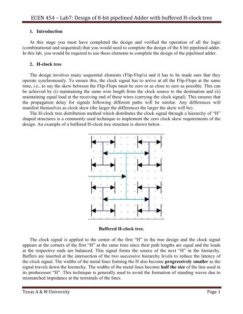
<strong>ECEN</strong> <strong>454</strong> – <strong>Lab7</strong>: <strong>Design</strong> <strong>of</strong> 8-<strong>bit</strong> <strong>pipelined</strong> <strong>Adder</strong> <strong>with</strong> <strong>buffered</strong> H-clock tree1. IntroductionAt this stage you must have completed the design and verified the operation <strong>of</strong> all the logic(combinational and sequential) that you would need to complete the design <strong>of</strong> the 8 <strong>bit</strong> <strong>pipelined</strong> adder.In this lab, you would be required to use these elements to complete the design <strong>of</strong> the <strong>pipelined</strong> adder.2. H-clock treeThe design involves many sequential elements (Flip-Flop's) and it has to be made sure that theyoperate synchronously. To ensure this, the clock signal has to arrive at all the Flip-Flops at the sametime, i.e., to say the skew between the Flip-Flops must be zero or as close to zero as possible. This canbe achieved by (i) maintaining the same wire length from the clock source to the destination and (ii)maintaining equal load at the receiving end <strong>of</strong> these wires (carrying the clock signal). This ensures thatthe propagation delay for signals following different paths will be similar. Any differences willmanifest themselves as clock skew (the larger the differences the larger the skew will be).The H-clock tree distribution method which distributes the clock signal through a hierarchy <strong>of</strong> “H”shaped structures is a commonly used technique to implement the zero clock skew requirements <strong>of</strong> thedesign. An example <strong>of</strong> a <strong>buffered</strong> H-clock tree structure is shown below.Buffered H-clock tree.The clock signal is applied to the center <strong>of</strong> the first “H” in the tree design and the clock signalappears at the corners <strong>of</strong> the first “H” at the same time since their path lengths are equal and the loadsat the respective ends are balanced. This signal forms the source <strong>of</strong> the next “H” in the hierarchy.Buffers are inserted at the intersection <strong>of</strong> the two successive hierarchy levels to reduce the latency <strong>of</strong>the clock signal. The widths <strong>of</strong> the metal lines forming the H also become progressively smaller as thesignal travels down the hierarchy. The widths <strong>of</strong> the metal lines become half the size <strong>of</strong> the line used inits predecessor “H”. This technique is generally used to avoid the formation <strong>of</strong> standing waves due tomismatched impedance at the terminals <strong>of</strong> the lines.Texas A & M University Page 1