elevator shaft mounting instructions - mod. âlaquilaâ - Donzelli Srl
elevator shaft mounting instructions - mod. âlaquilaâ - Donzelli Srl
elevator shaft mounting instructions - mod. âlaquilaâ - Donzelli Srl
- No tags were found...

Create successful ePaper yourself
Turn your PDF publications into a flip-book with our unique Google optimized e-Paper software.
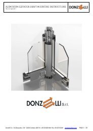
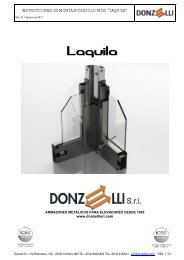
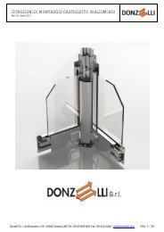
ELEVATOR SHAFT MOUNTING INSTRUCTIONS - MOD. “LAQUILA”Rel. 03 February 2011ELEVATOR SHAFTS SINCE 1965www.donzellisrl.com<strong>Donzelli</strong> S.r.l. Via Bizzozzero, 106 – 20032 Cormano (MI) Tel. +39 02 66301849 Fax +39 02 6152041 info@donzellisrl.com PAGE 1 / 29
ELEVATOR SHAFT MOUNTING INSTRUCTIONS - MOD. “LAQUILA”Rel. 03 February 2011CONGRATULATIONS!Like hundreds of other clients, you are now the owner of one of the best quality <strong>elevator</strong> steel <strong>shaft</strong>. The <strong>Donzelli</strong><strong>elevator</strong> steel <strong>shaft</strong> was designed to offer the best in terms of versatility, sturdiness and easiness of assembly.2-year warrantyEach <strong>Donzelli</strong> <strong>elevator</strong> steel <strong>shaft</strong> structure is guaranteed for 2 years. Should anyinconvenient happen, <strong>Donzelli</strong> will make the necessary repairs to restore proper functioningfree of charge for the whole duration of the warranty period.Tested and ApprovedEach structure produced by <strong>Donzelli</strong> is tested according to the methods prescribed byconstruction engineering and meets current safety standardsEN 81-1/2 “Safety rules for the construction and installation of lifts”NTC 2008 “Technical rules for constructions”Produced by <strong>Donzelli</strong> s.r.l.Excellent in terms of design and strength, each <strong>Donzelli</strong> <strong>elevator</strong> steel <strong>shaft</strong> is produced inour plant in Italy. We use only the best materials and comply with the highest productionstandards. Each structure is delivered in special packaging to ensure maximum protection.<strong>Donzelli</strong> and respect for the environmentRespect for the environment is one of the fundamental values of <strong>Donzelli</strong> s.r.l.All Materials used for packaging can be recycled.<strong>Donzelli</strong> S.r.l. Via Bizzozzero, 106 – 20032 Cormano (MI) Tel. +39 02 66301849 Fax +39 02 6152041 info@donzellisrl.com PAGE 2 / 29
ELEVATOR SHAFT MOUNTING INSTRUCTIONS - MOD. “LAQUILA”Rel. 03 February 2011Page4 Safety signs and symbols5 Verbal and body signals6 Operating temperatures, Mechanical characteristics, Maintenance7 Tools, screws8 Overall dimensions9 Uprights identification10 Crossbars11 Uprights junction12 Uprights Pit fixings13 Glass Holding Profile14 Enclosure panels sealing profile15 Enclosure panels16 Snap-on Glass Holding Profile (outer flush surface)17 Enclosure panels horizontal fixing plates18 Landing doors – top and bottom fixing plates19 Vertical fixing plates20 Header bracing crossbar21 Side bracing crossbars22 Fixings - Struts23 Fixings - External rings24 Landing door roof25 Roof - aluminum26 Roof – mild steel27 Landing doors side panels28 Elevator guides holding plates29 Packaging<strong>Donzelli</strong> S.r.l. Via Bizzozzero, 106 – 20032 Cormano (MI) Tel. +39 02 66301849 Fax +39 02 6152041 info@donzellisrl.com PAGE 3 / 29
ELEVATOR SHAFT MOUNTING INSTRUCTIONS - MOD. “LAQUILA”Rel. 03 February 2011Safety signs and symbolsThey make it mandatory to wear PPE and to behave with safety in mind.Fall-protection PPE ismandatoryGeneral warning (withsupplementary sign, ifapplicable)Mandatory safety glassesMandatory safetyhelmetMandatory breathingPPEMandatory safetyfootwearMandatory safety glovesMandatory overall bodyprotection<strong>Donzelli</strong> S.r.l. Via Bizzozzero, 106 – 20032 Cormano (MI) Tel. +39 02 66301849 Fax +39 02 6152041 info@donzellisrl.com PAGE 4 / 29
ELEVATOR SHAFT MOUNTING INSTRUCTIONS - MOD. “LAQUILA”Rel. 03 February 2011Verbal and hand signalsVerbal and hand communicationCommand: Attention: operationbeginningVerbal: STARTGesture: Both arms are extendedhorizontally with the palms facingforward.Command:Stop to interrupt or enda movementVerbal: STOPGesture: The right arm pointsupwards with the palm facingforwards.Command: End of operationVerbal: ENDGesture: Both hands are clasped atchest height.Command: RaiseVerbal: RAISEGesture: The right arm pointsupwards with the palm facingforward and slowly makes a circle.Command: LowerVerbal: LOWERGesture: The right arm pointsdownwards with the palm facing inwardsand slowly makes a circle.Command:Vertical distanceVerbal: MEASURE OF DISTANCEGesture: the hands indicate therelevant distanceCommand: Move forwardsVerbal: FORWARDGesture: Both arms are bent with thepalms facing upwards, and the forearmsmake slow movements towards the bodyCommand: Move backwardsVerbal: BACKWARDSGesture: Both arms are bent withthe palms facing downwards, andthe forearms make slow movementsaway from the body.Command: To the rightVerbal: RIGHTGesture: The right arm is extended moreor less horizontally with the palm facingdownwards and slowly makes smallmovements to the right.Command: To the leftVerbal: LEFTGesture: The left arm is extendedmore or less horizontally with thepalm facing downwards and slowlymakes small movements to the left.Command: Danger - Emergency stopVerbal: DANGERGesture: Both arms point upwards withthe palms facing forwards.Command:Horizontal distanceVerbal: MEASURE OF DISTANCEGesture: The hands indicate therelevant distanceQuick movementGesture: Conventional gestures used toindicate movements are faster.SlowmovementGesture: Conventional gesturesused to indicate movements areslower.<strong>Donzelli</strong> S.r.l. Via Bizzozzero, 106 – 20032 Cormano (MI) Tel. +39 02 66301849 Fax +39 02 6152041 info@donzellisrl.com PAGE 5 / 29
ELEVATOR SHAFT MOUNTING INSTRUCTIONS - MOD. “LAQUILA”Rel. 03 February 2011Operating TemperaturesThe <strong>Donzelli</strong> steel <strong>shaft</strong> is intended for indoor or outdoor applications with temperatures between –20°C and +60°CMechanical CharacteristicsThe <strong>Donzelli</strong> steel <strong>shaft</strong> consists of profiles obtained through working sheet metal type Fe 360B (classification accordingEN10025-90). All screws used are resistance class 8.0 or greater. Seals are made from EPDM (ethylene propylene diene), whichis highly resistant to chemicals and atmospheric agents.Powder coating is available upon request:MECHANICAL PROPERTIES WITH FILM THICKNESS OF 50/60 µm (IS0 2360)Adherence ISO 2409 G T øBuchholz Hardness ISO 2815 80 - 100Wolff Wilborg Pencil Hardness ASTM D 3363 H - 2HErichsen Drawing ISO 1520 8 mmCylindrical Chuck (4 mm) ISO 1519 Passes testDirect Impact ISO 6272 >2.5 NmIndirect impact ISO 6272 >2.5 NmCHEMICAL RESISTANCE AND SPECIFIC DATAResists aliphatic solvents, alcohol, diluted acids. Does not resist alkali, ketonic solvents and chlorinates.CORROSION AND OUTDOOR EXPOSURE TESTS:Tests conducted on small, 60mm-thick samples of aluminium sheet metal phosphochromed and painted with white polyesterTests conducted on small, 60mm-thick samples of aluminium sheet metal phosphochromed and painted with white polyester:Corrosion accelerated according to Kesternich (ISO 3231) - 2 I. of S02 x 24 cycles: No penetration of corrosion beyond 1mm from theedges of the cut.salt mist chamber resistance test (CASS-TEST) - ISO 9227 – duration 1000 hours: no penetration of corrosion beyond 1mm from theedges of the cut.humidistat ((ISO 6270) - 1000 hours: film unaltered, absence of blistering.Resistance to accelerated aging - UV-CON device 4-hour cyclesat 60°C, with lamps (313 UVB) + 4 hours of 100% humidity at 40°C:: after 200 hours, the loss of brightness is less than 50% of the initialvalue.Indicative data – Source: Pulverit S.p.A.Maintenance• Mechanical checksFor the annual inspection of the lift, check the tightening of screws and bolts.Check for water licks (panels and roof). If any, inspect the wear of the seals. If there are cuts or cracks, replace the seals.Check the fixings of the structure to the building.• CleaningTo clean the structure without damaging the surface finish, we suggest using water with some neutral detergent.. Acid, ammonia,or alcohol based detergents should be avoided as they are particularly aggressive and may damage the surface. Never clean thestructure with products that contain soda.For glass panels, use hot water with a spoonful of denatured alcohol or ammonia. Be careful not to touch the steel surfaces asthey may get corroded. If possible, do not clean glass surfaces when exposed to direct sunlight in that streaking may result.For painted sheet metal panels, clean them with water and neutral detergent. Acid, ammonia, or alcohol based detergents shouldbe avoided as they are particularly aggressive and may damage the surface. Never clean the structure with products that containsoda.<strong>Donzelli</strong> S.r.l. Via Bizzozzero, 106 – 20032 Cormano (MI) Tel. +39 02 66301849 Fax +39 02 6152041 info@donzellisrl.com PAGE 6 / 29
ELEVATOR SHAFT MOUNTING INSTRUCTIONS - MOD. “LAQUILA”Rel. 03 February 2011ToolsThe installation of <strong>Donzelli</strong> lift enclosures require the use of standard site tools, such as:Tape measure Ratchet wrench Power screwdriverScrewdrivers Plumb-line Hammer drillOpen-ended wrenchesHammerList of HardwareFollowing is a full list of the hardware SUPPLIED in the packaging, along with their PARTS numbers:V120189Hex head bolt M12x30V170012V120158Hex head bolt M10x25V190510Hex nut M12 Grower washer Ø10.2V190512V190856Grower washer Ø12.2 Washer with seal Ø 6,3x19V190012Flat washer Ø13x24V160752Self-threading TS Phillips-head screw Ø3.9x16V160820Self-threading TC Phillips-head screw Ø4.2x19V110115Threaded rod M12 x 3000DZ95060Guide fastening plate M12 (Cookie)DZ95239Door fastening plate M10 (Cookie)V150130Expansion anchor M12X110DZ95219Self-adhesive glass sealDZ95270Self-adhesive glass seal<strong>Donzelli</strong> S.r.l. Via Bizzozzero, 106 – 20032 Cormano (MI) Tel. +39 02 66301849 Fax +39 02 6152041 info@donzellisrl.com PAGE 7 / 29
ELEVATOR SHAFT MOUNTING INSTRUCTIONS - MOD. “LAQUILA”Rel. 03 February 2011OVERALL DIMENSIONS• <strong>Donzelli</strong> steel <strong>shaft</strong> is available in 3 different<strong>mod</strong>els:• PRES-STD: with press formed uprights dim.100 x 100mm• PRES-CURV: with rounded uprights dim. 100x 100mm• PRES-SLIM: with slim uprights (entranceside) dim. 50 x 110mm• Above shown <strong>mod</strong>els can be combined toobtain hybrid solutions to better suit yourneedsLEGEND:• SW = Shaft width• SD = Shatf depthPART LIST<strong>Donzelli</strong> S.r.l. Via Bizzozzero, 106 – 20032 Cormano (MI) Tel. +39 02 66301849 Fax +39 02 6152041 info@donzellisrl.com PAGE 8 / 29
ELEVATOR SHAFT MOUNTING INSTRUCTIONS - MOD. “LAQUILA”Rel. 03 February 2011UPRIGHTS IDENTIFICATION• NOTE: Uprights are supplied in lengths up to3mt. The length of each set of uprights mayvary according to the specifications and thestructural design.• Top and bottom uprights: These are easilyrecognizable as they have a plate welded toone end (Picture “A”). To distinguish betweenthe pit and top uprights, check the position ofthe holes for assembling the crossbars (1).These positions are shown on the projectdrawing.12• Intermediate uprights: These can be identifiedby a series of holes located at the base of theupright (2). The number of holes correspondsto the assembly position (ex. 1 hole = firstlevel above the uprights in the pit).• Figure “C” shows an example of a projectdrawing, provided for illustrative purposesonly. Project drawings are specific for eachstructure.Picture “A”Picture “B”• NOTE: The uprights are built in such amanner that they can be positioned on anyside of the structure.PART LISTPicture “C”<strong>Donzelli</strong> S.r.l. Via Bizzozzero, 106 – 20032 Cormano (MI) Tel. +39 02 66301849 Fax +39 02 6152041 info@donzellisrl.com PAGE 9 / 29
ELEVATOR SHAFT MOUNTING INSTRUCTIONS - MOD. “LAQUILA”Rel. 03 February 2011CROSSBARS• NOTE: Materials required to complete thisstep is supplied in the box code “DZ9F217 –Crossbar and Glass Holder Hardware". Thenumber of kits supplied varies according tothe height of the structure (1 kit = 3 mt inheight).• Identify and separate the front crossbars fromthe side crossbars. For this step, please referto the project drawing to distinguish thedifferent lengths.• Fasten the crossbars to the uprights using thehardware indicated. The crossbars aresupplied with a threaded insert that hasalready been riveted in order to facilitate theassembly of the parts.• The crossbars above and below the landingdoors must always be assembled where the13 x 60 slots are located. These slots allowthe height of the crossbars to be adjusted +/-25 mm (compensation for floor level).PART LIST1 M12 HEXAGONAL INSERT2 Ø12.2 FLAT WASHER3 M12X30 HEX HEAD SCREW1 2 3<strong>Donzelli</strong> S.r.l. Via Bizzozzero, 106 – 20032 Cormano (MI) Tel. +39 02 66301849 Fax +39 02 6152041 info@donzellisrl.com PAGE 10 / 29
ELEVATOR SHAFT MOUNTING INSTRUCTIONS - MOD. “LAQUILA”Rel. 03 February 2011Picture “A”UPRIGHTS JUNCTION• NOTE: Materials required to complete thisstep is supplied in the box “DZ9F214 –Upright Joining Kit". The number of kitssupplied varies based on the number of joints(1 kit = 1 joint).• After positioning the bottom uprights, positionthe first set of intermediate uprights as shownon Figure “A”.• Position the external (1) and internal (2) jointsleeves inside the uprights. The externalsleeve is supplied with an M12 nut welded onthe back..• Fasten the sleeves to the uprights using the 8external bolts.• Fasten the sleeves together using the twocentre bolts.213456PART LIST1 EXTERNAL SLEEVE2 INTERNAL SLEEVE3 M12 HEX NUT4 Ø12.2 FLAT WASHER5 Ø12.2 GROWER WASHER6 M12X30 HEX HEAD SCREW<strong>Donzelli</strong> S.r.l. Via Bizzozzero, 106 – 20032 Cormano (MI) Tel. +39 02 66301849 Fax +39 02 6152041 info@donzellisrl.com PAGE 11 / 29
ELEVATOR SHAFT MOUNTING INSTRUCTIONS - MOD. “LAQUILA”Rel. 03 February 2011UPRIGHTS PIT FASTENING• NOTE: Materials required to perform this stepare supplied in blister pack code “DZ9F2201– M12 anchor bolts Kit”• After plumbing the structure, make a Ø12 holeat least 100 mm deep as shown on the figure.• Fasten the uprights to the pit slab using theanchor bolts supplied.1PART LIST1 M12 ANCHOR BOLT<strong>Donzelli</strong> S.r.l. Via Bizzozzero, 106 – 20032 Cormano (MI) Tel. +39 02 66301849 Fax +39 02 6152041 info@donzellisrl.com PAGE 12 / 29
ELEVATOR SHAFT MOUNTING INSTRUCTIONS - MOD. “LAQUILA”Rel. 03 February 2011GLASS HOLDING PROFILE• NOTE: Materials required for this step issupplied in box code “DZ9F217 - Crossbarand Glass Holder Hardware Kit”• The glass holding profiles are supplied indifferent lengths based on the size of thevarious mirrors. Please refer to the projectdrawing to identify which one is needed.1• Position the glass holding profile as shown onFigure “B”. Make sure to align the edgesindicated with the arrows.• Fasten the profile using the countersunk selfthreadingscrews.2• IMPORTANT: Use at least 2 screws to fasteneach profile. Use only the countersunk holes.Fig. “A”21Fig. “B”PART LIST1 GLASS HOLDING PROFILE2 COUNTERSUNK SELF-THREADING SCREWSAINNER FLUSH SURFACEABBOUTER FLUSH SURFACEFig. “C”<strong>Donzelli</strong> S.r.l. Via Bizzozzero, 106 – 20032 Cormano (MI) Tel. +39 02 66301849 Fax +39 02 6152041 info@donzellisrl.com PAGE 13 / 29
ELEVATOR SHAFT MOUNTING INSTRUCTIONS - MOD. “LAQUILA”Rel. 03 February 2011ENCLOSURE PANELS SEALINGRUBBER PROFILE• In order to guarantee better seal, the <strong>Donzelli</strong>LAQUILA steel <strong>shaft</strong> is supplied with a selfadhesiverubber sealing profile. This sealeliminates the need for silicon the panels.• After carefully cleaning the edges of theprofiles shown with the arrows, remove theprotective film and position the seal on theframe as shown on the figure. The adhesiveallows the seal to remain in place evenwithout the panel.• Press on edge shown by the arrows againstthe frame to guarantee that the adhesivebonds.• Make a 45° cut in the seal at the corners asshown on Picture “B”. This joint must be madecorrectly in order to guarantee proper sealingof the panel.• IMPORTANT: The seal is supplied in rolls ofmax. 100 m. The amount provided iscalculated based on the specific needs ofeach structure. It is important that you performany cuts with a minimum waste.1Fig. “A”• IMPORTANT: DO NOT STRETCH THERUBBER GASKET DURING THEMOUNTINGPART LIST1 SELF-ADHESIVE SEALFig. “B”ABINNER FLUSH SURFACE VERSIONOUTER FLUSH SURFACE VERSIONAB<strong>Donzelli</strong> S.r.l. Via Bizzozzero, 106 – 20032 Cormano (MI) Tel. +39 02 66301849 Fax +39 02 6152041 info@donzellisrl.com PAGE 14 / 29
ELEVATOR SHAFT MOUNTING INSTRUCTIONS - MOD. “LAQUILA”Rel. 03 February 2011ENCLOSURE PANELS• Before positioning the panels, make sure thatthe seal is correctly positioned along theentire perimeter of the mirror.• Position the panel as shown on the figure.Make sure that the bottom and two sides restonto the seal.1• IMPORTANT: Inner flush surface version:Always start from the top when positioning thepanels. Make certain that at least the upperhorizontal panel strip has been mountedbefore moving on to the next panel below.Outer flush surface version: Position thepanels and secure them in place by the meanof the specific snap-on glass holding profilesas described in the following chapter• CAUTION: Special personal protectionequipment is required when handling glass(gloves, protective glasses). If using suctioncups, clean the contact surface carefully andmake certain that the load bearing weight ofthe tool is greater than the weight of the glass.Fig. “A”2PART LIST1 GLASS / ALUMINUM PANEL2 MILD STEEL PANELFig. “B”<strong>Donzelli</strong> S.r.l. Via Bizzozzero, 106 – 20032 Cormano (MI) Tel. +39 02 66301849 Fax +39 02 6152041 info@donzellisrl.com PAGE 15 / 29
ELEVATOR SHAFT MOUNTING INSTRUCTIONS - MOD. “LAQUILA”Rel. 03 February 2011SNAP-ON GLASS HOLDINGPROFILE (outer flush surface only)2• After saving identified the profiles of theproper length, set them in place as shown infigure “A”• IMPORTANT: Snap-on profiles (1) aresupplied 25mm longer than the respectiveglass holding profile (2)• NOTE: snap-on profiles have been designedto accom<strong>mod</strong>ate either 8mm or 10mmlaminated glass• For 8mm laminated glass orientate the profileas shown in picture “B1”1• For 10mm laminated glass orientate theprofile as shown in picture “B2”• IMPORTANT: To make sure the snap-onprofiles can be mounted easily, extrusion’scoupling tolerances have been kept quitelarge, which may result in an unstableconnection between the profiles. The<strong>mounting</strong> of the vertical fixing plate will lockthe snap-on profile in place.Fig. “A”1 2PART LIST1 SNAP-ON GLASS HOLDING PROFILE2 GLASS HOLDING PROFILEFig. “B”<strong>Donzelli</strong> S.r.l. Via Bizzozzero, 106 – 20032 Cormano (MI) Tel. +39 02 66301849 Fax +39 02 6152041 info@donzellisrl.com PAGE 16 / 29
ELEVATOR SHAFT MOUNTING INSTRUCTIONS - MOD. “LAQUILA”Rel. 03 February 2011ENCLOSURE PANELSHORIZONTAL FIXING PLATES• NOTE: Materials required for this step issupplied in box code “DZ9F217 - Crossbarand Glass Holder Hardware Kit”• Identify and separate the front plates from theside plates. For this step, please refer to theproject drawing to distinguish the differentlengths.• Press the panel against the structure andposition the plate on the crossbar. Fasten it inplace using self-threading screws and theassistance of a power screwdriver.• For the guide side, use the special plates withopenings as shown on picture “B”.• IMPORTANT: Make certain the upper andlower edges of the panel strip press againstthe panel itself. The pressure of the panelagainst the seal ensures proper seal. If not,replace the strip.3• IMPORTANT: Shape of the horizontal fixingplate vary depending on the structure’spaneling (inner or outer flush surface) asshown in picture “B”Fig. “A”1PART LIST1 HORIZONTAL PANEL PLATE2FIXING PLATE (INNER FLUSH SURFACEVERSION)FIXING PLATE (OUTER FLUSH SURFACE3VERSION)4 ROUND HEAD SELF-THREADING SCREWS2Fig. “B”43<strong>Donzelli</strong> S.r.l. Via Bizzozzero, 106 – 20032 Cormano (MI) Tel. +39 02 66301849 Fax +39 02 6152041 info@donzellisrl.com PAGE 17 / 29
ELEVATOR SHAFT MOUNTING INSTRUCTIONS - MOD. “LAQUILA”Rel. 03 February 2011LANDING DOORS TOP ANDBOTTOM FIXING PLATES• NOTE: Materials required for this step issupplied in box code “DZ9F217 - Crossbarand Glass Holder Hardware Kit”• In order to assemble the enclosure panelsafter positioning the landing doors, the aboveand below door strips are supplied in piecesfor automatic doors and in whole strips forhinged doors.3• For automatic doors: After positioning thepanel, fasten the plates (1) in the spacebetween one threshold fastening bracket andthe other as shown on Picture “A” (bracketsnot SUPPLIED).Picture “A”1• IMPORTANT: Make certain the panel isfastened with at least 3 strips.• For Hinged doors: Position the plates (2) asshown on Figure “B”.• Acting in the vertical slots, position the strip sothat the gap with the floor door threshold isclosed (smooth, continuous wall).• IMPORTANT: Position the strip in order toguarantee at least 12 mm overlap on thepanel.• IMPORTANT: In order to position the panel,make certain that the bottom part of thebracket does not protrude beyond thelower/upper edge of the crossbar.PART LIST1 FIXING PLATE (AUTOMATIC DOOR)2 FIXING PLATE (HINGED DOOR)3 ROUND HEAD SELF-THREADING SCREWS3Picture “B”2<strong>Donzelli</strong> S.r.l. Via Bizzozzero, 106 – 20032 Cormano (MI) Tel. +39 02 66301849 Fax +39 02 6152041 info@donzellisrl.com PAGE 18 / 29
ELEVATOR SHAFT MOUNTING INSTRUCTIONS - MOD. “LAQUILA”Rel. 03 February 2011VERTICAL FIXING PLATE1• NOTE: The vertical fixing plates are suppliedin lengths up to 3 m.• Pit bottom plate: The length is equal to that ofthe pit bottom uprights – 5 mm.• Headroom plate: The length is equal to that ofthe header uprights – 100 mm.• Intermediate plates: The lengths are equal tothose of the uprights on which they must bepositioned.• Position the vertical plates on the uprights.Fasten them using the special self-threadingscrews.• NOTE: Push button cables, locks cables, etc.can be run through the space inside theuprights.• IMPORTANT: Make certain the upper andlower edges of the panel strip press againstthe panel itself. The pressure of the panelagainst the seal ensures proper seal. If not,replace the strip.12PART LIST1 VERTICAL PLATES2 ROUND HEAD SELF-THREADING SCREWS<strong>Donzelli</strong> S.r.l. Via Bizzozzero, 106 – 20032 Cormano (MI) Tel. +39 02 66301849 Fax +39 02 6152041 info@donzellisrl.com PAGE 19 / 29
ELEVATOR SHAFT MOUNTING INSTRUCTIONS - MOD. “LAQUILA”Rel. 03 February 2011HEADER BRACINGCROSS-BARS• NOTE: Materials required to perform this stepare supplied in box “DZ9F222 - HeaderCross-Bar Kit”• Position the eye screws (1) as shown in thepictures• Measure the diagonal distance between theeye screws to determine the length of thethreaded rods required and cut them to size.• Slide the threaded rod through the hole of theeye screw as indicated in Picture “A” andfasten it using the required bolts.• Adjust the tension of the threaded rods andthen lock them tightening the nut.Picture “A”Picture “B”• NOTE: Header cross-bar is supplied only ifrequired (refer to the technical calculationreport for details) or upon request.231• NOTE: If headroom service crossbar ispresent, mount the crossbars upside down(with eye screw facing upward)• IMPORTANT: Using a header bracingcrossbar reduces by approx 30mm theheadroom324PART LIST1 M10 EYE SCREW2 M10 HEX NUT3 Ø10,2 FLAT WASHER4 M12 X 3000 THREADED RODPicture “C”<strong>Donzelli</strong> S.r.l. Via Bizzozzero, 106 – 20032 Cormano (MI) Tel. +39 02 66301849 Fax +39 02 6152041 info@donzellisrl.com PAGE 20 / 29
ELEVATOR SHAFT MOUNTING INSTRUCTIONS - MOD. “LAQUILA”Rel. 03 February 2011SIDE BRACING CROSS-BARS• NOTE: Materials required to perform this stepare supplied in box “DZ9F225 - Side Cross-Bar Mounting Kit”• Identify <strong>mounting</strong> positions of crossbars(which side of the <strong>shaft</strong>) referring to theproject drawing (see page 8)• Install the eye screws (1) as shown on picture“B”Picture “A”• Measure the distance between the eyescrews (diagonally) to determine the length ofthe rods, then cut them to lenght23• Mount the threaded rods (4) as shown onpicture “B”, adjust the tension using the nutshown by the arrow. Once the tension hasbeen adjusted, lock them in place bytightening the nut• NOTE: Side cross-bar are supplied only ifnecessary (refer to the technical calculationreport for details) or upon request.1234Picture “B”• IMPORTANT: Side crossbars cause areduction of <strong>shaft</strong> space of approx. 45mmPART LIST1 M10 EYE SCREW2 Ø10,2 FLAT WASHER3 M10 HEX NUT4 M12 X 3000 THREADED RODPicture “C”<strong>Donzelli</strong> S.r.l. Via Bizzozzero, 106 – 20032 Cormano (MI) Tel. +39 02 66301849 Fax +39 02 6152041 info@donzellisrl.com PAGE 21 / 29
ELEVATOR SHAFT MOUNTING INSTRUCTIONS - MOD. “LAQUILA”Rel. 03 February 20111FIXINGS - STRUTS• NOTE: Materials required to perform this stepare supplied in box “DZ9FXXX – Crossbarsfixings Kit”32• Drill a Ø 15mm hole on the crossbar asshown on picture “A”• Drill a Ø 15 x 100mm hole onto the wallcoaxial to the one shown above• Cut the pipe (2) to the desired lenght54• Depending on the type of the wall, apply theresin (1) as shown on the charts at the bottomof the page• Mount the threaded rod (3) tightening the nut(5) locking the pipe between the wall and thesteel structurePicture “A”CODE L (mm) RANGE (mm)XXX 200 da 0 a 200XXX 500 200 0 a 500XXX 1000 da 500 a 1000XXX 1500 da 1000 a 1500IMPORTANT: Unless otherwise stated, at least 3uprights must be connected to a structuralelement (e.g. building’s wall), at a distance notgreater than 3,5mt among them. Pit andheadroom of the structure must also be securelyfastened onto the buildingELENCO COMPONENTI1 CHEMICAL ANCHOR M12 (NOT SUPPLIED)2 Ø 30mm STEEL PIPE3 THREADED ROD M124 Ø12,2 FLAT WASHER5 M12 HEX NUTANCHORING ONTO STONE WALLS,CONCRETE AND BRICK WALLSANCHORING ONTO CAVITY BRICK WALLS<strong>Donzelli</strong> S.r.l. Via Bizzozzero, 106 – 20032 Cormano (MI) Tel. +39 02 66301849 Fax +39 02 6152041 info@donzellisrl.com PAGE 22 / 29
ELEVATOR SHAFT MOUNTING INSTRUCTIONS - MOD. “LAQUILA”Rel. 03 February 2011FIXINGS – EXTERNAL RINGS1• NOTE: to determine quantity and position offixing rings please refer to the TechnicalCalculation Report• NOTE: Materials required to perform this stepare supplied in box “DZ9F205 – Fixing ringsMounting Kit”• Join the two sections of the ring (1) by themean of the connecting pipe (3)1• Drill a Ø 12mm hole (2) by the fixing platesand secure the ring to the structure• Insert the fixing plate (4) compensating thedistance to the wall (adjustment range-30/+ 30 mm), then tight the fastening boltsADJUSTMENT RANGE5324• IMPORTANT: Unless otherwise stated, atleast 3 uprights must be connected to astructural element (e.g. building’s wall), at adistance not greater than 3,5mt among them.Pit and headroom of the structure must alsobe securely fastened onto the buildingPART LIST12Refer to kit DZ9F205 PART LIST345 M12 CHEMICAL ANCHOR (NOT SUPPLIED)ANCHORING ONTO STONE WALLS,CONCRETE AND BRICK WALLSANCHORING ONTO CAVITY BRICK WALLS<strong>Donzelli</strong> S.r.l. Via Bizzozzero, 106 – 20032 Cormano (MI) Tel. +39 02 66301849 Fax +39 02 6152041 info@donzellisrl.com PAGE 23 / 29
ELEVATOR SHAFT MOUNTING INSTRUCTIONS - MOD. “LAQUILA”Rel. 03 February 2011LANDING DOOR ROOF• NOTE: Materials required to perform this stepare supplied in blister pack code “ DZ9F223 -Landing Door Roof Kit”• Place the frame of the landing door roof at thedesired height and mark the position of theholes onto the uprights• Drill n°4 Ø13mm holes keeping a 80mmcenter-to-center distance as shown on picture“B” (see the arrows)Fig. “A”• Secure the frame to the steel structure by themean of the specific screws as shown onpicture “C”• Operating from the top side, place the glassinside the frame and seal it with transparentsilicon• Connect the water draining pipe if present• NOTE: Landing Door Roof provided uponrequest onlyFig. “B”1 234PART LIST1 M12 HEX NUT2 Ø12,2 GROWER WASHER3 Ø12,2 FLAT WASHER4 M12X30 HEX HEAD SCREWFig. “C”<strong>Donzelli</strong> S.r.l. Via Bizzozzero, 106 – 20032 Cormano (MI) Tel. +39 02 66301849 Fax +39 02 6152041 info@donzellisrl.com PAGE 24 / 29
ELEVATOR SHAFT MOUNTING INSTRUCTIONS - MOD. “LAQUILA”Rel. 03 February 2011ALUMINUM ROOF• NOTE: Materials required to perform this stepare supplied in blister pack code “ DZ9F207 -Roof <strong>mounting</strong> hardware Kit ”• Place the roof as shown on picture “A”• Screw the roof in place. Inclination of the roofcan be obtained by adjusting the protrusion ofthe threaded rod from the top of the upright(picture “B”)Picture “A”• NOTE: When the steel structure is adjacent tothe building, roof will be provided withoutprotrusion on such side123Picture “B”PART LIST1 Ø12,2 FLAT WASHER2 M12 HEX NUT3 THREADED ROD M12X200Fig. “B”<strong>Donzelli</strong> S.r.l. Via Bizzozzero, 106 – 20032 Cormano (MI) Tel. +39 02 66301849 Fax +39 02 6152041 info@donzellisrl.com PAGE 25 / 29
ELEVATOR SHAFT MOUNTING INSTRUCTIONS - MOD. “LAQUILA”Rel. 03 February 2011MILD STEEL ROOF• NOTE: Materials required to perform this stepare supplied in blister pack code “ DZ9F314 -mild steel roof <strong>mounting</strong> hardware Kit ”245• Referring to the main drawing, determine thedirection of the slope and then mount the front(1) and rear supports (2) as shown in picture“A”• Install the crossbars (3) by the mean of theproper M10 screws and bolts3• Set the top cover sheet (4) and secure it inplace by the mean of the specific self tappingscrews and licking-proof washers• Repeat the above mentioned step to set theother top cover sheet (5)1Fig. “A”ABPART LIST1 FRONT SUPPORTING PLATE2 REAR SUPPORTING PLATE3 CROSSBARS4 TOP COVER SHEET5 TOP COVER SHEETFig. “B”ABFLAT (SLOPED) VERSIONDOUBLE RIDGE VERSION<strong>Donzelli</strong> S.r.l. Via Bizzozzero, 106 – 20032 Cormano (MI) Tel. +39 02 66301849 Fax +39 02 6152041 info@donzellisrl.com PAGE 26 / 29
ELEVATOR SHAFT MOUNTING INSTRUCTIONS - MOD. “LAQUILA”Rel. 03 February 2011LANDING DOOR SIDE PANELS1• NOTE: Materials required to perform this stepare supplied in blister pack code “DZ9F224 –Landing door side panels Kit”Picture “A”423Picture “B”• NOTE: The side panels are supplied withholes to make installation easier. Only selfthreadingscrews are required for all fasteningoperations on to the structure.• Position the top panel (if present) inside thelintel as shown on Picture “A” and fasten it tothe structure as shown on Picture “C”.• Position the side panels as shown on picture“A” and fasten them to the structure as shownon picture “B”.• NOTE: The size and finish of the panels varybased on the design specifications. To definethe position for assembly, please refer to theproject drawing.• IMPORTANT: The side panels are justaesthetical components, not load bearingelements. Therefore we recommend fasteningthe floor door frame to the upper and lowercrossbars.PART LIST1 TOP PANEL2 LEFT PANEL3 RIGHT PANEL4 COUNTERSUNK SELF-THREADING SCREWSPicture “C”<strong>Donzelli</strong> S.r.l. Via Bizzozzero, 106 – 20032 Cormano (MI) Tel. +39 02 66301849 Fax +39 02 6152041 info@donzellisrl.com PAGE 27 / 29
ELEVATOR SHAFT MOUNTING INSTRUCTIONS - MOD. “LAQUILA”Rel. 03 February 2011ELEVATOR GUIDESHOLDING PLATES• NOTA: Materials required to perform this stepare supplied in box code “ DZ9F226 - ElevatorGuides Holding Plates Hardware Kit”• Place n°4 plates (1) inside the crossbar asshown on picture ”A”• Fasten the <strong>elevator</strong> guides holding brackets tothe plates by the means of the M12 screwssupplied1• Tight the screws making sure that the platesrotate as shown on picture “B”• IMPORTANT: maximum torque 50N/mPicture “A”Picture “B”PART LIST1 M12 HOLDING PLATES2 Ø12,2 FLAT WASHER3 M12X30 HEX HEAD SCREWPicture “C”12 3<strong>Donzelli</strong> S.r.l. Via Bizzozzero, 106 – 20032 Cormano (MI) Tel. +39 02 66301849 Fax +39 02 6152041 info@donzellisrl.com PAGE 28 / 29
ELEVATOR SHAFT MOUNTING INSTRUCTIONS - MOD. “LAQUILA”Rel. 03 February 2011PACKAGING• NOTE: All <strong>Donzelli</strong> packaging in made out of100% recyclable materials. The woodencases are treated according to theinternational standard for phytosanitarymeasures, F.A.O. ISPM 15.Picture “A”• Cardboard packaging (Picture “A”):Water resistant (not waterproof) doublecorrugatedcardboard packaging.Max stacking: 2 unitsSquared OSB headerSealed using Nylon strappingCan be handled with pallet jacks.• Crate packaging (Picture “B”):Water resistant (not waterproof) firpackaging,Max stacking: 3 unitsNailed closedCan be handled with pallet jacks.Picture “B”• Crate packaging (Picture “C”):Water resistant (not waterproof) firpackaging,Cannot be stackedNailed closedCan be handled with pallet jacks.Please dispose waste properly.LOVE YOURSELF – PROTECT THEENVIRONMENTPART LISTPicture “C”<strong>Donzelli</strong> S.r.l. Via Bizzozzero, 106 – 20032 Cormano (MI) Tel. +39 02 66301849 Fax +39 02 6152041 info@donzellisrl.com PAGE 29 / 29