Gladiator Conductivity Quickstart - Hawk Measurement
Gladiator Conductivity Quickstart - Hawk Measurement
Gladiator Conductivity Quickstart - Hawk Measurement
- No tags were found...

Create successful ePaper yourself
Turn your PDF publications into a flip-book with our unique Google optimized e-Paper software.
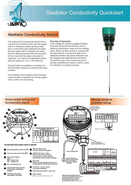
<strong>Gladiator</strong> <strong>Conductivity</strong> <strong>Quickstart</strong><strong>Gladiator</strong> <strong>Conductivity</strong> SwitchThe probe of the <strong>Conductivity</strong> Switch formsone part of an electric circuit, with the vesselwall or a reference probe making anotherpart. A conductive liquid between the probeand the vessel wall (or between the probeand the reference probe) links the two partsof the circuit and the output will switch inresponse. The output has adjustable hysteresisand delays for ‘on’ or ‘off’ switching.A test function is available to remotely confirmthe probe integrity by switching the relaycontacts.Principle of OperationA low voltage AC signal is applied betweenthe probe electrode and the tank wall (orreference electrode in case of a non-metallictank). When the liquid comes in contact withthe electrode tip, a conductive path is establishedbetween the sense electrode andthe metallic tank wall/reference electrode.Current flow due to the conductive path issensed, amplified and used to switch a relayfor indication or control purposes.The <strong>Gladiator</strong> Smart Switch Series includescommunications capability for remote adjustment,control and monitoring.Smart probe wiring andfunctionality layoutRemote probe toamplifier wiring9Remove Plug-Interminal block foreasier wiring.634128SENSITIVITYsignalHI FSH CAL TESTONON1 2 1 2LO FSL OFF OFF1 2 3 4 5 6 7 8 9 10DELAY152SMART PROBE REMOVABLETERMINAL BLOCKRELAY COMMS DC-IN AC-IN1 2 3 4 5 6 7 8 9 10GLADIATOR REMOTE PROBE TERMINAL LAYOUTTRANSDUCER1. 2. 3. 4. 5. 6. 7. 8. 9. 10.WHITEBLUETerminals 1, 2, 3, 4, 9, 10 not used.REDBLACK107111. NC2. COM3. NO4. Test5. A6. B+ -N7.8.9.10. L1Functionality Description (bold is default)RS 48512-30VDC 80-265 VACHole for securing ofoptional identification tag1234Mounting Calibration switch CAL/OFFTest input function select TEST/OFFRelay action selectionswitchFSH - FailSafe HighFSL - FailSafe LowHI / LO sensitivity switch789RED LED: Relay statusON when relay coil is energisedGREEN LED: Power / StatusBlinks to indicate the functioningis correct and no media is detected.Continuously ON when media is detected.BLUE LED:Blinking indicates calibration function is on.Continuously ON indicates failed calibration.M4 grounding screwGround the housing tovessel, if vessel is metallic.Ground the housing toplant ground, if vessel isnon-metallic.GLADIATOR REMOTE AMPLIFIER TERMINAL LAYOUTNOT USEDRELAY 1 RELAY 2(FAIL SAFE)Test inNCCOMNONCCOMNOCURRENT SENSOR COMMS DC-IN AC-IN5Delay Potentiometer (0-20 sec)(Default 0 sec. at minimumposition)1011AC Ground - must be used forAC powered installationsRemovable terminal block - plug in typeIs+ –REDBLACKBLUEWHITENOT USEDBA– +NL124 VDC 80-265 VAC6Sensitivity PotentiometerDefault 50% = 12 o’clock12 Signal indicatorNot used in <strong>Gladiator</strong> <strong>Conductivity</strong> productsCable type between Amplifier and Probe4 conductor shielded twisted pair instrument cable.Conductor size dependent on cable length.BELDEN 3084A, DEKORON or equivalent.Max: BELDEN 3084A = 500m (1640 ft)Max: DEKORON IED183AA002 = 350m (1150 ft)
Setup ProcedureSmart Probe Version1. Mount the unit in its actual position.Make sure that external ground wire is connectedbetween the outside ground screw on the <strong>Gladiator</strong>housing and the roof/wall/side of the silo/tank/vessel/chute.(For non metallic tanks make sure thatexternal ground wire is connected between thesame outside ground screw on the housing and thegeneral plant ground potential).2. Check where the actual level is relative to theprobe.Make sure that the liquid is not touching the probeor probes.3. Turn the power on.The green LED will either stay on for 2 seconds thenbegin flashing or stay on permanently to indicateoperation.4. Select the required relay contact action.The Relay can switch ‘ON’ or ‘OFF’ as the productapproaches the probe and switch ‘ON’ or ‘OFF’ in responseto an instrument failure. Set the relay actionselection switch position (FSL or FSH) depending onyour requirements.5. Cancel influence of mounting.Do not proceed with this step unless the liquid is nottouching the probe or probes.Switch the Mounting Calibration switch to ‘CAL’(ON) position. The Blue LED will blink to indicatethat mounting calibration is now in progress.Wait for at least 10 sec. then switch the mountingcalibration switch to ‘OFF’ position. The blue LEDshould turn off after a short time. The blue LED willstay on if there was a calibration error. If this is thecase please check that the probe is not touchingthe product or the mounting, then try the calibrationagain. If mounting calibration was successful theblue LED should be off and the Green LED shouldblink every 2 sec.Unit is now able to cancel influence of mounting andprobe history has been cleared.6. Select the sensitivity.There are two adjustments controlling the sensitivityof the switch point:6.1. The ‘HI/LO’ sensitivity switch is used toset your unit depending on the conductivity of theproduct to be measured. This switch sets the rangeof adjustment possible with the sensitivity potentiometer.If the material to be detected has a lower conductivitythan 1750µS/cm (4400µS/inch) - set the switch to‘HI’ (ON) - default.If material to be detected has a higher conductivitythan 1750µS/cm (4400µS/inch)- you may set the switch to ‘LO’. If you are not awareof your material’s conductivity – set the switch to ‘HI’(ON) - default.6.2 The sensitivity potentiometer.Set the potentiometer according to your requirements.A 12 o’clock setting (50%) - default, willcover the majority of instances - for the remaininginstances, turning the potentiometer clockwise willincrease sensitivity. Increasing sensitivity maybenecessary if the liquid is not detected when touchingthe probe.7. Select the time delaySet the required delay using the Delay potentiometer.(Default is 0 sec. at minimum position) Turnthe potentiometer clockwise if any delay is required.Maximum rotation is ¾ of a revolution. Max delay is20 sec. The selected delay will be used for both anON delay and an OFF delay.*8. Test function (used to check for malfunctionof unit from remote position, PLC, SCADA etc)Select the desired Test function by switching the‘Test’ switch (Default = ‘OFF’).‘TEST’ (ON) Position: Test function is selected. Testterminal (terminal number 4 of Smart probe) is usedas an input to the unit. The test function allows youto check the functionality of the unit. Applying aground wire to the Test terminal will change the stateof the relay. It will hold this state until the ground isremoved, then it will change back to the standardrunning mode. If the unit was in a Fail mode then therelay will not change status.‘OFF’ (Default) Position: Fail safe output function isselected. Test terminal (terminal number 4 of Smartprobe) will function as an open drain drive. This canbe used to drive a relay or an active low PLCinput to detect a Fail condition. In normal operationmode the Test terminal will output ZeroVolts (Short to GND). In Fail or unpoweredmode the Test terminal will be open circuit.See the manual for further information.WiringMountingRelay FunctionsLevel SwitchContact ActionRelay - for SmartProbe VersionRelay 1 - forRemote VersionState 1Single Switch PointRISING LEVELDual Switch PointsORRISING LEVELFailSafe LowFSL1 2 3NCCOMRelay ActionNOFailSafe HighFSH (default)1 2 3NCCOMNORelay StatusSmart Probeterminal numbersRemote Amplifierterminal functionlabelsLED StatusIncorrectPossible conductivebuild-upIf necessary, mount aprotection plate toprevent direct impact.CorrectCorrectIncorrectIncorrectPossibleproductbuild-upState 21 2 31 2 3NC COM NOCorrect30-45ºCONTACT LEVELCONTACT LEVELFALLING LEVELCorrectState 11 2 3NC COM NO1 2 3NC COM NOFALLING LEVELPOWER FAILURE1 2 3NC COM NO1 2 3NC COM NOHousing can be rotatedwithin 200º after themounting thread istightened, to allow cableentries to face downwardsor allow optimal cableclearance.CorrectFailSafe Switch Contact ActionRelay 2 - Remote version only.For Smart Probes the Test terminalcan act as a solid state output with asimilar function.POWER FAILUREORINTERNAL FAILURESYSTEM OPERATINGNORMALLYNC COM NO NC COM NONCCOM NONC COM NOIncorrectCorrect (non-preferredlow level mounting)Contact<strong>Hawk</strong> <strong>Measurement</strong> Systems AustraliaPhone: +61 3 9873 4750info@hawk.com.au<strong>Hawk</strong> <strong>Measurement</strong> USPhone: +1 888 429 5538info@hawkmeasure.comFor global representatives:www.hawkmeasure.comPart number: Doc-<strong>Conductivity</strong>-Quick