Download File - Hawk Measurement Systems!
Download File - Hawk Measurement Systems!
Download File - Hawk Measurement Systems!

You also want an ePaper? Increase the reach of your titles
YUMPU automatically turns print PDFs into web optimized ePapers that Google loves.
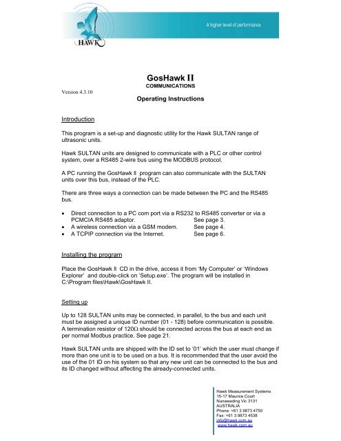
Setting Communications ParametersClick ‘View’, click ‘Options’. The ‘Properties’ screen comes up.If using a Direct connection to a PC com port via a RS232 to RS485 converteror via a PCMCIA RS485 adaptor157253461234567Set this field to the ID of the unit you wish to talk to.(02 in this example)Select ‘Comms’ for Direct ConnectionEnter the number of the Port that your RS485 comms is on.This is the rate at which parameters are read (and/or written).Leave ‘Speed’ at 19200 bps for SULTAN.This is the time that the program will wait to get a valid response fromthe SULTAN, for each query. 10mS is suitable for direct connection.Tick this box if the firmware in the SULTAN transducer is earlier thanversion 1.36. This can be confirmed from the ‘Info Screen’. See page 9Connect the SULTAN ultrasonic unit to the PC via a RS232 to RS485 converter orPCMCIA RS485 adaptor. Three connections are required, A, B & GND. This can bedone via a user’s system bus provided that no other unit on the bus has the ID of 01.The user’s PLC or control system must be disconnected. See Page 21.See page 20 for typical PCMCIA wiring.Page | 3
Click the ‘Connect’ button ( 1on page 2) to establish communication. The buttonicon changes to a hung-up telephone and is now used to disable communicationClick the ‘Setup’ button (Go to page 63on page 2) to bring up the ‘Quick Start Menu’ screen.If using the wireless connection via GSM modem…12346567812345678Set this field to the ID of the unit you wish to talk to.Select ‘Modem’ for GSM wireless connection.Enter the number of the Port that your computer’s modem is on.This is the rate at which parameters are read (and/or written).Enter the phone number of the modem you want to call. Press TAB.Leave ‘Speed’ at 19200 bps for SULTANThis is the time that the program will wait to get a valid response fromthe SULTAN, for each query. A longer time (Typically 1500mS) isrequired for modem transmission.Tick this box if the firmware in the SULTAN transducer is earlier thanversion 1.36. This can be confirmed from the ‘Info Screen’. See page 9Page | 4
Block diagram of a GSM connectionPC runningGos<strong>Hawk</strong> IIRS232ModemPSTN(Any distance)GSMNetworkRS485 BusOther units on busSultan withGSMModulefittedGSMClick the ‘Connect’ button ( 1 on page 2) The button icon changes to ahung-up telephone and is now used to disable communication.The ‘Dial Number’ box comes up as shown below.Click ‘OK’The ‘Status’ box indicates call progress.When the connection is established, click the ‘Setup’ button ( on page 2)3to bring up the ‘Quick Start Menu’ screen. Go to page 6Page | 5
• If using a TCP-IP connection via the Internet…This option is not available yet.Changing the Device ID of a SULTAN unitWhen communication has been established with a SULTAN, its Device ID canbe changed if required. To do this, follow these steps…1 Bring up the properties screen by clicking on ‘View’ and then ‘Options’.Double-click here to bring up the‘Device ID Information’ screen forthe new ID. ( ‘02’ in this case)2 Click the down arrow of the ID box, select the desired new ID from thelist, if it is not in the list it can be added at the bottomPage | 6
3 Double-click on the ID bar as shown above, the ‘Device ID Information’screen comes up.1234 Click ‘Write ID’ 1 a box comes up asking for the current ID number.5 Enter the current ID number. (01 in this example) Click ‘OK’26 Click ‘Close’3Page | 7
Reading & Writing ParametersClicking the Read/Write Parameters (Setup) button (up the ‘Quick Start Menu’ screen as shown below.3on page 2) brings1Parameters that were read successfully and were legitimate will be displayedon a green background. A red panel will be displayed if a parameter cannotbe accessed or is outside normal limits.Changing parametersClick on any parameter field to alter it. The field will turn gray. The data maynow be altered. Leaving the field by ‘enter’ or ‘tab’ will cause the data to bewritten to the device and read back. If the new value was successfully writtenand read back that field will turn green. A value outside normal limits will notbe accepted and the field will turn red.To initiate a new read of all parameters (refresh),click the ‘Read All Parameters’ button 1Clicking the Down Arrow of the ‘Setup’ button gives the option of displaying…• Info• Quick Start• Tx Setup• Tracking• FactoryPage | 8
The ‘Info’ screenTransducer Setup MenuPage | 9
Tracking MenuFactory MenuPage | 10
DiagnosticsClicking on the ‘Diagnostic’ button (similar to this below.4on page 2) brings up a screen112473589610 11 12 13The top section1is a graph of the loop current output over time.Positioning the cursor anywhere on the trace will display the current value atthat point, in the top right corner2while the mouse button is held down.The bottom section 3 is a display of the echos received, their amplitudeand their distance.The ‘step’ in the horizontal white line4represents the time ‘window’ inwhich the unit is looking for a valid echo.The horizontal yellow line5represents the threshold. (0.4v in this case)The horizontal distance scale can be expanded or contracted with the ‘Scale’adjustment.6The total length can be 1m, 10m, 20m, 40m, or 60mClicking anywhere, the tip of an echo for example, will display the voltage atthat point, in the top right corner.7Page | 11
The following data are displayed on the right side of the screen:8Dist:E-Dist:Size:Gain%:Recov:Noise%:Temp:Confirm:Hold:WinUp:WinDw:The distance (in metres) from the transducer face to theproduct being measured. This corresponds to the greendisplayed echo.Estimated Distance. Used during start-up to get anapproximate distance before the advanced processingproduces the final value.The minimum amplitude for an echo to be accepted whenin the recover mode.The percentage of gain that is being used for thismeasurement.The gain percentage increase applied to recover from aloss of signal.The noise level expressed as a percentage of gain.The current temperature (in degrees Centigrade)measured at the transducerThe number of consecutive, consistent echos receivedbefore being confirmed as valid.The number of transmit-and-measure cycles performed,when no echo is detected, before the unit goes intoRecover mode.The distance per pulse that the window will moveforwards to go to another echo when the unit is in therecover modeThe distance per pulse that the window will movebackwards to go to another echo when the unit is in therecover mode.NoteIn the Recover mode the window will double in width after the Hold No countsdown to zero. If no echo is confirmed in this larger window the recover modewill continue until the window covers the position of the echo. The output willthen move to the new echo position at a rate dictated by the damping number.Page | 12
Echos that are ‘mapped out’ are displayed in red. This information is only readfrom the SULTAN once, so if a change is made to the mapping the display willnot be updated until the refresh button 9 is clicked.The three windows along the bottom 10 11 12configured to display a number of variables…can each beWindow 10• Threshold• Blankingcan beWindow 11 can be• Recover• Recover Increment• Dist Step 3• WindowWindow 12 can be• Slope• Gain Step 1• Dist Step 1• Gain Step 2See the <strong>Hawk</strong> SULTAN Manualfor explanation of these termsClick the ‘Log’ button 13 to activate the data-logging function, a boxcomes up in which you specify the location and filename for the data file.A text file will be created and each line contains the following data…Date,Time,Device ID,Distance,E_Dist,Size,Gain,Recover,Noise,Temp, Confirm,Hold,Win Start,Win End,EchoNo1,Start Dist1,Peak Dist1,Size1,Gain1,EndDist1,EchoNo2,Start Dist2,Peak Dist2,Size2,Gain2,EndDist2,EchoNo3,Start Dist3,Peak Dist3,Size3,Gain3,EndDist3,EchoNo4,Start Dist4,Peak Dist4,Size4,Gain4,EndDist4,EchoNo5,Start Dist5,Peak Dist5,Size5,Gain5,EndDist5,EchoNo6,Start Dist6,Peak Dist6,Size6,Gain6,EndDist6,EchoNo7,Start Dist7,Peak Dist7,Size7,Gain7,EndDist7,EchoNo8,Start Dist8,Peak Dist8,Size8,Gain8,EndDist8,EchoNo9,Start Dist9,Peak Dist9,Size9,Gain9,EndDist9,EchoNo10,Start Dist10,Peak Dist10,Size10,Gain10,EndDist10Page | 13
Tank viewClicking the ‘Tank View’ button ( 5 on page 2) allows the data frommultiple units to be displayed, nine units per screen, as shown below.In this example, Device ID records have been created for seven units (01 -07) but only one unit (device ID = 02) is connected.If more than nine device ID records exist, buttons for the next and subsequentscreens will be displayed herePage | 14
Updating FirmwareThe SULTAN firmware can be overwritten (flashed) to load updated or specialcustomized versions.The amplifier and transducer programs are loaded separately andindependently.RequirementsSoftware to load – this will be supplied as a .pga file for the amplifier and/or a.pgt file for the transducer.Adaptor board and cable – only required for programming the transducer ofan integral unit.ProcedureLoad the program file(s) into a suitable folder in the computer such asc:\program files\hawk\goshawk\software.It is wise to move any old or obsolete .pga and .pgt files that mayhave been left from a previous programming session, into a separatefolder, such as ...\software\oldProgramming the Transmitter (Amplifier)Click the down arrow of the ‘Flash’ button. ( 6 on page 2)Select ‘Transmitter’ (amplifier)A box comes up asking“Do you want to flash the transmitter?”Click ‘Yes’A ‘Look in’ box requests the location of the file to be loaded.Navigate to the folder where you stored the program file(s).c:\program files\hawk\goshawk\software for this example.Select the appropriate .pga file.Click ‘Open’.The Status bar says “Flashing Device 001” and indicates progress.When finished a box comes up saying “Flashing was successful”Click ‘OK’Page | 15
Programming the TransducerRemote TransducerLeave the transducer power wires (Red & Black) connected to theamplifier unit but disconnect the signal wires (White & Blue) andconnect them, instead, to the RS485 line from the computer.White = A, Blue = B.Also connect ground between Sultan and computer.Integral TransducerUnplug the cable from the transducer to the terminal board (5-pinconnector) and plug it into the ‘TO TX’ socket on the adaptor board.Connect the ‘TO AMP’ socket on the adaptor board to the (now vacant)transducer socket on the terminal board (HAW-AWI TM) using a 5-waycable.TERMINAL BOARDHAW-AWI TMTO AMPAdaptor boardHAWK TXAMPABCOMPUTERRS485TO TXGNDTRANSDUCERConnect the A, B, GND terminals on the adaptor board to the RS485line from the computer.Click the down arrow of the ‘Flash’ button ( 6 on page 2).Select ‘Transducer’A box comes up asking “Do you want to flash the transducer?”Click ‘Yes’Page | 16
A ‘Look in’ box requests the location of the file to be loaded.Navigate to the folder where you stored the program file(s).c:\program files\hawk\goshawk\software for this example.Select the appropriate .pgt file.Click ‘Open’.The Status bar says “Flashing Device 001” and indicates progress.When finished a box comes up saying “Flashing was successful”Click ‘OK’Disconnect power from the Sultan.Disconnect the adaptor board (if used) and re-connect the transducer.Page | 17
TroubleshootingUnable to communicate with a HAWK device?Check the communication parameters, correct Com port selected?Note that it is possible for windows to re-assign a logical com portnumber to a different hardware port. Port operation can be confirmedby connecting a CRO between Ground (Pin 5) and Data Out (Pin 3).(for a 9-pin connector) Set the sensitivity to 5V/div and the timebase to2mS/div. If the port is working, the output will be at approx –12v withdata pules going to +12V when the ‘Connect to Parameters’ button isclicked, as shown below.0VRS232 DATA OUTPUT FROM PCPage | 18
Check that the RS232 to RS485 converter is working by observing theRS485 output when data is sent by the PC. Data on the bus should bebetween 10V and 2V p-p, measured between the bus wires. Use aCRO with isolated ‘ground’ such as the Fluke 123 Scopemeter.Interrogationfrom controllerResponse from SULTANSCREEN FROM SCOPEMETER CONNECTED ACROSS THE BUSEnsure that the correct model (SULTAN or GLAD) has been entered inthe DEVICE ID INFORMATION screen. See page 7.Check that the Device ID selected in the program matches that of theactual device.Page | 19
RS485 Biasing2200Ω+24v680Ω 5.6v+24vARS232RS-232To150Ω RS485 busRS-485ConverterB120ΩGND680ΩGNDThe above network can be used if noise is causing problems with RS485transmission. It biases the bus into the idle state when no device istransmitting, that is ‘A’ is held about 500mV more positive than ‘B’ when alldrivers are in the high-impedance state.This whole network replaces the 120Ω termination resistor at the converterend of the bus.D9 Male5 oo 9oooooo 61 oABGNDConnections for the Quatech RS485 PCMCIA cardPage | 20
MODBUS Communication with multiple Sultan unitsA 120 ohm termination resistor must beconnected across the bus at both ends.Avoid stubs if possible.Maximum number of units on bus is 128. 120120ΩPC RunningtheGOSHAWK IIprogramRS232RS232 485 +TO 485 -RS485 +VCONVERTER GNDPOWERSUPPLY 24V +Allow for 100mA -average per unitHAWKSULTANID = 02HAWKSULTANID = 03- - - -HAWKSULTANID = nPage | 21