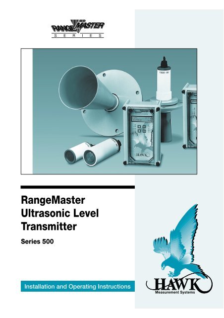
RangeMaster Ultrasonic Level Transmitter - Hawk Measurement ...
RangeMaster Ultrasonic Level Transmitter - Hawk Measurement ...
RangeMaster Ultrasonic Level Transmitter - Hawk Measurement ...
- No tags were found...

You also want an ePaper? Increase the reach of your titles
YUMPU automatically turns print PDFs into web optimized ePapers that Google loves.
<strong>Ultrasonic</strong> Series 500INTRODUCTIONCONTENTSPROPRIETARY NOTICEThe information contained in this publication isderived in part from proprietary and patent data.This information has been prepared for the expresspurpose of assisting operating and maintenancepersonnel in the efficient use of the instrumentdescribed herein.Publication of this information does not conveyany rights to use or reproduce it, or to use for anypurpose other than in connection with theinstallation, operation and maintenance of theequipment described herein.Copyright 1995Printed by Graphic Zone, AustraliaAll Rights Reserved.YEAR 2000 COMPLIANCEThe equipment and/or software described in thismanual is Year 2000 Compliant, and as such is inno way affected by the roll over from December31, 1999 to January 1, 2000.WARNINGThis instrument contains electronic componentsthat are susceptible to damage by static electricity.Proper *handling procedures must be observedduring the removal, installation, or handling orinternal circuit boards or devices.* Handling Procedure:1. Power to unit must be removed.2. Personnel must be grounded, via wrist strap orother safe, suitable means, before any printedcircuit board or other internal device is installed,removed or adjusted.3. Printed circuit boards must be transported ina conductive bag or other conductive container.Boards must not be removed from protectiveenclosure until the immediate time ofinstallation. Removed boards must be placedimmediately in a protective container fortransport, storage, or return to factory.• Comments:This instrument is not unique in its content of ESD(electrostatic discharge) sensitive components.Most modern electronic designs containcomponents that utilize metal oxide technology(NMOS, CMOS, etc.) Experience has proven thateven small amounts of static electricity can damageor destroy these devices. Damaged components,even though they appear to function properly,exhibit early failure.PRINCIPLE OF OPERATION 2SPECIFICATIONS 5INSTALLATION- Transducer- Amplifier7MOUNTING DIMENSIONS 10WIRING GUIDE 13DATA INPUT 18QUICK START 19QUICKSTART ~ Flow Chart - Entering Setup 23QUICKSTART ~ Flow Chart - Menus 24QUICKSTART ~ Flow Chart - Set Transducer 25QUICKSTART ~ Flow Chart - Digitising 25QUICKSTART ~ Flow Chart - Setup 26SCALING YOUR VESSEL 27SOFTWARE TREE OVERVIEW 31SET UP ~ Description 32SET UP ~ Description - Relays 33SET UP ~ Flow Chart 35TEST ~ Description 37TEST ~ Flow Chart 38RESTARTING THE RANGEMASTER 39RESETTING THE RANGEMASTER 39ADJUSTING THE LIQUID CRYSTALDISPLAY VIEWING ANGLE 39DIAGNOSTIC DISPLAY 39ERROR CODES 40TROUBLESHOOTING 41CONNECTING AN OSCILLOSCOPE 42CONNECTING HAWKLOG 43WARRANTY 49PART NUMBERING 491
<strong>Ultrasonic</strong> Series 500PRINCIPLE of OPERATIONThe Range Master ultrasonic levelmeasurement system operates bytransmitting an ultrasonic signal from thetransducer towards the product beingmonitored. The reflected signal or echo isreceived by the transducer and processed bythe amplifier. The time between transmissionof the ultrasonic signal and reception of theecho is measured, and using the speed ofsound through air, the distance from thetransducer to the product being monitoredis calculated. The <strong>Hawk</strong> Range Master systemuses sophisticated software to locate andtrack the correct echo without being affectedby echos from fixed objects or changes in theproduct surface. When the product level orsurface conditions change, the system adoptspre-selected signal tracking parameters. Inthe event of a total loss of signal, the systemadopts pre selected signal recovery routinesto relocate the correct product level. Thesystem employs automatic gain control tocompensate for changes in echo amplitude,due to changes in environmental conditions.The system has continuous current, voltageand relay outputs. These outputs can beprogrammed for failsafe conditions in theevent of a loss of signal or system malfunction.The factory settings are based on years ofexperience in acoustically difficultapplications. This typically means that thesystem can be installed and made operationalin a minimum of time.DIGITISINGDigitising is a software routine that createsan acoustic map of the vessel beingmonitored. The map is used to storeinformation about the system transmit pulseand the amplitude and location of all echoeswithin the mapped distance. The Mappeddata is used during signal processing, andprovides a high level of discrimination toremove the effects unwanted echoes.Refer figures 1, 2, and 3. Unwanted echoescan be caused by imperfections in thetransducer mounting and by features withinthe vessel i.e. ladders, struts, support beams.Digitising, along with transducer mountingand location are crucial steps in setting upyour <strong>RangeMaster</strong> and if done correctly, willenhance system performance.RECIEVED SIGNALValid EchoTransmit pulseFigure 1Unwanted EchoDIGITISED DATATransmit pulseFigure 2PROCESSED SIGNALValid EchoFigure 32
<strong>Ultrasonic</strong> Series 500SPECIFICATIONSAMPLIFIERRANGERMHA125RMA100RMA 20RMA 100 - 125m (375 ft)0 - 100m (240 ft)0 - 30m (90 ft)0 - 15m (45 ft)POWER CONSUMPTIONMax 18VA on ac powerMax 630mA/24VdcLEVEL ALARM RELAYS6 x S.P.D.T. 10 amp/280Vac*ACCURACY0.2% of Full RangeRESOLUTION0.1% of RangeDISPLAY16 Character Alphanumeric LCD(Single Channel)32 Character Alphanumeric LCD (DualChannel)Adjustable Viewing AngleMEMORYAll parameters stored in non volatileEEPROM. Data retained for 10 yearswithout power.OPERATING TEMPERATURE-20° to 60°C (-4° to 140°F)ANALOG OUTPUT CURRENTNominal range (adjustable)ØmA - 20mA4mA - 20mAVoltage <strong>Level</strong> 7 - 32VdcOver Voltage ProtectedReverse Polarity ProtectedMaximum Load: 750 Ohms @ 24VdcConnection - Current Drive or ModulatingOptically Isolated to 3000V ContinuousSUPPLY VOLTAGE110Vac 50/60Hz +/- 15%240Vac 50/60Hz +/- 15%24Vdc +/- 15%FAILSAFE RELAY1 x S.P.D.T 10Amp/280Vac per channel**Relay contacts must be protected byfuses with appropriate characteristics.FUSE PROTECTION250mA - 110Vac/240Vac630mA - 24VdcENCLOSUREIP67 (NEMA 4X)1(UL Approved)Width Height Depth186mm x 302mm x 175mm- Polyester F.R.P.TRANSDUCEROPERATING TEMPERATURE-20º to 80ºC (-40º to 176ºF) Teflon Face-20º to
<strong>Ultrasonic</strong> Series 500SPECIFICATIONS cont'dTRANSDUCER cont'dFACE MATERIALPolyolefinTitaniumTeflonGylonFLANGE MOUNTINGAnsi, JIS, DIN. Refer page 11.NIPPLE MOUNTING1.00 N.P.T. BSP.Other sizes available on request.EXTERNAL TEMPERATURE SENSORHOUSING MATERIALPolypropyleneCABLINGTRANSDUCERR-146 Tri-axial Cable orBelden 9222 Tri-axial Cable orRG-62U Coaxial Cable(must be run in grounded metal conduit).Maximum Cable Length is 185 metres(600feet) for all types of cable.Note: Use of wrong cable will seriously affectthe systems performance.TEMPERATURE SENSORType 9462 Belden or similar.Maximum Cable Length is 50 metresRESPONSE TIME< 8 minutesOPERATING TEMPERATURE-20º to 110ºC (-4º to 230ºF)MOUNTING1" NPTSOUND VELOCITIESSound Velocities for Gases at 0ºCMetres/Second Feet/SecondDry air 331 1086Ammonia 415 1362Argon 308 1010Carbon Dioxide 259 850Carbon Monoxide 338 1109Chlorine 206 676Dueterium 890 2920Ethane (10ºC) 308 1010Ethylene 317 1040Helium 965 3166Hydrogen 1284 4213Hydrogen Bromide 200 656Hydrogen Chloride 206 676Hydrogen Iodide 157 515Hydrogen Sulfide 289 948Gases cont'd Metres/Second Feet/SecondIlluminating (Coal Gas) 453 1486Methane 430 1411Neon 435 1427Nitric Oxide (10ºC) 324 1063Nitrogen 334 1096Nitrous Oxide 263 863Oxygen 316 1037Sulphur Dioxide 213 699Sound Velocities for Vapours at 0ºCAcetone 230 755Benzene 202 663Carbon Tetrachloride 145 476Chloroform 171 561Ethanol 269 883Ethyl Ether 206 6766
<strong>Ultrasonic</strong> Series 500INSTALLATION GUIDEAMPLIFIERSelect a suitable mounting position that isnot in direct sunlight. If necessary, utilize asunshade. Refer figure 13, page 10. Observethe minimum and maximum temperaturelimits (-20°C/-4°F to 60°C/140°F) Do not mountnear sources of high E.M.F. such as highcurrent cables, motor starters, or S.C.R.variable speed drives. Avoid mounting in highvibration areas such as handrails and rotatingplant. Use rubber absorption mounts ifmounting in light vibration areas. Removethe P.C.B. assembly before drilling cable andconduit entry holes.TRANSDUCERSelecting a suitable position to mount thetransducer on the vessel is the single MOSTIMPORTANT step. Please read all of theinstallation guide and contact your <strong>Hawk</strong>representative if you have any doubts orquestions. The mounting position must allowfor the blanking distance. That is, thetransducer face MUST be at least the blankingdistance away from highest the product levelin the bin, tank, or silo at all times. Refer totable 4 below.BLANKING DISTANCETRANSDUCER FREQUENCY Minimum Nominal ConservativeTD-30 30kHz 0.25m (10") 0.3m (1ft) 0.4m (1.3ft)TD-20 20kHz 0.3m (1ft) 0.4m (1.3ft) 0.5m (1.6ft)TD-10 10kHz 0.7m (2.3ft) 1.0m (3.3ft) 1.2m (4ft)TD-05 5kHz 1.0m (3.3ft) 1.2m (4ft) 1.5m (5ft)Table 4.Where possible use the conservative valuesand increase this distance by 50% if there isfoam, dust, steam, or condensation in thevessel being monitored. Refer "BlankingDistance" page 3. If using a flange mounting,use a rubber or neoprene gasket and washers.If using a nipple mounting, ensure that themounting bracket is >6mm (0.24 in) from therear of the transducer. Do not over tightenthe lock nuts. When using a focaliser cone,ensure that it protrudes at least 50mm (2 in)into the vessel. If the transducer needs to bemounted above the roofline, use anappropriate standpipe or nozzle. Refer figures7 page 8 and figure 16 page 12. Use commonsense when selecting the mounting position.A clear line of sight from the transducer tothe product being monitored is preferred.Monitoring SolidsIn general, the transducer mounting positioncan be determined by measuring the distancefrom the infeed to the vessel wall, andmounting the transducer l/3r this distancefrom the wall. Refer figures 7 and 8, page 8.7
<strong>Ultrasonic</strong> Series 500INSTALLATION GUIDE cont'dMonitoring LiquidsMount the transducer perpendicular to theliquid surface and away from the infeed.Avoid mounting near ladders, baffles, agitatorsetc. Refer to figures 9, 10 and 11, page 9.External Temperature SensorThe external temperature sensor is usedwhere the application temperature issignificantly different to the temperature atthe face of the transducer. The externaltemperature sensor should be mounted in aposition which will best represent theapplication temperature to ensure accuratetemperature compensation.Mounting PositionInfedPipe2/31/3Nozzle MountFlush MountStand PipeMountVesselFigure 7.Minimum50mm (2")Minimum50mm (2")TRANSDUCER MOUNTINGSOLID (Granular)LIQUIDDUAL OUTFEEDPOWDER➟➟➟➟Aim transducer atpoint of outfeed.Transducer should beas perpendicular toproduct as practicable.Use two transducer andselect Average mode ona dual amplifier.Mount away frominfeedFigure 8.8
<strong>Measurement</strong> Systems<strong>Measurement</strong> Systems<strong>Ultrasonic</strong> Series 500INSTALLATION GUIDE cont'dTRANSDUCER MOUNTING cont'dBlankingdistance'A''B'‘A’ is mounted correctlyKeep awayfrom Struts,Ladders,Beams, etc.'B''A'ANSI FlangeKeepawayfromFillPipesDIFX 2.3mXDUCER#2 OUTDIFX 2.3mXDUCER#2 OUTFigure 9.VERTICAL LIQUID TANK APPLICATIONSHORIZONTAL LIQUID TANK APPLICATIONSDo Not Mount onCentrelineSpan50mm(2") MinSpan50mm(2")Min1/3 RRSpan will be fromTransducerFace to pointdirectly belowTransducer inVessel.ROffset Transducer1/4 to 1/3REnd View50mm(2")MinRSpan will be fromTrancducer Face topoint directly belowTransducer in Vessel.Ensure Transducer isperpendicular to liquidsurface at all times.1/4 to1/3RRSpanPreferredFigure 10.Centre Transducerbetween Blade andTank SidewallFigure 11.Top View9
<strong>Ultrasonic</strong> Series 500MOUNTING DIMENSIONSAMPLIFIER ENCLOSER175mm(6.9")186mm(7.3")166mm(6.5")281mm (11.06")302mm (11.9")Mounting holes - 5mm/0.197" dia. 4 placesFigure 12.SUN SHIELD400mm(15.75")300mm (11.8")450mm (17.7")The <strong>RangeMaster</strong> Amplifier should be mounted out of direct sunlight. If mounted outside, the<strong>RangeMaster</strong> should face away from the sun and have a sunshield fitted.Figure 13.10
<strong>Ultrasonic</strong> Series 500MOUNTING DIMENSIONS cont'dNOZZLE MOUTINGNOZZLE MOUNTING DIMENSIONSACBA B C100mm (4in) DIN 240mm 9.44in 100mm 4.0in150mm (6in) DIN 240mm 9.44in 150mm 6in200mm (8in) DIN 300mm 11.8in 200mm 8in250mm (10in) DIN 390mm 15.35in 250mm 10in100mm (4in) ANSI 240mm 9.44in 100mm 4inFigure 16.Top of Vessel150mm (6in) ANSI 240mm 9.44in 152mm 6in250mm (10in) ANSI 390mm 15.35in 254mm 10inTable 7.EXTERNAL TEMPERATURE SENSOR1" NPT32mm(1.26")Figure 17.162mm (6.4")12
<strong>Ultrasonic</strong> Series 500WIRING GUIDEPOWER SUPPLY62 —— Active (115 / 240 Vac)63 —— Neutral64 —— Earth/System Groundor61 —— + 24 Vdc60 —— Earth/System GroundTRANSDUCER & OPTIONALTEMPERATURE SENSORTRANSDUCERCh1 Ch 251 55 ——— Hot50 54 ——— GroundISOLATED CURRENT LOOP<strong>Hawk</strong> Powered Current LoopCh1 Ch 234 44RL(750 ohm Max.)Ch1 CH235 45 24 VdcExternally Powered Loop(PLC, DCS Input Card)I OutTRIAXIAL: R146 or Belden 9222185 metres (600 feet) MaximumCh1 Ch 232 42CommonTEMPERATURE SENSORCh1 Ch253 57 ———+ VE52 57 ——— - VE60 60 –––––– EarthTWISTED PAIR: Belden 1503A or 946250 metres (165 feet) MaximumCh1 Ch234 44RLExtemal 24 VdcI Out(750 ohm MAX)FAILSAFE RELAYSCh1 Ch2 Normally Open Contact19 2220 2321 24Normally Closed Contact(Relay acttivation indicated by GREEN LED on front panel)CONTROL RELAYSNormally Open Contact1 4 7 10 13 162 5 8 11 14 173 6 9 12 15 18Normally Closed Contact(Relay acttivation indicated by RED LED on front panel)VOLTAGE OUTPUTSVOLTAGECh1 Ch 231 41 ——— + Voltage Out30 40 ——— - Voltage OutBoxed numbers eg: 7 indicate terminals on<strong>RangeMaster</strong> PCB assembly.Ch2 teminal connections apply onlys to DualChannel Amplifiers.13
SYNC INSYNC OUTCOMV outCOMI testI out+24VCOMF out+Vf24V DC INGNDHOTI+GNDHOTI+GND+COMV outCOMI testI out+24VCOMF out+VfACTIVENEUTRALEARTH<strong>Ultrasonic</strong> Series 500WIRING GUIDE cont'dCH 2 - Dual ChannelAmplifier onlyCH 1 - Single orDual Channel AmplifierAnalog Test/MonitorAnalog Voltage{ 22 23 24{40 41 4243 44 4519 20 21 30 31 32 33 34 35 36 37 38_+4-20mA Output46 47 48O /P2O /P1ISOLATED ANALOG OUTPUTAnalog VoltageAnalog Test/Monitor4-20mA Output22 23 2440 41 4243 44 4546 47 481 2 3 4 5 6 7 8 9 10 11 12 13 14 15 16 17 18 19 20 21 30 31 32 33 34 35 36 37 38O /P2O /P1NO COM NCNO COM NCNO COM NCNO COM NCNO COM NCNO COM NCNO COM NCRELAY1RELAY2RELAY3RELAY4RELAY5RELAY6ALARMISOLATED ANALOG OUTPUTJoin Inner and OuterShield together atamplifier end.Temp. Extenson CableBELDEN #9462Instrument Cableor EquivalentTransducer ExtensonCableR146 Triaxial Cableor BELDEN #9222TXDUCER 150 51 52 53 54 55 56 57 58 59 60 61TEMP 1TXDUCER 2TEMP 2F2DCFUSE630 mAM205SLOBLOSERIAL NUMBERJUNCTION BOXMODEL NUMBERTRANSDUCER 2F1ACFUSE62 63 64250 mA50/60 HzM205AC SUPPLYSLOBLODual Amplifier (RMA-26) onlyLay back Outer Shieldand insulate with tape.DO NOT join Shieldsat this end.JUNCTION BOXSingle ch (RMA-16) orDual ch (RMA-26) AmplifierTRANSDUCER 1Figure 18.14
<strong>Ultrasonic</strong> Series 500WIRING GUIDE cont'dTEMPERATURE SENSORSignal GroundTerminal Block(Solder Connection preferred)Belden 9462 CableSignal GroundSignal HotSignal + fromTemp Sensor (Red)Signal - fromTemp Sensor (Black)Ground from TempSensor (Shield)Signal + fromTemp SensorChannel 1Channel 2<strong>RangeMaster</strong>AmplifierTerminalconnections onPCB assemblyFactory supplied cablefrom internal or externaltemperature sensororExternalTemperature Sensor<strong>Measurement</strong> SystemsFigure 20.InternalTemperature Sensor(Mounted in Transducer)16
<strong>Ultrasonic</strong> Series 500WIRING GUIDE cont'dISOLATING CURRENT OUTPUTS (Driving) ~ RMA Supply*See noteCh 2I OUT 2RL Max 750Ω4-20mAOutput Ch 2Dual ChAmplifier{Single ChAmplifier {40 41 42 43 44 45 46 47 4830 31 32 33 34 35 36 37 38Figure 21.Ch 1*See noteI OUT 1RL Max 750Ω4-20mAOutput Ch 1*Note: Current tests points are only valid if current loop is operating.They are used to check the loop current without interupting the loop connections.They are designed ONLY for a mA meter to be connected. DO NOT connect load to test points.ISOLATING CURRENT OUTPUTS (Modulating) ~ User SupplyI OUT 2RL Max 750Ω+–User 24VdcSupplyDual ChAmplifier{Single Ch{Amplifier40 41 42 43 44 45 46 47 4830 31 32 33 34 35 36 37 38I OUT 1RL Max 750Ω+–User 24VdcSupplyI OUT 2RL Max 750Ω+–User 24VdcSupplyDual ChAmplifier{Single Ch{Amplifier40 41 42 43 44 45 46 47 4830 31 32 33 34 35 36 37 38Figure 22.I OUT 1RL Max 750Ω+–User 24VdcSupply17
<strong>Ultrasonic</strong> Series 500ENTERING DATAAll software adjustments are achieved via the four PUSHBUTTONS on the front panel of the<strong>RangeMaster</strong> amplifier.CALFROM MAIN DISPLAY(A) Press and hold - interups normal operations andallows access to customised options.IN SET-UP(B) Momentary press - saves selected value.Press and hold - scrolls through set-up menus andparameters.(A)(B)Increases displayed value.Scrolls up through software set-up options.(A)(B)Decreases displayed value.Scrolls up through software set-up options.RUN(A)(B)Only used when selections are finished.Stores the current set-up in memory, and checks thevalidity of the software selections, then returns the<strong>RangeMaster</strong> to normal operating condition.Use these 4 buttons along with the 'software tree' to customise the <strong>RangeMaster</strong> for your application.Refer page 31.18
<strong>Ultrasonic</strong> Series 500QUICKSTARTWhat you need to get going1. Decide what units of measure you want toprogram the Range Master in.Optionmetresfeetcentimetresinches2. Decide how you want your measurementsdisplayed.Option ExplanationSPACE Displays the distance BETWEEN the top ofproduct and the Transducer Face. Figure 23MAT'L Displays the distance BETWEEN the top ofproduct and the LOW level Refer. Figure 23SCALED Refer to Scaling Page 27% SPACE Displays the Space as a percentage of total space.% MAT'L Displays the Space as a percentage of total space.% SCALED Displays the scaled data as a percentage.AV SPACE * Displays the AVERAGE of space measured byCH1 and CH2.DIFF SP * Displays the DIFERENTIAL of space measuredby CH1 and CH2.AV MAT'L * Displays the AVERAGE of material measured byCH1 and CH2.DIFF MAT * Displays the DIFFERENTIAL of material measuredby CH1 and CH2.* ONLY available on dual channel amplifiers.3. Determine the required LOW LEVEL. Referto Figure 23.4. Determine the required HIGH LEVEL. Referto Figure 235. Determine the application. Refer to Table 9.ApplicationSettingLiquidSolidPowder +Powder -FlakeTable 8.Product TypeTable 9.All LiquidsAll Solids, most PowdersFine Sand, Plastic granualsSugar, Plastic powderRefer to distributorTable 10.6. Determine the MAXIMUM fill rate expectedfor the vessel being monitored.7. Determine the MAXIMUM empty rateexpected for the vessel being monitored.(A)Bankingzone(B)(C)(D)(E)(A)(B)(C)(D)(E)8. At initial application of power, the <strong>RangeMaster</strong> System will automatically initialiseand perform system checks. Error codeswill be displayed if an error is detectedRefer to page 40. If the transducerfrequency has been set the system willcommence a search routine to locate avalid echo.Does your Range Master display?Single ChannelSPACE SEARCHAmplifierDual ChannelAmplifier9. Setting the Transducer TypeIf the Transducer type has not been set theLCD display will prompt for a transducer type.Single Channel XDUCER TYPE ??Dual ChannelHigh<strong>Level</strong>SpaceMaterialTransducer Face - Top of Flange.Blanking Zone.High <strong>Level</strong> or 100% (20mA) position.Product <strong>Level</strong>.Low <strong>Level</strong> or 0% (4mA) position.High <strong>Level</strong> = Distance A to CLow <strong>Level</strong> = Distance A to ESPACESPACESEARCHSEARCHXDUCER TYPE ??Low<strong>Level</strong>Figure 23.If Yes, go to 10.If No, Continue19
<strong>Ultrasonic</strong> Series 500QUICKSTART cont'dUse the buttons to select the correcttransducer type.Transducer Type FrequencyTD3030kHzTD2020kHzTD1010kHz Table 10.Note: RMHA (5kHz) amplifiers are factorypreset and will not give the option to set thetransducer type.Press to save selection and continue. IfCALyou have a dual channel Range Master, usethe buttons to select the correcttransducer type for channel 2. Press toCALsave selection and continue.10. Setting software parametersYou are now ready to customise your <strong>RangeMaster</strong> for your specific application.For Single Channel Amplifiers go to 10a.For Dual Channel Amplifiers go to 10b.10a. Single Channel AmplifiersFrom main display: SPACE SEARCHPress and hold the CAL button until the displayblanks and then release the CAL button.The display will show0Use the buttons to select the lock code(factory default is 0), then press to continue.CALGo to 11.10b. Dual Channel Setup.To set Channel 2, go to 3c.Channel 1 SetupSPACE SEARCHFrom main display SPACE SEARCHPress and hold the button until the displayCALblanks and then release the button.CALThe display will show XDUCER #1? INUse the buttons to select XDUCER #1 CALon the display, then press CALThe display will show0Use the buttons to select the lock code(factory default is 0), then press to continue.CALGo to 11.10c. Channel 2 Set up.From main displaySPACESPACEPress and hold the button until the displayCALblanks and then release the button.CALThe display will show XDUCER #1? INUse the buttons to selecton the display, then press CALSEARCHSEARCHXDUCER #1?Use the buttons to select XDUCER #2?on the display, then press CALThe display will now show0Use the buttons to select the lock code(factory default is 0), then press the toCALcontinue.11.The display shouldSETUPnow showNote: From here, all software and menu selectionsare uniform for single and dual channel amplifiers.Use the buttons to select SET XDUCERon the display and press to continue.CAL12. DigitisingRefer to DIGITISING page 2 for a detailedexplanation.Note: This step is crucial to proper operation ofthe Range Master system.The display should now show XDUCER CHANGE? NUse the buttons to select 'N' and press CALThe display should now show DIGITISE? NUse the buttons to select 'Y' and press CALThe display should now show DIST x.xx m/ftWhere xxx is the software default distance inmetres or feet.DIGITISING DISTANCESINCALTransducer Recommended Minimum S/W DefaultTD30 1.0m/3.28ft 0.6m/1.96ft 2.0m/6.56ftTD20 1.5m/4.92ft 0.8m/2.62ft 3.0m/9.84ftTD10 3.0m/9.84ft 1.5m/4.92ft 5.0m/16.4ftTD05 5.0m/16.4ft 2.0m/6.56ft 5.0m/16.4ftTable 12.20
<strong>Ultrasonic</strong> Series 500QUICKSTART cont'dUse the buttons to adjust the displayedvalue to the recommended value from table 11.If necessary, you can reduce the DIGITISINGdistance. Refer to table 12, page 20 for theminimum value allowed.Note: There MUST be at least the DIGITISINGDISTANCE plus 0.5m (1.5ft) clear space betweenthe transducer face and the product within thevessel to DIGITISE correctly.Press to continue. The display should nowCALshow WAITThe Range Master is now creating an acousticmap of the vessel to enable the software toignore false echoes caused by transducermounting imperfections and fixed objects withinthe vessel. This procedure takes about 1 minuteto complete.The display should now show SETUPPress to continue.CAL13. Setting Display UnitsDefines the units of measure for display andparameters.The display should now show S01 SPACEUse the buttons to select the desired displayunits.The options are: METRES, CENTIMETRE, FEET,and INCHES.Press to save selection and continue.CAL14. Setting Output ModeDefines how vessel contents information isdisplayed.The display should now show S02 SPACEUse the buttons to select the desired displaymode.The options are: SPACE, MAT'L, SCALED,%SPACE, %MAT'L, %SCALED,*AV SPACE, *DIFF SP,*AV MAT'L, and *DIFF MAT.*Only available on dual channel amplifiersRefer table 9, page 19.Press to save selection and continue.CALNote: If you have selected scaled or % scaled, goto "Scaling your Vessel" page 27.15. Setting Display ResolutionDefines the number of displayed digits after thedecimal point.The display should now show RES 0.01Use the buttons to select the desired displayresolution.The options are: 0.001, 0.01, 0.1, and 1Press to save selection and continue.CAL16. Setting Low <strong>Level</strong>Defines the bottom of the measurable span, andis set relative to the face of the transducer.The display should now show S03 15.00mUse the buttons to set the required Low<strong>Level</strong>.Press to save selection and continue.CAL17. Setting High <strong>Level</strong>Defines the top of the measurable span, and isset relative to the face of the transducer.The display should now show S04 1.00mUse the buttons to set the required High<strong>Level</strong>.Press to save selection and continue.CALThe display should now showDO NOT adjust this parameter.Press to continue.CAL S05 0.00m18. Setting the ApplicationDefines the type of product in the vessel beingmonitored.The display should now show S06M SOLIDUse the buttons to set the application.The options are: LIQUID, SOLID, POWDER+,POWDER–, and FLAKE.Refer to Table 10, page 19.Press to save selection and continue.CAL19. Setting the Fill RateDefines the fill rate in displayed units per hour.i.e. m/h, ft/h, cm/h, in/h. and should be set toaproximately 120% of the expected maximumfill rate of the vessel being monitored.The display should now show S06 20.00m/hUse the buttons to set the fill rate.Press to save selection and continue.CAL21
<strong>Ultrasonic</strong> Series 500QUICKSTART cont'd20. Setting the Empty Rate.Defines the empty rate in displayed units perhour. I.e. m/h, ft/h, cm/h, irWh. and should beset to aproximately 120% of the expectedmaximum empty rate of the vessel beingmonitored.The display should now show S06 20.00m/hUse the buttons to set the empty ratePress to save selection and exit to the mainRUNoperating display.For Dual Channel amplifiers, repeat procedurefrom step 3c to set up Channel 2.22
<strong>Ultrasonic</strong> Series 500FQUICKSTART ~ Flow ChartENTERING SETUPSingle Channel AmplifierSPACEX.XXmMain DisplayCAL00999CALSETUPGo to page 24.Dual Channel AmplifierSPACEDISTANCECALXDUCER#1?CALXDUCER#1?XDUCER#2?CALCALININCAL0CALINOUTCALINOUT0999SETUPGo to page 24.23
<strong>Ultrasonic</strong> Series 500FQUICKSTART ~ Flow Chart cont'dMENUSSETUPGo to page 19. - QUICKSTART26, 31. - DETAILEDSET TRANSDUCERGo to page 25, 31.TESTGo to page 31.These headings are displayed using the UP/DOWN buttons.The flow chart and explanations follow for:1. SETUP2. SET TRANSDUCER3. TEST24
<strong>Ultrasonic</strong> Series 500FQUICKSTART ~ Flow Chart cont'dSET TRANSDUCER/DIGITISINGSET XDUCERCALXDUCER CHANGE?NOCALYESCALXDUCER CHANGE?CALTD30TD20TD10TD05WAITNODIGITISE?YESCALCALDISTANCE 3.0mCALWAITTD30 = 1.0m/3.28ft2.0m/6.56ftTD20 = 1.5m/4.92ft3.0m/9.84ftTD10 = 5.0m/16.4ftTD05 = 5.0m/16.4ftRefer table 12 page 20.SET UP25
<strong>Ultrasonic</strong> Series 500FQUICKSTART ~ Flow Chart cont'dSETUPSETUPSO1SO2SO3SO4CALUNITSCALOUTPUT MODECALRESOLUTIONCALLOW LEVELCALDIGITISE?HIGH LEVELCALMETRECENTIMETREFEETINCHESSPACE AV SPACE*MAT'L DIFF SP*†SCALED%SPACE% MAT'L DIFF MAT*†% SCALED0.0010.010.110m/ftto32M/100ft0m/ftto31.9M/99ftAV MAT'L** Only available on dualchannel amplifiers.Refer table 9. Page 19.† Refer D Span.Page 32.SO5OFFSETDO NOT Adjust this Parameter.SO6MSO6SO6CALAPPLICATIONCALFULL RATECALEMPTY RATECALLIQUIDSOLIDPOWDER +POWDER -FLAKE0.01m/h-0.1ft/hto60m/h-200ft/horEXPRESS0.01m/h-0.1ft/hto60m/h-200ft/horEXPRESSRefer table 10.Page 19.SO7BlankingSO7 0.30Adjust to 80% of 100% fullvalue S04RUN26
<strong>Ultrasonic</strong> Series 500SCALING YOUR VESSELIf you have selected SCALED or %SCALED asthe display mode, you will be prompted to entersome additional information.The display should show S02 SCALEDORPress CAL to continue.S02% SCALEDSetting Display ResolutionDefines the number of displayed digits after thedecimal point.The display should now show RES 0.01Use the buttons to select the desireddisplay resolution.The options are: 0.001, 0.01, 0.1, and 1Press to save selection and continue.CALSetting Engineering UnitsDefines the displayed engineering units for thevessel contents.The display should now show ENG UNITS kgUse the buttons to select the desiredengineering units.The options are: G. MG, ML, Bu, lb, kg, T. L,LPM*, GPM*, and MGD** Flow units - Refer page 30Press to save selection and continue.CALSetting the Full Scale (100%) ValueDefines the amount of product in the vesselwhen it is full (at the high level). The displayshould now show 100%FS 5000kg(for example)Use the buttons to set the required fullscalevalue.Press to save selection and continue.CALEntering the Scaling pointsThe Range Master uses 21 scaling pointsincluding the 0% (LOW level) and 100% (HIGHlevel) points to calculate the amount of productin the vessel. The default increment for thescaling points is 5% of vessel height from theLOW level and 5% of product volume perincrement.The display should now show 1: 0.0 > 0.0Is your vessel linear i.e. a simple cylinder? If yes,go to A.If your vessel is not linear, i.e. a conical out feed?If yes, go to B.A. If your vessel is linear, then the scaling pointsshould be left at the default increments of 5%of height and volume. Press repeatedly untilCALthe display shows 21: 100 > 10.0Scaling of your vessel is now complete. Press CALto continue.The display should now show S03 15.00mGo to step 16, page 21.B. You now need to calculate the 19 intermediatescaling points. If scaling head height for flow,go to page 30.The basic formula for calculations are:Cylinder Volume = πr 2 x (total height - coneheight).Cone Volume = 1 /3πcr 2 x cone height.Cone Radius = total height x h% x rcone height 1Where h is the percentage of total height at thescaling point being calculated, r is the cylinderradius and cr is the cone radius at the scalingpoint being calculated.Total volume = Cylinder volume + Cone volumeRefer figure 24, page 29.Is the product height at the required scalingpoint less than or equal to the cone height?If yes, go to I, If no, go to II.27
<strong>Ultrasonic</strong> Series 500SCALING YOUR VESSEL cont'dI. Use the formula:Cone radius = total height x h% x rcone height 1Percentage of volume = total height x h% x 1 /3πcr 2 x 100Refer example 1 below.total volume 1Where h% is the percentage of total height and cr is the cone radius at the scaling point beingcalculated.II. Use the formula:Percentage of volume = (total height x h% - cone height) x πr 2 + cone volume x 100total volume 1Where h is the percentage height at the scaling point being calculated.Note: You need to calculate the Percentage volume for each scaling point.Calculation examples using data from figure 24 and table 12 on page 29.Example 1. Product height LOWER than or EQUAL to cone height:Calculate the following:Cone Radius = total height x h% x rcone height 1Percentage of volume = total height x h% x 1 /3πcr 2 x 100total volume 1Where h% is the percentage of total height and cr is the cone radius at the scaling point beingcalculated.Cone Radius = 12m x 25% x 3m = 2m4.5m 1Percentage Volume = 12m x 25% x 1 /3π2m 2 x 100 = 4.94%254.6m 3 1Therefore scaling point 6 would be entered 6: 25.0 > 4.9Referexample 2page 29.Therefore, at 25% of vesselheight the scaling point is4.94% of total volume.28
<strong>Ultrasonic</strong> Series 500SCALING YOUR VESSEL cont'dExample 2.Product height HIGHER than cone height:Calculate the following:Percentage of volume = (total height x h% - cone height) x πr 2 + cone volume x 100total volume 1Where h is the percentage height at the scaling point being calculated.Percentage of Volume = {(12m x 55% - 4.5m) x πr 2 } + 42.4m 3 x 100 = 39.97%254.6m 3 1Therefore scaling point 12 would be enteredEntering your Scaling PointsYou now need to enter the calculated scaling points.The display should now show 1: 0.0 > 0.0The cursor ">" indicates which value can be adjusted. The first number is the %HEIGHT fromthe LOW level and the second number is the %VOLUME in the vessel at that height. Refertable x page x. Use the buttons to set the % of material in the vessel at 0% of the heightfrom the LOW level (usually set to 0%). Press to save the scaling data and continue.CALRepeat procedure until all scaling points have been entered.The display should now show21: 100.0 > 100.012: 55.0 > 40.0Scaling of your vessel is now complete. Press CAL to continue.Therefore, at55% of vesselheight thescaling point is40.0% of totalvolume.The display should now showS03 15.00mFigure 24.CylinderVolumeConeVolumeRadiusCylinderHeightConeHeightTotalHeight12m7.5m4.5m3mCylinder Volume= 212.14m 3Total Volume= 254.57m 3 100 12 100 254.57 21Cone Volume= 42.43%HEIGHTDISTANCE(m)%VOLUMEVOLUMEM 395% 11.4 93.3 237.51 2090% 10.8 86.6 220.46 1985% 10.2 80 203.66 1880% 9.6 73.3 186.60 1775% 9 66.6 169.54 1670% 8.4 53.3 135.69 1565% 7.8 53.3 135.69 1460% 7.2 46.7 118.88 1355% 6.6 40 101.83 1250% 6 33.3 84.77 1145% 5.4 26.7 67.97 1040% 4.8 20 50.91 935% 4.2 13.55 34.49 830% 3.6 8.53 21.71 725% 3 4.94 12.58 620% 2.4 2.53 6.44 515% 1.8 1.07 2.72 410% 1.2 0.32 0.81 35% 0.6 0.04 0.10 20% 0 0 0 0Refer to Example 1 page 28.Refer to Example 2 above.Table 13.SCALINGPOINT29
<strong>Ultrasonic</strong> Series 500SCALING YOUR VESSEL cont'dFlow - Parshall FlumeUse the following table for calibration of RMAfor flow measurement in Parshall flume.The basic formula is Q = KH α , where H isabsolute head (i.e., not differential head), k isa flume constant and K is a flume constantapprox 1.5.Following table of % flow vs % head forexponents 1.5, 1.52 and 1.54.The exponents for Parshall flumes vary between1.50 and 1.58 but are typically close to 1.50.Note that the effect of exponent accuracy isgreater at the low flow end.% Head % FlowHeight Q = 1.50 Q = 1.52 Q = 1.540 0 0 05 1.12 1.05 0.9910 3.16 3.02 2.8815 5.81 5.60 5.3820 8.94 8.66 8.3925 12.50 12.16 11.8330 16.43 16.04 15.6635 20.71 20.28 19.8540 25.30 24.84 24.3945 30.19 29.71 29.2450 35.36 34.87 34.3955 40.79 40.30 39.8360 46.48 46.00 45.5465 52.40 52.00 51.5170 58.57 58.15 57.7475 64.96 64.58 64.2180 71.55 71.24 70.9285 78.37 78.11 77.8690 85.38 85.20 85.0295 92.59 92.90 92.40100 100.00 100.00 100.00Table 14.You now need to enter the calculated scalingpoints.The display should now show 1: 0.0 > 0.0The cursor ">" indicates which value can beadjusted. The first number is the %HEIGHT fromthe LOW level and the second number is the%FLOW at that height. Refer table 14 . Use thebuttons to set the % FLOW at 0% of theheight from the LOW level (usually set to 0%).Press to save the scaling data and continue.CALRepeat procedure until all scaling points havebeen entered.The display should now show 21: 100.0 > 100.0Scaling of your vessel is now complete. PressCALto continue.The display should now showGo to step 16, page 21.S03 15.00mThis table is based on 5% head increments. Forbetter accuracy the increments can be smallerat the higher head values.The 0% and 100% head should correspondrespectively to the low level and high level. Thisis not essential, however the % values willbecome more complicated and the 4 to 20mAoutput will have to be reconfigured if it isrequired to indicate flow.The flume specifications are required to obtainthe exponent, and the 100% full scale value.Note: some flume manufacturers do not providethe exponent value, but provide a table of flowvs head instead.30
<strong>Ultrasonic</strong> Series 500FSOFTWARE TREE OVERVIEWSETUPTESTSET XDUCERUNITSSERIAL NUMBERXDUCER CHANGE? NOUTPUT MODENOISE LIMITDIGITISE? NRESOLUTIONSWITCH RELAYS? NLOW LEVELF8.74-34.48KHZHIGH LEVELTRIM CURRENT? NOFFSETTMINAPPLICATIONTMAXFILL/EMPTY RATETAV.BLANKINGCLEAR DATADAMPINGTempTSTRELAYSXDUCER TEST? NLOW OUPUTSIMULATE READYHIGH OUTPUTSIMULATETEMPERATUREFAILSAFECAL CODE31
<strong>Ultrasonic</strong> Series 500SETUP ~ DescriptionS01 UNITSDefines the units of measure for display andparameters.Options: metres, centimetres, feet, and inches.S02 OUTPUT MODEDefines how vessel contents information isdisplayed.Option ExplanationSPACE Displays the distance BETWEEN the top ofproduct and the HIGH level. Refer Fig 23, Pg.19.MAT'L Displays the distance BETWEEN the top ofproduct and the LOW level. Refer Fig 23, Pg.19.SCALED Refer to Scaling Page 27.% SPACE Displays the Space as a percentage of total space.% MAT'L Displays the Material as a percentage of totalmaterial.% SCALED Displays the scaled data as a percentage.AV SPACE * Displays the AVERAGE of space measured byCH1 and CH2.DIFF SP *† Displays the DIFERENTIAL of space measuredby CH1 and CH2.AV MAT'L * Displays the AVERAGE of material measured byCH1 and CH2.DIFF MAT *† Displays the DIFFERENTIAL of material measuredby CH1 and CH2.Table 15.* ONLY available on dual channel amplifiers.† Refer D Span below.RESOLUTIONThis sets the resolution of displayed distancesfor both programming and level indication.D SPANIf DIFF SP (differential space) or DIFF MAT(differential material) is selected as the outputmode for channel 1, D SPAN (differential span)sets the span for the 4 - 20mA output forchannel 1 and operates according to theDIFFERENCE in the measured distance ofChannel 1 and Channel 2. E.g.: If the D SPANis set to 1.00m, the analog output would be4mA when the difference betweenCH1 andCH2 is 0m, and would be 20mA when thedifference between CH1 and CH2 is equal toor greater than 1.00m.Note: the distance from the face of transducer1 to the product must be less than or equal tothe distance from the face of transducer 2 tothe product for correct operation.S03 LOW LEVELDefines the bottom of the measurable span,and is relative to the face of the transducer.Refer figure 23, page 19.S04 HIGH LEVELDefines the top of the measurable span, andis relative to the face of the transducer.Refer figure 23 page 19.S05 OFFSETDefines the offset for calculating the distancemeasured. Used to compensate forinstallations where the transducer has to bemounted lower than the required HIGH LEVEL.S06M APPLICATIONDefines the type of product in the vessel beingmonitored.ApplicationSettingLiquidSolidPowder +Powder -Product TypeAll liquidsAll solids, most powdersFine sand, plastic granualsSugar, plastic powderTable 16.S06 FILL RATEDefines the fill rate in the chosen units perhour, and should be set to approximately120% of the expected maximum fill rate of thevessel being monitored. For applications withvery fast fill rates (> 60m/h, 200ft/hr), EXPRESSshould be chosen. To select EXPRESS, pressand hold the button until EXPRESS isdisplayed.S06 EMPTY RATEDefines the empty rate in the chosen unitsper hour, and should be set to approximately120% of the expected maximum empty rateof the vessel being monitored. Forapplications with very fast empty rates (>60m/h, 200ft/hr), EXPRESS should be chosen.To select EXPRESS, press and hold thebutton until EXPRESS is displayed.RST TRACKINGAutomatically sets some parameters tosoftware defined values dependant on the filland empty rates. If the APPLICATION ischanged or the FILL/EMPTY rates aresignificantly modified, you will be promptedto reset tracking.Options: YES or NOS07 BLANKINGDefines the distance from the transducer facewhere no echo can be detected.32
<strong>Ultrasonic</strong> Series 500SETUP ~ Description cont'dS08 DAMPINGDefines the rate of change of the displayedinformation AND the analog outputs duringfilling and emptying of the vessel. A lowernumber will give a faster response and ahigher number will give a slower response.There are two numbers displayed on the LCD,the first number is the damping value forfilling, and the second number is the dampingvalue for emptying.S09 RELAYSThere are programmable relays in the <strong>RangeMaster</strong>. Each of them can be independentlyprogrammed switch on and off at userselectable set points.If you have a dual channel Range Master, youfirst need to assign the relay function. Thefunctions are XDUCER1, XDUCER2, DIFF, andAVERAGE.XDUCER 1 or 2Assigns the relay to a transducer. Relays willswitch depending on the measured level fromthe assigned transducer.DIFFRelays will switch depending on thedifferential of channel 1 and channel 2.AVERAGERelays will switch depending on the averageof channel 1 and channel 2.The operating modes for the relays are OFF,EN LEV, DEN LEV, EN TEMP, DEN TEMP, ENGAIN, and DEN GAIN.OFF: Relay is de energized at all times.EN LEV: Relay is NORMALLY ENERGIZEDand will de energize when theproduct level in the vessel risesabove L1 and re energize whenthe level falls below L2. L2 mustbe ≥ to L1. Distances L1 and L2are distances from the face ofthe transducer.DEN LEV: Relay is NORMALLY DEENERGIZED and will energizewhen the product level in thevessel rises above L1 and deenergize when the product fallsbelow L2. L2 must be ≥ to L1.Distances L1 and L2 aredistances from the face of thetransducer.EN TEMP: Relay is NORMALLY ENERGIZEDand will de energize when themonitored temperature risesabove T1 and re energize whenthe temperature falls below T1.DEN TEMP: Relay is NORMALLY DEENERGIZED and will energizewhen the monitoredtemperature rises above T1 andde energize when thetemperature falls below T1.EN GAIN: Relay is NORMALLY ENERGIZEDand will de energize when thesystem gain rises above G1 andre energize when the system gainfalls below G1.DEN GAIN: Relay is NORMALLY DEENERGIZED and will energizewhen the system gain risesabove G1 and de energize whenthe system gain falls below G1.RELAY CYCLING/ALTERNATESet Alternate to "ON" to enable relay cycling.Relay cycling allows the user to program relay1 and relay 2 to alternate their set pointssequentially. This means that during the firstfill/empty cycle relay 1 and 2 will switch attheir programmed set points. During thesecond fill/empty cycle relay 1 will switch atthe set points for relay 2, and relay 2 willswitch at the set points for relay 1. At eachsubsequent fill/empty cycle, the set pointsfor relays 1 and 2 will alternate. This istypically used for pump cycling operations.S10 LOW OUTPUTDefines the analog output that correspondsto the LOW LEVEL. The default is 4mA andcan be adjusted between 0 and 20mA.S11 HIGH OUTPUTDefines the analog output that correspondsto the HIGH LEVEL. The default is 20mA andcan be adjusted between 0 and 20mA.S12 SIMULATESimulate allows the user to test the analogoutput and relay set points by simulatingchanges in the measured distance. The displaywill show the simulated distance from thetransducer on the left-hand side, and thecorresponding product quantity on the righthandside. The analog output will changeproportionally and the relays will energizeand de energize at their respective set points.S13 TEMPERATUREThe Range Master can be setup to compensatefor changes in the temperature within thevessel. The temperature source (S12M) isselectable. The options are FIXED °C, FIXED°F, SENSED °C, and SENSED °F. The ambient33
<strong>Ultrasonic</strong> Series 500SETUP ~ Description cont'dtemperature (S12A) is adjustable. If FIXED isselected, S12A should be set to the normaloperating temperature within the vessel, andif SENSED is selected, S12A should be set tothe actual temperature within the vessel attime of selection.FIXED Assumes that the selectedtemperature is the ambienttemperature at all times, and themeasured distance is notcompensated for changes intemperature.SENSEDThe Range Master measures thetemperature and compensatesthe measured distances forchanges in temperature. Theselected temperature is assumedto be the ambient temperatureat the time of selection and isused as a 1-point calibration.S14 FAILSAFEAssigns default analog output in case of a lossof echo or system fault, and a time delaybefore entering FAILSAFE condition. Theanalog output (S13M) is selectable, and thetime delay (S13T) is adjustable from 0:00:10to 7:59:59.The options are:LAST KNOWNMIN LEVELMAX LEVELMAX LEVELThe last know analog valuebefore entering failsafecondition.The analog output will rampdown to 4mA.The analog output will rampup to 20mA.The analog output will rampdown to BELOW 4mA.The analog output will rampup to ABOVE 20mA .S15 CAL CODEChanges the default code for entry to setupfrom 0 to any number between 0 and 999.This allows the user to restrict access to thesetup parameters of the Range Master. Ifchanged, the assigned number MUST beentered to gain access to all setup parameters.IF you change the CAL CODE, make sure yourecord it.34
<strong>Ultrasonic</strong> Series 500FSETUP ~ Flow ChartSETUPCALSO1UNITSCALSO2 OUTPUT MODECALRESOLUTIONCALSO3 LOW LEVELCALSO4 HIGH LEVELCALSO5OFFSETCALSO6M APPLICATIONCALSO6 FULL RATECALSO6 EMPTY RATECALMETRECENTIMETREFEETINCHESSPACE AV SPACE*MAT'L DIFF SP*†SCALED%SPACE% MAT'L DIFF MAT*†% SCALED0.0010.010.110m/ftto32M/100ft0m/ftto31.9M/99ft0m/ftto3M/9.84ftLIQUIDSOLIDPOWDER +POWDER -FLAKE0.01m/h-0.1ft/hto60m/h-200ft/horEXPRESS0.01m/h-0.1ft/hto60m/h-200ft/horEXPRESSAV MAT'L** Only available on dualchannel amplifiers.Refer table 9. Page 19.† Refer D Span.Page 32.Refer table 10.Page 19.35
<strong>Ultrasonic</strong> Series 500FSETUP ~ Flow Chart cont'dRST TRACKING? Y/NCALBLANKINGS07 0.30Adjust to 80% of S04 ValueSO8CALCALDAMPING25 25Fill Damping Empty DampingSO9RELAYSRefer page 33.SO10S11CALLOW OUTPUTCALHIGH OUTPUTCAL0mAto20mA0mAto20mAS12SIMULATES13MCALTEMPERATURECAL- Fixed ºC- Sensed ºC- Fixed ºF- Sensed ºFS13ATEMP TRIMS13A S20.0ºCRefer page 33.S14S14TS15CALFAIL SAFECALFAIL SAFE TIMECALCAL CODES14M > Max <strong>Level</strong>< Min <strong>Level</strong>Max <strong>Level</strong>Min <strong>Level</strong>Last KnownS14T 0:00:10to7:59:590to99936
<strong>Ultrasonic</strong> Series 500TEST ~ DescriptionSERIAL NRDisplays the serial number of the <strong>RangeMaster</strong>.NOISE LIMDisplays the maximum receiver gain availableunder current operating conditions and isexpressed in dB (decibels). As a general rule,the higher the value, the more sensitive thereceiver is under current operating conditionsSWITCH RELAYSAllows the user to test the operation of therelays and their respective LED indicators.The options are Y (yes) and N (no). If youselect Y. you can use the buttons to togglethe relays on and off. Press CAL to exit.F (frequency)Tests the frequency response of the internaloscillator. Should exceed the range of 9.0kHz- 32kHz. If the oscillator frequency does notexceed these limits, there may be an oscillatorfault.TRIM CURRENTAllows the user to trim the 4mA and 20mAanalog outputs which correspond to the LOWand HIGH levels when interfacing to PLC'setc. The options are Y (yes) and N (no). If youselect Y use the buttons to trim the 4mAoutput. Then press and use the buttonsCALto trim the 20mA output. Press to exit.CALNote: The display WILL NOT change. You MUSTconnect a mA meter to monitor the analogoutput during this procedure.Refer page 17.CLEAR DATAGives the user the option of clearing thetemperature data log. Options are Y (yes) andN (no).XDUCER TESTAllows the user to test the operation of thetransducer. . Options are Y (yes) and N (no).If Y is selected, press RUN to exit to the mainoperating display. The system will monitorthe performance of the transducer and displayan error code if there is a fault. Refer errorcodes page 40.SIMULATESimulate allows the user to test the analogoutput and relay set points by simulatingchanges in the measured distance. The displaywill show the simulated distance from thetransducer on the left-hand side, and thecorresponding product quantity on the righthandside. The analog output will changeproportionally and the relays will energizeand de energize at their respective set points.TMINDisplays the minimum-recorded temperature.Data is only displayed if a temperature sensoris connected.TMAXDisplays the maximum-recorded temperature.Data is only displayed if a temperature sensoris connected.TAVDisplays the average recorded temperature.Data is only displayed if a temperature sensoris connected.37
<strong>Ultrasonic</strong> Series 500FTEST ~ Flow ChartTESTCALSERIAL NRCAL* NOISE LIM 139dB* Sensor displays max gainpossible in vessel.CALSWITCH RELAYSNY/NYRELAYSOFFCALF 8.68 - 34.40 kHzCALCALUSEBUTTONS TOTOGGLERELAYSTRIM CURRENT?DIGITISE?CALNYY/N TRIM 4.00mACALRefer page 17, 37.TMINCALTRIM20.00mACALTMAXCALTAVCALCLEAR DATA?NY/NRefer page 37.CALTEMP22-8ºCCALTEMP TST22-8ºCCALXDUCER TEST?NY/NRefer page 37.SIMULATECALREADYUSEBUTTONS TOSIMULATE CHANGESIN PRODUCT LEVEL38
<strong>Ultrasonic</strong> Series 500DIAGNOSTICSRestarting the Range Master.The range Master can be restarted in 2 ways:Power Restart: Switch off the power supplyfor 30 seconds and then turnon and allow the <strong>RangeMaster</strong> to initialise.Warm Restart: Remove the front cover andmomentarily short togetherthe J2 pins in the top rightcorner of the circuit boardand allow the Range Masterto initialise. Refer figure 25.Resetting the <strong>RangeMaster</strong>.Factory Reset: Press and hold both of thebuttons and momentarilyshort together the J2 pins inthe top right corner of thecircuit board. Refer figure 25.CAUTION: Factory reset will erase allsetup information and returnall setup values to theFACTORY DEFAULT values.If possible record all setupinformation beforeperforming a factory reset.J2 RV1Figure 25.Adjusting the Liquid Crystal Disply viewingangleUse a small flat bladed screwdriver to rotateRV1 for best viewing contrast at the requiredviewing angle. Refer figure 25.DIAGNOSTIC DISPLAYThe Range Master system has an on boarddiagnostic display factlity which allows the userto view a number of the operationalcharacteristics which are useful whentroubleshooting. To display the diagnosticinformation, press and hold the button untilthe display changes. Holding the button whilethe transducer is being pulsed will sequentiallyscroll the displayed information through all ofthe available diagnostic characteristics.Note: On a Dual channel Range Master, the buttonchanges the channel 1 display, and the button changesthe channel 2 display.C134C143RV1R142RV3 RV2 RV1The diagnostic charactenstics are displayedin the following format:n Denotes low power normal operation.N Denotes high power normal operation.r Denotes low power recover mode.R Denotes high power recover mode.s Denotes low power search mode.S Denotes high power search mode.p Denotes low power pre failsafe condition.P Denotes high power pre failsafe condition.f Denotes low power failsafe condition.F Denotes high power failsafe condition.) Indicates the Range Master is in lowpower mode and software "window" isopening away from the transducer.> Indicates the Range Master is in highpower mode and software "window" isopening away from the transducer.( Indicates the Range Master is in lowpower mode and software "window" isopening toward the transducer.< Indicates the Range Master is in highpower mode and Software "window" isopening toward the transducer.B Denotes the blanking distance whichcan vary as the gain of the unit varies.nG74VNxxx Displays software version.Gxx% Displays the current operatinggain.Sxx% Displays system gain availableabove current operating gain.Exxx Displays the instantaneous echodistance.Qx/n Displays the transducer mountingquality.Txxx Displays the fixed or sensedtemperature.Fxx Displays the transducer frequency.Cxx Displays the width of the transmitpulse.Bxx Displays the actual operationalblanking distance.Where xxx is the numeric value of theparameter.Interpreting the displayed data availableunder Q ıs used to assess the mountingquality. eg.nQ1/0.4Gives an indication of the inherent ringdown characteristics of the transducer.Indicates the number of nodes orbumps at the end of the transmit pulse.A value less than 3 is reasonable.39
<strong>Ultrasonic</strong> Series 500ERROR CODESERROR No:DESCRIPTION:000 System data corrupted (1) (unrecoverable)001 System data corrupted (2) (may recover on reset)002 System data corrupted (3) (may recover on reset)010-031 Parameter data read error (recoverable on reset).013 Parameters014 High power map data015 Low power map data100 Keypad switch fault101 Oscillator fault102 Excess Noise/Receiver fault (may be temporary)103 Transducer presence check failed104 Temp sensor low impedance105 Temp sensor high impedance106 Excessive noise in binmap107 Relay circuit fault110 -119 Data storage failure (may recover on reset).110 Timing111 Confirm112 System parameters113 Parameters114 High power map data115 Low power map data120-121 Power supply fault (may be temporary).120 At power-up121 Power loss during critical operation (may causecorrupted data)40
<strong>Ultrasonic</strong> Series 500TROUBLESHOOTINGFalse High <strong>Level</strong> Indication:If the <strong>RangeMaster</strong> displays a false high level,particularly at a low liquid level the mostlikely cause is excessive transducer ringdown.Transducer Ring Down Explained:After the <strong>RangeMaster</strong> sends a pulse to thetransducer, there is a definite period of timebefore the transducer stops vibrating. Thisis termed transducer ring down. When the<strong>RangeMaster</strong> is turned on for the first time,the transducer is pulsed several times, andthe ring down characteristics are stored inmemory. This stored information is usedduring normal operation to reduce the effectof ring down on valid echo detection.Figure 27.RING DOWNECHOFigure 26.RING DOWNECHOThe trace diagrams show typical tracesmeasured using the test pins on the<strong>RangeMaster</strong> circuit board . As can be seen,the ring down is significantly different foreach trace. The large ring down shown inFigure 27 above, could be interpreted as apotential valid echo and cause a false highlevel to be detected. This is because the gainof the <strong>RangeMaster</strong> is raised at low levels todetect the lower amplitude echo from theproduct surface. (Echo amplitude is generallyinversely proportional to the distance fromthe transducer), causing the ring down toappear large.Resolution:1. Perform a "DIGITISING" procedure tomeasure and save a new transducer profile.Refer Digitising pages 2 and 20."DIGITISING" is designed to remove theeffects of excessive ring down as shownin Figure 27 above.2. Check that there is no build-up of producton cone.3. Check that cone is not missing or damaged.4. Check that transducer is installed correctly.Refer Pages 7 to 9.41
<strong>Ultrasonic</strong> Series 500CONNECTING an OSCILLOSCOPETEST POINT LOCATIONSThe operation of the <strong>RangeMaster</strong> can beobserved with the aid of an oscilloscope. Onthe lower right corner of the circuit boardare pins to connect an oscilloscope.GNDREGISTERWINDOWCROCh1ECHOWINDOWTRIGGERDEFGTT1T2W0VGNDGNDFigure 28.The two traces of the oscilloscope areconnected to the WINDOW pin and the ECHOpin. The ground is connected to the GND pin.The trigger is connected to the TRIGGER pin.Note: On Dual channel amplifiers, theoscilloscope will display the waveforms forCH1 or CH2 alternately using the "TRIGGER"pin. If you want to display only CH1 or CH2,use the T1 pin to trigger for CH1 only, or T2 totrigger for CH2 only.A dual trace storage oscilloscope isrecommended but not essential. A nonstorage oscilloscope can be used. Figure 29shows the two traces produced on theoscilloscope.The top trace is the 'window' trace. The'window' indicates the position the<strong>RangeMaster</strong> considers the correct echo, andtherefore level to be. For an echo to beconsidered it must larger than a softwaredefined threshold. If an echo is greater thanthe threshold a register is placed on the'window' trace.Figure 29.OTHER ECHO7.2 DivisionsTop Trace (Ch 1)Amplitude 2V per division.Sweep time 5mS per divisionNote: Depends on maximum distance betweenTransducer and the Low level being measured.Typically 5-10mS per division.Bottom Trace (Ch 2)Amplitude 0.2V per divisionVALID ECHOCROCh2Speed of sound = 5.8mS per metre. (Including Echo Return Time)To calculate:-No. of Divisions x Sweep Time (in mS)5.8= Distance in Metres7.2 x 55.8= 6.21 metres42
<strong>Ultrasonic</strong> Series 500CONNECTING HAWKLOGREQUIREMENTS• 486 DX 33 or higher, Windows 3.1, Windows 95INSTALLATION• Insert HAWKLOG into drive A or B• From Windows program manager select Run• Type a:\setup or b:\setup and press enter• Follow instructions on screenHOW TO CONNECT• Plug HAWK cable into a communication port on your PC (COM 1, COM 2)• Remove display case from <strong>RangeMaster</strong>• Connect other end of cable into <strong>RangeMaster</strong> shown by43
<strong>Ultrasonic</strong> Series 500CONNECTING HAWKLOGRANGEMASTER DISPLAYCHANNEL 1 DISPLAYCHANNEL 2 DISPLAYThe <strong>RangeMaster</strong> continuallyoutputs data from the data portlocated on the top board viaconnector labelled PL5. Themating connector from PL5 toyour PC may be obtained fromyour local representative.CALRUNSOFTWARE• Run program HAWKLOG• Click "Options"• Click "Setup" - change communication port according to the connected port on your PC• Click "File"• Click "Start Logging"• If you choose to save data, click YES• Follow instructions on screen carefully44
<strong>Ultrasonic</strong> Series 500USING HAWKLOGVIEWING LOGGED FILEHAWK MEASUREMENT SYSTEMSFile OptionsView Logged FileHAWK DISPLAYAnalog OutputStart LoggingAnalog SummaryStop Logging Mode Display Gain All 9/N Analog Abs Dist DisplayCHANNEL 1Close LogCHANNEL 2ExitDisp. ViewRelaysEcho 5 MetresDisp. SpeedDisp. Pause• Click "File"• Click "View Logged File"• Click either - analog output- analog summary- display all• Choose a saved fileActual Analog Output for duration of stored file20ANALOG OUTPUT151050Actual stred Echos for duration of stored fileActual Analog summary for duration of stored fileECHO 5 Meters3002251507500 1 2 3 4 520151050ANALOG OUTPUTAnalog Summary Information% File % ChangeChannel: 1 0 100Channel: 1 1 21Channel: 1 1 13Channel: 1 1 14Channel: 1 1 12Channel: 1 1 12Channel: 1 5 15Channel: 1 5 11Channel: 1 5 1745
<strong>Ultrasonic</strong> Series 500DISPLAY READOUTSFILEHAWK MEASUREMENT SYSTEMSFile View Options Logged FileHAWK DISPLAYStart LoggingStop LoggingMode Gain 9/N Analog Abs Dist DisplayClose CHANNEL Log 1ExitCHANNEL 2Disp. ViewDisp. SpeedDisp. PauseEcho 5 MetresRelaysOPTIONS• View Logged File: analog output - the analog reading onlyanalog summary - the complete analog trenddisplay all - show analog and echo readings• Start Logging: create a new file• Stop Logging: stop recording echo information• Close Logging: close the open log• Exit: exit the programHAWK MEASUREMENT SYSTEMSFile OptionsSetupHAWK DISPLAYAboutMode Gain 9/N Analog Abs Dist DisplayCHANNEL 1CHANNEL 2Disp. ViewDisp. SpeedDisp. PauseEcho 5 MetresRelays• Setup: Communication Port - computer connection point• Analog Change %: damping of analog• About: information regarding HAWK46
<strong>Ultrasonic</strong> Series 500DISPLAY READOUTS cont’dHAWK DISPLAYHAWK MEASUREMENT SYSTEMSFile OptionsHAWK DISPLAYCHANNEL 1Mode Gain 9/N Analog Abs Dist DisplayCHANNEL 2Disp. ViewDisp. SpeedDisp. PauseEcho 5 MetresEcho 5 MetresEcho 10 MetresEcho 20 MetresAnalogChanel 1 • Map HighChanel 1 • Map LowChanel 2 • Map HighChanel 2 • Map LowRelays• Mode: operating situation of the unit(low power, high power, recovery).• Gain: strength of the echo received(low gain = high signal return).• S/N (Signal Noise): the remainingavailable gain.• Analog: current output (mA).• Abs. Dist: absolute distance betweentransducer and instant echo.• Display: rangemaster display information.DISPLAY VIEWHAWK MEASUREMENT SYSTEMSFile OptionsHAWK DISPLAYMode Alt Gain S/N N/N Analog Abs Dist Temp DisplayCH 1CH 2n 123 25 72 3 9.0 111 20 E1.1 1.00mRelaysView EchoS/N :VER:1 x 1Q-No 1T x2Q-No2A DSpeed6/11/97 11:42:05 PMPause• Echo 5/10/20: echo range.• Analog: current output (mA).• Channel 1/2 Map High: stored mapfor high Power.• Channel 1/2 Map Low: stored mapfor Low Power.• Display Param CH 1/2: the current storedsettings in the rangemaster.• Disp Speed: view stored rangemasterinformation at a desired speed(only in View Logged File).• Disp Pause: pause readings at any stage(only in View Logged File).47
<strong>Ultrasonic</strong> Series 500DISPLAY READOUTS cont’dE-MAIL ADDRESS• <strong>Hawk</strong>Sales@hawk.com.auWHAT TO SEND• Saved files of <strong>Hawk</strong>log• Details etc.- what is the application?- where is the problem located on the file?- what do you perceive to be the problem?48
<strong>Ultrasonic</strong> Series 500WARRANTY<strong>Hawk</strong> control products will be replaced, put ingood operating condition, or the purchase pricerefunded, at the option of <strong>Hawk</strong>, free of chargesexcept transportation, if defective in theirmanufacture, labeling, packaging, or shipping,and if notice of said defect is received by <strong>Hawk</strong>within one year from the date of shipment. Thecost of such replacement, repair or refund orpurchase price shall be the exclusive remedy forany breach of warranty, and <strong>Hawk</strong> shall not beliable to any person for consequential damagesfor injury or commercial loss resulting from anybreach of any warranty. <strong>Hawk</strong> makes no warrantyof fitness for a particular purpose, and makes noother warranty, express or implied, includingimplied warranty arising from course of dealingor usage of trade.PART NUMBERINGTD SERIES TRANSDUCERTRANSDUCER FREQUENCY05 = 05kHz10 = 10kHz20 = 20kHz30 = 30kHzHOUSING MATERIAL0 = UPVC1 = Mild Steel2 = Stainless Steel4 = Polypropylene5 = KYNAR (PVDF)6 = TeflonFACING MATERIAL5 = KYNAR (PVDF)6 = Teflon7 = GylonMOUNTING ACCESSORIESF = FlangeC = Focaliser ConeFC = Flange & Focaliser ConeT = 1 inch NPT nipple mountFLANGE TYPEA = ANSID = DINJ = JISZ = Special RequestFLANGE SIZE4 = 100mm/4"6 = 150mm/6"Z = Special RequestTEMPERATURE CONTROLT = Internal Temperature SensorH = Heating CoilC = Cooling CoilTH = Internal Temp. Sensor & Heating CoilTC = Internal Temp. Sensor & Cooling CoilX = Not RequiredFLANGE & CONE MATERIAL0 = UPVC1 = Mild Steel2 = Stainles Steel3 = CPVC4 = Polypropylene5 = KYNAR (PVDF)6 = Teflon7 = Carbon Fibre8 = PolyurethaneX = Not RequiredDIP Anti-static spray coatedX = Not requiredD = Anti-static spray coatedRANGEMASTER AMPLIFIERMODELRMA = <strong>RangeMaster</strong> AmplifierRMHA = High Power <strong>RangeMaster</strong> Amplifier (5kHz only)MAXIMUM RANGE10 = 15m (50ft)20 = 32m (100ft)100 = 100m (330ft)125 = 125m (410ft) (5kHz only)CHANNEL INPUTS1 = Single Channel (1 transducer per amplifier)2 = Dual Channel (2 transducer per amplifier)ALARM RELAYS6 = ProgrammableRMA 10 - 2 6 - 240CHANNEL INPUTS115 = 115Vac220 = 220Vac240 = 240VacNote: 24Vdc standard onall amplifiersAll <strong>RangeMaster</strong> amplifiers come standard with:6 programmable alarm relays.1 failsafe relay per channel.16 character Liquid Crystal Display (single channel)or 2 x 16 character Liquid Crystal Displays (dual channel)24Vdc channel InputNote: For Difficult applications i.e. > 30m (100ft),use ONLY the single channel 5kHz (RMHA125-16)TD 30 - 0 6 FC A 4 T - 0 D49