Download File - Hawk Measurement Systems!
Download File - Hawk Measurement Systems!
Download File - Hawk Measurement Systems!

Create successful ePaper yourself
Turn your PDF publications into a flip-book with our unique Google optimized e-Paper software.
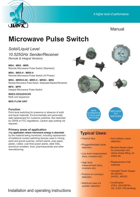
A higher level of performanceMicrowave Pulse SwitchManualSolid/Liquid Level10.525GHz Sender/ReceiverRemote & Integral VersionsMRA - MRS - MRRRemote Microwave Pulse Switch (Standard)MRA - MRS-H - MRR-HRemote Microwave Pulse Switch (Hi Power)MRA - MRRH3-00 - MRR-H - MRSH - MRSRemote Microwave Pulse Switch. Shiploader/Stacker/ReclaimerMPS - MPRIntegral Microwave Pulse SwitchMSEQ SEQUENCERMulti unit sequencerMDS FLOW UNITFunctionPoint level switching for presence or absence of solidand liquid materials. Environmentally and personallysafe replacement for nucleonic switches. Not restrictedby OSHA or FCC regulations. Caution sign posting notrequired.Primary areas of applicationAny application where microwave energy is absorbedby the material being monitored, including replacementof traditional contact switching devices used in mining,sand and gravel quarries, cement plants, pulp paper,plastic, rubber, coal fired power plants, steel mills,aluminium smelters, food, pharmaceuticals and othermanufacturingInstallation and operating instructionsSAFEALTERNATIVETO NUCLEARSWITCHESTypical Uses:• Flow/no flow.• Plugged/blocked chutedetection.• Low level measurement(bins, crushers etc).• High levelmeasurement (bins,crushers etc).• Product on conveyordetection.• Rail/truck load outposition detection.REPLACESTILTSWITCHES• Anti-collision cranedetection.• Blocked feeder pipesfor pneumatic anddense phase filling, airslides etc.• Replacement of tiltswitches.• Versatile Power Supply90-250VAC24VDC, 48VDC.• CertificationATEX, SAA/IECEx,CE, (CSA, FM pending)
Microwave Pulse Switch - Presence & Absence DetectionMANUALRev 1.0IntroductionProprietry NoticeThe information contained in this publication is derived inpart from proprietary and patent data. This informationhas been prepared for the express purpose of assistingoperating and maintenance personnel in the efficient useof the instrument described herein.Publication of this information does not convey anyrights to use or reproduce it, or to use for any purposeother than in connection with the installation, operationand maintenance of the equipment described herein.WARNINGThis instrument contains electronic components thatare susceptible to damage by static electricity. Properhandling procedures must be observed during the removal,installation, or handling or internal circuit boardsor devices.Handling Procedure1. Power to unit must be removed.2. Personnel must be grounded, via wrist strap or othersafe, suitable means before any printed circuit board orother internal device isinstalled, removed or adjusted.3. Printed circuit boards must be transported in a conductivebag or other conductive container. Boards mustnot be removed from protective enclosure until the immediatetime of installation. Removed boards must beplaced immediately in a protective container for transport,storage, or return to factory.Comments:This instrument is not unique in its content of ESD (electrostaticdischarge) sensitive components. Most modernelectronic designs contain components that utilize metaloxide technology (NMOS, CMOS, etc.). Experiencehas proven that even small amounts of static electricitycan damage or destroy these devices. Damaged components,even though they appear to function properly,exhibit early failure.Table of ContentsPrinciple of Operation 3Specifications:Remote 4Integral 5Doppler 7Facial Descriptions:Remote 8Integral 9Doppler 10Applications 11Special Application 12Mounting 13System Wiring, Setup & Calibration 18Dimension Drawings & Diagrams 19Sequencer Installation 27Troubleshooting 28Safety Information 33Warranty 33Part Numbering 34Specifications 36
Microwave Pulse Switch - Presence & Absence DetectionMANUALRev 1.0Principle of OperationREMOTE SYSTEMThe <strong>Hawk</strong> Microwave Pulse Sender-Receiver RemoteSystem is comprised of three electrically isolated units:-the Sender, Receiver and Amplifier. The sender-receiverunits are mounted facing each other. For best performanceit is essential that they be mounted securelyand correctly aligned.The sender emits a burst of microwave energy towardthe receiver, which is designed around a tuned microwavedetector. This burst of energy is transmittedapproximately 200 times each second. While the line ofsight is interrupted by a sufficiency reflective or absorbentmaterial the energy will not reach the receiver, andtherefore the receiver will not detect the transmission.The receiver is designed to switch a relay when it’sdetector changes state. Time delays between detectorchange and relay switching is set via two single turnpotentiometers; there is a potentiometer for the make(signal detected) delay and another for the break (signalinterrupted) delay. In each case the relay will switch onlyafter the detector state has been maintained (since it’schange) for the respective time: any further change ofstate during a time-out period will override the previouschange.The sensitivity of the detector is adjusted by a potentiometer.By this adjustment, compensation can be made forpartially reflective or partially absorbing materials. Similarly,it can be adjusted so that it will change state whenonly a fraction of the beam is blocked. There are twosensitivity adjustment potentiometers, one for a coarseadjustment and the other for a fine adjustment.In the Amplifier unit there are three LED lamps; one indicatesthat power is applied, another indicates that a validsignal is detected, and the other indicates that the relayis energized. In the sender unit the only lamp is the oneindicating that power is applied.INTEGRAL SYSTEMThe <strong>Hawk</strong> Microwave Pulse Sender-Receiver IntegralSystem was created for process control applicationsrequiring highly reliable non-contact absence/presencemonitoring. The flexibility of the system allows for notonly point level indication, but also flow/no flow, proximitysensing, absence/presence and plug chute detection inmany different processes.The Integral system consists of the Microwave PulseSender (MPS) unit and Microwave Pulse Receiver(MPR) unit. Each unit can be powered by 115Vac/240Vac or 24Vdc, mounted by flange or 3”NPT weldmentand is provided in an SM listed NEMA 4X enclosurefor maximum flexibility.The MPS unit has one LED indicator for power and a100mA/250Vac fuse. It also has a TEST push-buttonfor ease of setup and troubleshooting. Inside the MPR,there are three LED indicators for the following: power,signal detect and relay energized indications as well as auser accessible 100mA/250Vac fuse.The MPS unit contains a tuned microwave diode thatemits a continuous stream (approximately200 burstseach second) of microwave energy towards the MPRunit. The MPR contains a tuned microwave detectorwhich will only accept signals from the MPS. When thesender and receiver are mounted in a direct line of sightand correctly aligned, the receiver will detect interruptionsof these bursts. In effect, there is a microwavebeam between the sender and receiver. While the lineof sight is clear, the MPR will detect an uninterruptedstream. When the beam is interrupted by a sufficientlyconductive material, the receiver detector will sense theinterruptions and change states. This change of detectorstates activates the relay, thus giving the basis forabsence/presence indication.Sensitivity of the receiver in the MPR is controlled by twosingle turn potentiometers: one for fine adjustment andthe other for coarse adjustment. The sensitivity adjustmentallows for compensation when monitoring partiallyconductive material. Similarly, it can be adjusted so thatit will change state when only a fraction of the beam isinterrupted.The SPDT relay of the MPR unit can be set to eitherenergize or de-energize when the beam is broken. Thisselection is made via the two-position slide switch nextto the power input terminals.The MPR unit also contains two time delays for controllingand fine tuning its relay operation: the make (signaldetected) and break (signal interrupted) adjustments.Each delay is independently adjustable by a single turnpotentiometer from 100ms to 30 seconds. The relay willswitch only after the detector state (signal/no signal)has been maintained for the time specified by the setpoint on the potentiometer. Any time there is a change inSultanstate,234theSeriestimers are automatically reset.For a more detailed list of specifications, please refer tothe Specifications section of this manual.Microwave Series
Microwave Pulse Switch - Presence & Absence DetectionMANUALRev 1.0Principle of OperationSpecifications - RemoteMDS DOPPLER SYSTEMRemote - MPA MRS/MRR MRS-H/MRR-HThe <strong>Hawk</strong> MDS series microwave doppler flow switchwas developed for use in process applications requiringhighly reliable non-contact product flow detection. Thesystem operates bysending out bursts of microwaveenergy toward the target product being monitored. Thetarget product will reflect some of the microwave energyback to the MDS system where it is processed to determineif the product is flowing.The MDS system uses the Doppler principle to determineif the product is moving by monitoring smallcharges in the reflected signal frequency. When productflow is detected, a timer is initiated and after the user settime-out period, the relay output is switched. The systemalso has adjustable sensitivity to compensate forproducts that may partially reflect the microwave energy.The SPST relay can be set to either energise or de-energisewhen product flow is detected. Three LED indicatorsare provided to indicate power, flow detection, and relayenergised status.The system is available in either an integral or remotehousing and is powered by 115Vac, 240Vac or 24Vdc.The system is housed in a FM listed NEMA 4X housingand is mounted using the standard 3 inch NPT weldmentor flange.Input Voltage:240Vac nominal, 200-270Vac acceptable, 50-60 Hz115Vac nominal, 100-130Vac acceptable, 50-60 HzAC supply line fuse: 100mA, 250VacAmplifier unit includes terminals for 24Vdc power supplyPower Consumption:MRA
Microwave Pulse Switch - Presence & Absence DetectionMANUALRev 1.0Specifications - IntegralSpecifications Remote (con’t)Adjustments:MPS: Test switch - momentary push-buttonMPR: Single turn coarse and single turn fine adjustmentpotentiometers for set point.Relay time delays adjustable from 100msto 30 seconds via two independenton/signal make and off/signal breakpotentiometers with automatic reset.Fall-safe:Switch selectable - presence or absence ofmaterial.High level fail-safe position: relay is activated when materialis presentLow level fail-safe position: relay is activated when nomaterial is presentTemperature:MPS & MPR: -30°C to +65°C (-20°F to +150°F) Note: forhigher temperature applications, remote mounting withwindows is necessary. Customwaveguide assemblies can also be provided.UHMW Window: +80°C (+176°F)Ceramic Window: Consult factory formanufacturer’s specifications.Firebrick Assemblies: Consult factory formanufacturer’s specifications.Cabling Entry(ies):MPS: 1 X 10mm (3/8” NPT)MPR: 2 X 10mm (3/8” NPT)Relay Contact Output:MPR: SPDT - 10amps @ 250Vac resistive10amps @ 125Vac resistiveEnclosure:VALOXSAA LISTEDIntegral - MPS - MPRInput Voltage:115Vac nominal, 100-130Vac acceptable, 50-60Hz240Vac nominal, 200-270Vac acceptable, 50-60HzAC supplys lined fuse: 100mA, 250VacBoth MPS & MPR units include terminalsfor 24Vdc supply powerPower Consumption:MPS < 2VAMPR < 3VAPower Density:Rated from emitter (MPS) to receiver (MPR) at approximately20μW/cm . No interconnection wiring betweenemitter and receiver. Complies with FCC Title Rules Part15. Caution sign posting not required.Transmitted Signal:Frequency: 10.525 GHz, + 25 MHzAverage Power Density:20RW/cm2 typical Linearly Polarized FieldBeam angle (3dB) approximately 30 degrees (conservative)Range:Maximum range under ideal conditions: 105m (340 ft.)Expected maximum practical range: 65m (215 ft.)Minimum range under ideal conditions: 10cm (4 in.)Range (cont):Expected minimum practical range: 20cm (8 in.)Note: Minimum ranges are dependent onapplication conductivity.L.E.D. Indicators:MPS: power on (green)MPR: power on (green), signal detect (red), relay state(amber)Mounting:1. 3” male NPT thread or four 6mm (.250in.) blind boltholes in flange.a) 3” weldments supplied for standard integral mounting.b) Flange is used for remote mount in high vibration applications- isolation shock mounts are available.Sultan 2. 4” weldments 234 Serieswith PTFE (teflon), UHMW, ceramic,firebrick windows.3. Ceramic window assemblies - rectangular.4. Firebrick window assemblies available on custombasis - rectangular - circular.5. 2” NPT sight glass window.6. Waveguides - custom assemblies available.Microwave Series
Microwave Pulse Switch - Presence & Absence DetectionMANUALRev 1.0Specifications Integral - MPS - MPR (con’t)Input Voltage:115Vac nominal, 100-130Vac acceptable, 50-60Hz240Vac nominal, 200-270Vac acceptable, 50-60HzAC supplys lined fuse: 100mA, 250VacBoth MPS & MPR units include terminals for 24Vdc supplypowerPower Consumption:MPS < 2VAMPR < 3VAPower Density:Rated from emitter (MPS) to receiver (MPR) at approximately20μW/cm . No interconnecting wiring betweenemitter and receiver. Complies with FCC Title Rules Part15. Caution sign posting not required.Transmitted Signal:Frequency: 10.525 GHz, + 25 MHzAverage Power Density:20RW/cm2 typical Linearly Polarized FieldBeam angle (3dB) approximately 30 degrees (conservative).Range:Maximum range under ideal conditions: 105m (340 ft.)Expected maximum practical range: 65m (215 ft.)Minimum range under ideal conditions: 10cm (4 in.)Expected minimum practical range: 20cm (8 in.)Note: Minimum ranges are dependent onapplication conductivity.L.E.D. Indicators:MPS: power on (green)MPR: power on (green), signal detect (red), relay state(amber)Mounting:1. 3” male NPT thread or four 6mm (.250in.) blind boltholes in flange.a) 3” weldments supplied for standardintegral mounting.b) Flange is used for remote mount in highvibration applications - isoiation shockmounts are available.2. 4” weldments with PTFE (teflon), UHMW, ceramic,firebrick windows.3. Ceramic window assemblies - rectangular.4. Firebrick window assemblies available on custombasis - rectangular - circular.5. 2” NPT sight glass window.6. Waveguides - custom assemblies available.Adjustments:MPS: Test switch - momentary push-buttonMPR: Single turn coarse and single turn fine adjustmentpotentiometers for set point.Relay time delays adjustable from 100ms to 30 secondsvia two independent on/signal make and off/signal breakpotentiometers with automatic reset.Fall-safe:Switch selectable - presence or absence of material.High level fail-safe position: relay is activated when materialis present.Low level fail-safe position: relay is activated when nomaterial is present.Temperature:MPS & MPR: -30°C to +65°C (-20°F to +150°F)Note: for higher temperature applications, remote mountingwith windows is necessary. Custom waveguide assembliescan also be provided.UHMW Window: +80°C (+176°F)Ceramic Window: Consult factory for manufacturer’sspecifications.Firebrick Assemblies: Consult factory for manufacturer’sspecifications.Cabling Entry(ies):MPS: 1 X 10mm (3/8” NPT)MPR: 2 X 10mm (3/8” NPT)Relay Contact Output:MPR: SPDT - 10amps @ 250Vac resistive10amps @ 125Vac resistiveEnclosure:VALOXSAA LISTEDMeets Class 2, Div 1, Group E, F & G (DlP-Dust IgnitionProof) classification.FM Approval Pending.Windows: UHMW (ultra-high molecular weight) polyethylenestandard PTFE (teflon) available,(see part numbering).Sealing:IP67 (NEMA 4X)Shipping Weights:MPS: 4.5kg (10 lbs.)MPR: 4.5kg (10 lbs.)
Microwave Pulse Switch - Presence & Absence DetectionMANUALRev 1.0Specifications - Doppler SwitchDoppler Switch - MDSInput Voltage:240Vac nominal, 200-270Vac acceptable, 50-60 Hz115Vac nominal, 100-130Vac acceptable, 50-60 HzAC supply line fuse: 100mA, 250VacUnits have terminals for 24Vdc supply power.Power Consumption:
Microwave Pulse Switch - Presence & Absence DetectionMANUALRev 1.0Facial Description Layout - RemoteFine Sensitivity PotCoarse Sensitivity PotL.E.D. IndicatorsGreen - PowerRed - SignalAmber - RelayRV1(A=B)RV2RECEIVESENSITIVITYLOLOHIHISerial No. MXXXXXXXMPR-0MICROWAVE PULSE RECEIVERLD1 -LD2 -LD3 -POWERAPPLIEDSIGNALDETECTEDRELAYENERGISEDAFTER DELAY110.30.3RELAYNORM44Serial Number10ONDELAY-30 secRV210OFFDELAY-30 secOn DelayOff DelayTest SwitchTS4 TerminalsTS3 TerminalsPAC FUSER S T100mAU V WFROMMPSCTIVEEUTRALARTHANEEARTH+24VREVTOMPS100mA Fuse (F1)EXTEND CABLEBELDEN #9512(Max. 50metres)RelayNormal/ReverseEXTEND CABLEBELDEN #9363(Max. 50 metres)TS1AC Supply (TS1)Active 240 (Hot)NeutralEarth GroundNormally Closed (TS2)Common Output Contacts (TS2)Normally Open (TS2)DC Supply (TS1)+24V (Hot)Earth Ground } TS1Polyester coatedmild steel pipeRECEIVERMPR-0SENDERMPS-03" N.P.T.1" N.P.T.3" N.P.T.1" N.P.T.TS3 provides power to and accepts signals from the RemoteMPR-0. The MPR receives Microwave signals from the MPS.P = OV (Black) T = Remote Rx Power (Red)R = Rx Sig- (Blue) S = Rx Sig+ (Yellow)TS4 provides power and transmits signals to the Remote MPS-0.The MPS sends the Microwave signals to the MPR.U = OV (Black) V = Tx Sig- (Blue) W = Remote Tx Power (Red)NOTE: Maximum cable length including extension is 50 metres each for MPS and MPR.
Microwave Pulse Switch - Presence & Absence DetectionMANUALRev 1.0Facial Description Layout - IntegralMPS - SENDERL.E.D. IndicatorsGreen - PowerSerial No. MXXXXXXXMPS-0MICROWAVE PULSE SENDERLD1 - POWERAPPLIEDDCINPUTSerial Number+24V4 OVAC FUSE100mACTIVEEUTRALARTHANETESTTest Switch (SW1)(cancels MPS transmission)100mA Fuse (F1)DC Supply (TS2)AC Supply (TS1)Active 240 (Hot)TS1 NeutralEarth GroundOV (Ground)+24VNot UsedMPR - RECEIVERL.E.D. IndicatorsGreen - PowerRed - SignalAmber - RelayFine Sensitivity PotSensitivity Lo/Hi SwitchEMI IndicatorAlignmentindicator0–2.8VdcCoarse Sensitivity PotTP5 PositiveTP6 GndRV1RECEIVESENSITIVITYLO(A=B)RV2LOHIHISerial No. MXXXXXXXMPR-0MICROWAVE PULSE RECEIVER1LD1 - POWERSENS.APPLIEDLO HILD2 - SIGNALDETECTED 0.3AC FUSE100mACTIVELD3 -EUTRALARTHE ARTHANERELAYENERGISEDAFTER DELAY+24V10.3RELAYNORMREV4410ONDELAY-30 secRV210OFFDELAY-30 secSerial NumberOn DelayOff DelayRelayNormal/Reverse100mA Fuse (F1)Sultan 234 SeriesAC Supply (TS1)Active 240 (Hot)TS1 NeutralEarth GroundNormally Closed (TS2)Common Output Contacts (TS2)Normally Open (TS2)DC Supply (TS1)+24V (Hot)Earth Ground} TS1Microwave Series
Microwave Pulse Switch - Presence & Absence DetectionMANUALRev 1.0Facial Description - Doppler SwitchSensitivity 'A' PotSensitivity 'B' PotL.E.D. IndicatorsGreen - PowerRed - SignalAmber - RelayEMI Indicator(TS3) Terminals(TP5) Positive(TP6) GndRV1(A=B)RV2RECEIVESENSITIVITYLOLOP R S TRXHIHISerial No. MXXXXXXXMDAMICROWAVE PULSE RECEIVER1AC FUSE100mACTIVELD1 -LD2 -LD3 -EUTRALANEPOWERAPPLIEDSIGNALDETECTEDRELAYENERGISEDAFTER DELAYARTHE ARTH+24V10.30.3RELAYNORMREV44Serial NumberOn Delay10Off DelayONDELAY-30 secRV210OFFDELAYTest Switch-30 secP = OV (Black)S = Rx Sig (Blue)T = Remote Rx Power (Red)(Remote Version only)100mA Fuse (F1)Relay modeEXTEND CABLEBELDEN #9512(Max. 50 metres)TS1To remote RX/TX Module(Remote Versions only)AC SupplyActive 115/240VacNeutralEarth GroundNormally ClosedCommon Output ContactNormally OpenDC SupplyRelay Terminals (TS2)+24V (Hot)Earth Ground} TS1Remote RX/TX ModulePolyester coated steelMDR1" BSPNipple3" N.P.T.NOTE: Maximum cable length including extension is 50 metres.10
PPRV1(A=B)RV2RV1(A=B)RV2LOLOHIHISerial No. MXXXXXXXMICROWAVE PULSE RECEIVERLD1 - POWERAPPLIEDLD2 -LD3 -SIGNALDETECTEDRELAYENERGISEDAFTER DELAY110.3RELAYNORM44-30 sec-30 secREVAC FUSER S T100mAU V WTOMPSFROMMPSLOLOHIHIA CTIVEN EUTRALE ARTHSerial No. MXXXXXXX+24VMICROWAVE PULSE RECEIVERLD1 - POWERAPPLIEDLD2 -LD3 -SIGNALDETECTEDRELAYENERGISEDAFTER DELAY110.3RELAYNORM0.344-30 sec-30 secREVAC FUSER S T100mAU V WTOMPSFROMMPSA CTIVEN EUTRALE ARTH+24V0.310101010RV2RV2PRV1(A=B)RV2LOLOHIHISerial No. MXXXXXXXMICROWAVE PULSE RECEIVERLD1 - POWERAPPLIEDLD2 -LD3 -SIGNALDETECTEDRELAYENERGISEDAFTER DELAY110.3RELAYNORM44-30 sec-30 secREVAC FUSER S T100mAU V WTOMPSFROMMPSA CTIVEN EUTRALE ARTH+24V0.31010RV2PRV1(A=B)RV2RECEIVESENSITIVITYLOLOHIHISerial No. MXXXXXXXMICROWAVE PULSE RECEIVERLD1 - POWERAPPLIEDLD2 -LD3 -A CTIVEN EUTRALE ARTHSIGNALDETECTEDRELAYENERGISEDAFTER DELAY+24VE ARTH110.30.344-30 secRV210OFFDELAY-30 sec10ONDELAYRELAYNORMREVAC FUSER S T100mAU V WFROMMPSTOMPSPPRV1(A=B)RV2RV1(A=B)RV2LOLOHIHISerial No. MXXXXXXXMICROWAVE PULSE RECEIVERLD1 - POWERAPPLIEDLD2 -LD3 -SIGNALDETECTEDRELAYENERGISEDAFTER DELAYA CTIVEN EUTRALE ARTHE ARTH+24V110.30.3RELAYNORM44-30 sec-30 secREVAC FUSER S T100mAU V WTOMPSFROMMPSLOLOHIHISerial No. MXXXXXXXMICROWAVE PULSE RECEIVERLD1 - POWERAPPLIEDLD2 -LD3 -SIGNALDETECTEDRELAYENERGISEDAFTER DELAYA CTIVEN EUTRALE ARTHE ARTH+24V110.30.3RELAYNORM44-30 sec-30 secREVAC FUSER S T100mAU V WTOMPSFROMMPS10101010RV2RV2Microwave Pulse Switch - Presence & Absence DetectionMANUALRev 1.0ApplicationsTypical Microwave Applications• Feeder pipe coal/ore• Flow/no flow• Blocked chuteReceivingunitSolid Level - Cyclone BinHigh/Low LevelRECEIVESENSITIVITYMPR-0E ARTHONDELAYOFFDELAYReceiving unitHigh LevelSendingUnitRECEIVESENSITIVITYHighMPR-0ONDELAYOFFDELAYRECEIVESENSITIVITYMPR-0E ARTHONDELAYOFFDELAYReceiving unitLow LevelSendingUnitReceivingunitSendingUnitRECEIVESENSITIVITYLowMPR-0ONDELAYOFFDELAYBlocked Chute DetectorReceiving unitRECEIVESENSITIVITYMPR-0ONDELAYOFFDELAYE ARTHSending UnitProduct Movement/Flow DetectionConveyorMoving producton conveyorsFlow detectionFlowing solids /powdersConveyorMoving product onconveyorsMoving producton conveyorsSultan 234 SeriesCoal FeederMDSMPR-011Microwave Series
ANEMicrowave Pulse Switch - Presence & Absence DetectionMANUALRev 1.0Special ApplicationBoom Protection For Shiploaders, Stackers,ReclaimersEquipment: Microwave Pulse Switch.To eliminate the cancellation signals simply and still providea microwave sender/receiver combination that wassimple to set up and calibrate, we designed hardwareinto a slightly larger Receiver housing that overcame thecancellation signal effects.Type:Type:MRA Microwave Remote AmplfierMRS Microwave Remote SenderMRRH3 Microwave Remote Receiver SpecialMPS Microwave Pulse Sender (Integral Version)MPRH3 Microwave Pulse Receiver Special (Integral Version)Using the MRRH3 or the MPRH3 Receiver will stillallow the instrument to detect small enough targetslike a 50mm guard rail for the shiploader, but has alsoincreased the maximum range to 150 metres using thesender units, MRS and the MPS. If the MRS-H and theMPS-H High powered sender versions were used thenthe maximum range extends beyond 250 metres.The <strong>Hawk</strong> “special” Microwave Pulse Receiver has beenspecially designed for the use of “Boom Protection Applications”,for Shiploaders, Stackers and Reclaimers willoperate using the standard Microwave sender and amplifier,or the High powered versions.<strong>Hawk</strong> has noted that with different boom designs andespecially telescopic mechanical configurations on shiploaders,that there were times when cancellation signalsappeared, turning the instrument off, when clearly, thepath between the sender and receiver, were clearly notblocked.Wiring specifications remain the same for all Microwaveversions, remote and integral systems.The Boom Protection Microwave system will obiviouslywork under heavy rain, fog, dusty enviro-ments for Shiploader,Reclaimer or Stacker applications.Fine Sensitivity PotCourse Sensitivity PotL.E.D. IndicatorsGreen - PowerRed - SignalAmber - RelayRV1(A=B)RV2RECEIVESENSITIVITYLOLOHIHISerial No. MXXXXXXXMPR-0MICROWAVE PULSE RECEIVERLD1 - POWERAPPLIEDLD2 -LD3 -SIGNALDETECTEDRELAYENERGISEDAFTER DELAY110.30.3RELAYNORM44-30 sec-30 secSerial Number10ONDELAYRV210OFFDELAYOn DelayOff DelayTest SwitchTS 4 Terminals6" ANSI Flange Notch Alignment IndicatorUHMW WindowTS3TerminalsPREVAC FUSER S T100mAU V WFROMMPSCTIVEEUTRALARTHE ARTH+24VTOMPS238.0100mA Fuse (F1)EXTEND CABLEBELDEN #9512(Max. 50metres)RelayNormal/ReverseEXTEND CABLEBELDEN #9363(Max. 50metres)TS1AC Supply (TS1)Active 240 (Hot)NeutralEarth GroundNormally Closed (TS2)Common Output Contacts (TS2)Normally Open (TS2)DC Supply (TS1)+24V (Hot)Earth Ground } TS1Note: 48 VDC Optional15.0mm (0.6")4 x 22.0 holes thruequi-spaced onP.C.D. 241.0mm1" BSP nippleMild steelPowder coat finnish1" BSP nipple280.0mm (11")230.0mm (9")10.0m Cable standard165.5mm (6.5")10.0m Cable standardRECEIVERMRRH3-00SENDERMRSH-00MRS-0012
Microwave Pulse Switch - Presence & Absence DetectionMANUALRev 1.0MountingGeneral Guidelines1. The microwave beam is a polarized form of energy.As such, it is necessary to align the units in the samespatial plane. If the units do not have the same orientationthe amount of received energy is diminished. At 90°to each other, the detector is blind and cannot detect thebeam. The actual angle of mounting is not relevant, solong as both the MPS & MPR have the same angle andelevation.See figure B.2. When looking for a mounting location, try to locateand mount the units flush and where minimal buildupwill occur. The system can penetrate through generousamounts of buildup of various products; however, thebetter the position, the more reliable it will operate.3. The systems energy cannot penetrate through steellinings or other conductive linings. You must cut a viewingwindow and use an appropriate weldment.4. For high vibration applications, it is necessary to isolatethe electronics to keep them from being damaged.This is accomplished using the optional 4” UHMW or teflonwindows. The microwave sender and receiver shouldbe mounted to a stable structure (I-beam, handrail) toisolate them from the vibration. Isolation shock mountscan also be provided to help isolate the electronics.See Figure C.5. For applications which exceed 140 degrees Fahrenheit(precipitators, cement cyclones, etc.), it is necessaryto use remote mounting microwaves with waveguideassemblies. This allows the electronics to be placed inan area where ambient temperatures do not exceedthe maximum allowable temperature for the electronics.Firebrick and ceramic windows are best suited for hightemperature applications. It is necessary to contact thefactory for this type of application, however, Figure D isprovidedas a general guideline for such applications.MDS Doppler System1. Mount the MDS in an area where the product flow is tobe monitored.2. Ensure there is low vibration on the mounting if theproduct flow is low.3/ Mount the MDR sender-receiver in a position wherestationary material will not build upon the sensor face.Ensure the face of the sensor is flush with the inside ofthe flow chamber. (if used in a closed environment)4. Correctly wire the MDR to the MDA as per the connectiondiagram. If extension cableis used, S and T aresingle cables. The remainder are all then combined toform a solid ground connection back to terminal labelledP.5. RV1 and RV2 must be adjusted together with thepotentiometer positional arrows both basically alignedin the same direction. They are parallel potentiometers.Begin at minimum anti-clockwise position.6. Position Lo-Hi slide switch to low position.7. Apply power to the unit. The green LED LD1 will beilluminated.8. When material is flowing at normal speed, slowly increaseRV1 and then RV2, then RV1 then RV2 etc. untilflow is detected. Flow is detected when the Red LEDLD2 is illuminated.9. The yellow LED, LD3 will be illuminated when therelay becomes energised.10. The relay energisation is timed via an ON delay andOFF delay potentiometers ON delay is the delay whenLD2 is constantly illuminated prior to the relay pulling in.When LD2 is no longer illuminated (i.e. no flow) the delaybefore the relay switches off is controlled by the OFFdelay potentiometer.11. When LD2 is illuminated increase RV1 and RV2 by afurther 15% (approx.) of the adjusted distance from thezero position. This allows for some variation in the flowindeed - the larger the percentage used the greater theflow change needed before the relay switches.12. Intermittent flow surges can be removed via the ONdelay OFF delay potentiometers13. If you increase RV1 and RV2 to maximum and LD2is not illuminated, decrease anti-clockwise back to zero.Slide the slide switch LO-HI to the Hi position and repeatthe slow step by step adjustment of RV 1 and RV2.Sultan 234 SeriesIf possible stop the flow to ensure the sensitivity (RV1and RV2) are set correctly. The time delays can bechecked without stopping the flow of the material. Thepush button on the RHS of the board is a press to testpush button. This simulates no received flow signal andconsequently you can adjust your on and off delays.13Microwave Series
Microwave Pulse Switch - Presence & Absence DetectionMANUALRev 1.0MountingGENERAL GUIDELINES cont’dFigure A: Mounting AnglesFigure B: 1. MPS/MPR Beam ElevationSending Unit ( MPS)Microwave BeamReceiving Unit ( MPR)Correct ElevationMaximum Signal Strength to ReceiverSending Unit (MPS)Receiving Unit (MPS)Incorrect ElevationMinimum Signal Strength to Receiver14
Microwave Pulse Switch - Presence & Absence DetectionMANUALRev 1.0MountingSpecific ApplicationsFigure E - Mounted as Block Chute Switch1. When mounting to monitor in a flowing product suchas coal, ore or wood chips, position the microwave pathout of the direct flow stream. If at all possible, go behindthe flow stream or well in front of the flow stream.This will prevent any possibility of unwanted trips due toabnormal product flow from the conveying system. SeeFigure E.2. When mounting to monitor for absence/presenceor plugged chute conditions, the MPS & MPR must bemounted opposite each other observing correct elevationand orientation. The system should be mounted in sucha way so that as product backs up, the beam will bebroken. Refer to Figure E for an example.Receiving Unit(MPR)PRODUCT FLOW3. When mounting to monitor flow/no flow and pluggedchute conditions, one MDS and one MPS/MPR unitsmust be used. The MPS and MPR provide the pluggedchute detection and are mounted opposite each otherin the same manner as the standard plugged chutedetection arrangement. The MDS however, is mounteddirectly above the MPR unit.4. When using the system as a proximity switch, themounting arrangement is application dependent andmust ensure proper operation even under worst caseconditions.Please consult your representative or the factory forspecific mounting arrangements.5. Mounting of the Microwave Pulse system on slopedvessel walls can be accomplished using the MicrowaveAdjustable Mount. This system allows the microwavesto be mounted to a sloped surface and then adjustedhorizontally for optimum performance and operation.The adjustable mount has an integral 4” weldment withUHMW polyethylene or PTFE (teflon) window options.Also included with the bracket is a vibration isolationkit (shock mounts) to help protect the electronics fromdamage. Each side wall of the vessel must not exceed30 degrees from the vertical centerline. To mount theadjustable bracket, simply weld the 4” weldment directlyto the vessel, install the window, mount the microwaveand adjust horizontally.See Figure G (page 11).Figure F: Flow/No FlowSultan 234 SeriesPRODUCTFLOWSending Unit(MPS)MDS Flow / No FlowSwitch15Microwave Series
Microwave Pulse Switch - Presence & Absence DetectionMANUALRev 1.0MountingFigure C: High Vibration FlangeMounting DetailReceiving Unit (MPR)Product FlowCustomerSuppliedMountingBracketFlange Mounted to anIsolated Permanant SupportStructure i.e.I-Beam,and Rail, etc., forHigh Vibration Applications.Microwave should be awayfrom normal material flow.Note: Distance betweenmicrowave face and windowshould not exceed 75mm (3")for all applications(UHMW/PTFE Windows,Sight Glass, Ceramic Brickand Firebrick assemblies).Sending Unit(MPS)Stable SupportStructureFigure D: High Temperature RemoteHopper/Feeder (Not to Scale)Ceramic or Firebrick AssemblyW/Antenna Support BracketHigh Temperature Area(Ambient Higher than 140° )Wave GuidesNormal Temperature Area(Ambient Lower than 140° )MPR RemoteMPS Remote16
Microwave Pulse Switch - Presence & Absence DetectionMANUALRev 1.0MountingSpecific Applications Mounting cont'dFigure G: MPS/MPR and MRS/MRR Adjustable MountProduct FlowHooper/FeederIsolation MountXXX = 30°MaximumSending Unit(MPS)Receiving Unit(MPR)Adjustable microwavemounting bracketwelded to vessel wall.W / UHMW or TeflonWindowSultan 234 Series17Microwave Series
Microwave Pulse Switch - Presence & Absence DetectionMANUALRev 1.0System Wiring, Setup & CalibrationWiringWhile there is no interconnecting wiring required for themicrowave system, care must be taken to ensure thateach unit’s individual wiring is correct prior to applyinginitial power. Reference Figure A for specific termination’son each unit.1. The MPS is supplied with one 10mm (3/8” NPT) conduitentry hole pre-drilled in the enclosure while the MPRhas two 10mm (3/8” NPT) entry holes. The MRA hasthree 10mm (3/8” NPT) entry holes.2. The only wiring required by the MPS unit is that of inputvoltage. This is accomplished using the TS1 terminalblock and 16AWG wire or larger.3. The MPR will require relay wiring as well as inputvoltage wiring. This is accomplished using terminal blockTS1 for the input voltage and terminal block TS2 for therelay. All terminations require 16AWG wire or larger.4.The MRA is wired similarly to both MPS and MPR (seeconnection diagram for details)Setup & Initial CalibrationAfter completing the mounting and wiring procedures itwill be necessary to perform initial checks of the system.These checks include the following:1. Verify that the units are mounted securely and that theconduit entry angles and elevation are the same. Alsocheck to verify there is a clear line of sight between theSender and Receiver units.2. Ensure that all wiring is correct and that there are nobare wires protruding from the terminal connectors onthe units. Check the input supply voltages prior to connectingit to the units.Once you are satisfied with the installation, apply powerto the system and perform the following checks. If theanswer to any question is NO, then go to the troubleshootingsection of this manual.1. Is the power indicator (LD1) on both the MPS/MPR &MRA showing green?4. Toggle the relay normal/reverse switch (SW1) on theMPR. Does the relay energized indicator (LD3) go onand off with respect to the movements of SW1 ?Once you have completed the above checks, it will thenbe necessary to adjust the MPR/MRA for your particularprocess. With a clear line of sight between the Senderand Receiver, turn both potentiometers A & B fully counter-clockwise.1. The signal detect (LD2) will turn off. Slowly turn bothA & B together in a clockwise direction until the signaldetect indicator (LD2) begins to flicker. From this point,itis essential to move potentiometer A extremely slowas it is a fine adjustment. Further adjust potentiometerA clockwise just to the point where LD2 stays on steadywithout flickering.2. Next, adjust both time delay potentiometers to the 12o’clock position. Break the beam if possible. It is preferablethat this is done via the application but for initialadjustment of the delays you can simulate the beambeing blocked by depressing the TEST push-button onthe MPS unit. This will stop (interrupt) transmission ofthe beam.3. Adjust the ON DELAY to obtain the desired delayafter the TEST push-button is released. Adjust the OFFDELAY to obtain the desired delay after the TEST pushbuttonis depressed.4. Set SW1 on the MPR unit for the desired relay energizationmode. NORM will provide an energized relaywhile the signal is detected and REV will provide anenergized relay when the signal is lost.5. If the product fails to break the beam, adjust the sensitivitycounter-clockwise until the signal detect (LD2) lightgoes out, then adjust approximately 1/10 of a turn furthercounter-clockwise.If the set-up was completed without product, it may benecessary to make final adjustments with the processrunning and product moving between the Sender/Receiverunits. The hi-lo sensitivity should be left on hi.If the product fails to block the beam, you should thenrevert to the lo sensitivity setting.2. On the MPR, turn potentiometers A & B fully clockwise.Is the signal detect indicator (LD2) showing red?3. Have someone else depress the TEST push-buttonon the MPS while you watch the signal detect (LD2) onthe MPR/MRA. Does the indicator go on and off withrespect to the TEST push-button?18
Microwave Pulse Switch - Presence & Absence DetectionMANUALRev 1.0Drawing AMICROWAVE REMOTE AMPLIFIER (MRA) - Overall Dimensions4 x 5.0mm holes25.5mm (1") 61.5mm (5.4")160mm (6.3")135mm (5.25")137mm (5.4")25.5mm(1")61.5mm(5.4")61.5mm(5.4")25.5mm(1")145mm (5.7")61.5mm (5.4") 25.5mm (1")170mm (6.8")MICROWAVE REMOTE SENDER/RECEIVER (MRS/MRR) - Overall Dimensions3" N.P.T.Polyester coated mild steel pipe1" BSP nipple135mm (5.25")160mm (6.3")UHMWWindow130mm (5")192mm (7.6")4 x 5.0mm holes25.5mm (1") 61.5mm (5.4")Polypropylene housing and flange137mm (5.4")61.5mm(5.4")25.5mm(1")25.5mm(1")61.5mm(5.4")XXXmm (X.X")175mm (6.9")1" BSP nipple61.5mm (5.4") 25.5mm (1")237mm (9.3")MICROWAVE REMOTE SENDER/RECEIVER - HIGH POWER (MRS-H/MRR-H)Overall Dimensions6" ANSI Flange6" (150mm)Polyester coated mild steel pipe15mm(0.6")1" BSP nipple165mm (6.5")Sultan 234 Series230mm (9")15mm (0.6")4 X Ø22.0 holes thru equispaced on 241 P.C.D.UHMW Window280mm (11")19Microwave Series
Microwave Pulse Switch - Presence & Absence DetectionMANUALRev 1.0Drawing BMICROWAVE PULSE SENDER/RECEIVER (MPS/MPR) - Overall Dimensions3" N.P.T.160mm (6.3")135mm (5.25")85mm(3.35")145mm(5.7")135mm(5.25")160mm(6.3")4 X Ø22.0 holes thru equispaced on 241 P.C.D.130mm(5.15")310mm(12.2")MICROWAVE PULSE SENDER/RECEIVER (MPS/MPR) - Mounting Plate160mm(6.3")12.7mm R.500 ThruTyp 4 Pics79mm (Ø3.110) Thru160mm(6.3")6mm (Ø.236) ThruOn 132mm (5.232") B.C.12mm (Ø.472)Typ 4 Eq. Sp. Pics.45.00 22.50 9mm (Ø.354) ThruOn 190.5mm (7.5") B.C.Typ 4 Eq. Sp. Pics.20
Microwave Pulse Switch - Presence & Absence DetectionDrawing CMANUALRev 1.0DimensionsRemote Microwave Doppler System - Remote Amplifier (MDA)4 x 5.0mm holes25.5mm (1") 61.5mm (5.4")137mm (5.4")25.5mm(1")61.5mm(5.4")61.5mm(5.4")25.5mm(1")145mm (5.7")61.5mm (5.4") 25.5mm (1")170mm (6.8")Remote Microwave Doppler System - Remote Sensor (MDR)Polyester coated mild steel pipe3" N.P.T.1" BSP nipple160mm (6.3")Integral Microwave Doppler System (MDI)3" N.P.T.160mm (6.3")135mm (5.25")85mm(3.35")145mm(5.7")160mm (6.3")135mm (5.25")135mm (5.25")UHMWWindow130mm (5")192mm (7.6")135mm(5.25")160mm(6.3")4 X Ø22.0 holes thru equispaced on 241 P.C.D.Sultan 234 Series130mm(5.15")310mm(12.2")21Microwave Series
Microwave Pulse Switch - Presence & Absence DetectionMANUALRev 1.0Drawing D3" & 4" Weldment Window147.6mm(Ø5.81)5.1mm(0.20")5.1mm(0.20")3" N.P.T.83.7mm(3.30")4" N.P.T.120.7mm(4.75")5.1mm(0.20")5.1mm(0.20")3" & 4" UHMW Polyethylene/Ceramic Window4" N.P.T.Ø.312 Typ2 Pics3" N.P.T.56.2mm (2.21")25.4mm(1.0")10.2mm (0.40")25.4mm(1.0")10.2mm (0.40")3" & 4" Teflon/Ceramics WindowØ.312 Typ2 Pics3" N.P.T.4" N.P.T.56.2mm (2.21")25.4mm(1.0")10.2mm (0.40")25.4mm(1.0")10.2mm (0.40")22
Microwave Pulse Switch - Presence & Absence DetectionMANUALRev 1.0Drawing ECeramic Heat Shield MountCeramic Brick Mount Assembly152.4mm (6.0")101.6mm(4.0")317.5mm (12.5")Ceramic BrickSultan 234 Series152.4mm (6.0")23Microwave Series
Microwave Pulse Switch - Presence & Absence DetectionMANUALRev 1.0Drawing FIsometric View; Firebrick MountAssembly View; Firebrick Mount228.6mm (9.0")114.3mm(4.5")215.9mm(8.5")419.1mm (16.5")50.8mm(2.0")Firebrick; Firebrick Mount114.3mm(4.5")152.4mm (6.0")76.2mm(3.0")24
Microwave Pulse Switch - Presence & Absence DetectionMANUALRev 1.0Drawing GWaveguide WR90 Cone41mm(1.625")33mm(1.283")41mm(1.625")32mm(1.275")10mm(0.90")23mm(0.890")Waveguide WR90 StraightFBGTAW4mm (Ø.172) ThruTyp 4 Pics33mm(1.283")"A"Note: "A" = Per ApplicationFinish Per Application33mm (1.283")Waveguide WR90 Bend4mm (Ø.172) ThruType 8 Pics 33mm (1.283")FB33mm(1.283")Sultan 234 Series"A"GTAWFBNote: "A" = Per ApplicationFinish Per Application25Microwave Series
Microwave Pulse Switch - Presence & Absence DetectionMANUALRev 1.0Drawing H, IDRAWING HAdjustable Microwave Bracket135mm (5.3")(Ø.400) Thru225mm(8.9")116mm (4.6")147mm (5.8")336mm (13.2")DRAWING IGlass Window2" N.P.T.19.9mm (0.78")6.3mm (0.25")26
Microwave Pulse Switch - Presence & Absence DetectionMANUALRev 1.0Sequencer - InstallationSequencerThe Microwave Pulse Sequencer is powered by mains or24Vdc, it is a self-contained unit which synchronises thepulsing of up to 6 microwave units. Each unit is allocateda unique ‘time slot’ in sequence, in which that unit maytransmit (and receive). This means that no 2 units will beoperating at once, eliminating the possibility of interferencebetween units.SpecificationsPower:110-120 or 220-240Vac50 or 60 Hz or 24VdcOutputs:Active-low with internal 470Ωpull-up to +5vOutput pulse width: 341.3 µSTime between pulses: 5.46mSInternal Timebase: Quartz CrystalInstallation involves connecting a pair of wires from thesequencer to the U&V terminals on each MRA. No internalmodification of the MRA is required.A green flashing LED indicates that:(a) the sequencer is powered and;(b) that its oscillator is runningInstallationMICROWAVE PULSE SEQUENCER – MSEQMSEQMICROWAVE PULSER SEQUENCERGreen LED: Power ONRed LED: PULSEMRAGNDBLACK(Screen)BLUEREDFUSE+24VOVA N E 1 2 3 4 5 6POWER240VacOR24VdcG R O U N DTop Row = GNDBottom RowSEQUENCEDOUTPUTSP E S TFUSEU V WUSE TWISTEDPAIRSTO MRR(RECEIVER)TO MRS(SENDER)To otherMRA UNITSas requiredSultan 234 SeriesUSE TWISTED PAIRSCREENING OPTIONALConnection Sequenced Outputs: 1-6 to V Terminal — Ground to U Terminal27Microwave Series
Microwave Pulse Switch - Presence & Absence DetectionMANUALRev 1.0TroubleshootingSystem InoperativeSystemInoperative/EitherMPS or MPR or BothIsPower Applied toBoth UnitsNoCheck Voltage andApply PowerTo Both UnitsYesIsLD1 Lit Greenon both unitsNoCheck Input Voltageand Fuses/ReplaceFuses if NecessaryIf the fuses continue to blowafter replacement, consultthe factoryYesLine ofSight Clear BetweenMPS & MPR?NoClear Line ofSight BetweenMPS & MPRYesIs LD2on MPR Lit Red?NoIsAlignment ofMPS & MPRCorrectNoCorrect Alignment sothat the conduit entryholes on the MPS &MPR are at thesame angleYesYesProceed to VerifyRelayOperationConsult Factory28
Microwave Pulse Switch - Presence & Absence DetectionMANUALRev 1.0Troubleshooting (con’t)With LD2 a steady red,toggle SW1 onMPR unit.Does LD3on MPR unit toggleon/off/on...?NoConsult FactoryYesReturn SW1on MPR to originalPosition.Have someone depressthe TEST buttonseveral times onthe MPS unit While youmonitor LD3DoesLD3 toggleon/off/on...?NoConsult FactoryYesProceed toSensitivity AdjustmentsSultan 234 Series29Microwave Series
Microwave Pulse Switch - Presence & Absence DetectionMANUALRev 1.0Troubleshooting (con’t)Sensitivity AdjustmentsSTARTIf the setup procedure inthis manual was notfollowed during installation,it will be necessary tocomplete it now.Sensitivity Adjustmentsmust be made with anactive process. Ensurethat the process isactive!Process Active?NoYesProceed toFalse Trip Adjustmentspage 22False TriporNo TripProceed toNo Trip Adjustmentspage 2230
Microwave Pulse Switch - Presence & Absence DetectionMANUALRev 1.0Troubleshooting (con’t)False Trip AdjustmentSTARTLD2 Signal Indication isintermittentLD2Steady or FlashingLD2 Signal IndicatorSteadyIncrease RelayTime DelayDecrease ReceiverSensitivityLD2Still Intermittent?NoReturn to NormalOperationsReturn to NormalOperationsYesAdjust ReceiverSensitivityReturn to NormalOperationsSultan 234 Series31Microwave Series
Microwave Pulse Switch - Presence & Absence DetectionMANUALRev 1.0Troubleshooting (con’t)No Trip AdjustmentSTARTIs Product in Path?NoProduct must be inpath for signal to beattenuated and correctadjustmentYesLD2Signal Present?NoAdjust RelayTime DelayYesAdjustReceiver SensitivityReturn to NormalOperations32
Microwave Pulse Switch - Presence & Absence DetectionMANUALRev 1.0Safety InformationWarrantyFCC REGULATIONS:Qualifications -The Federal Communications Commission imposesstrict requirements on radiating sources such as theMPS/MPR, MRS/MRR/MRA,MRS-H/MRR-H/MRAMicrowave Pulse <strong>Systems</strong>. This unit is tested to, andmeets these requirements, which include operating frequencyand stability, harmonic and spuriousgenerationsand power output. The <strong>Hawk</strong> Microwave Pulse Systemcomplies with FCC Rules Part 15 for industrial controls.No licenses or approvals are required to use the system.Requirements -(A) OSHA - 10mW/cm2of radiated power.(B) ANSI - 5mW/cm2 of radiated power.<strong>Hawk</strong> control products will be replaced, put in good operatingcondition, or the purchase price refunded, at theoption of <strong>Hawk</strong>, free of charges except transportation,if defective in their manufacture, labeling, packaging ,orshipping, and if notice of said defect is received by <strong>Hawk</strong>with in one year from the date of shipment.The cost of such replacement, repair or refund or priceshall be the exclusive remedy for any breach of warranty,and <strong>Hawk</strong> shall not be liable to any person for consequentialdamages for injury or commercial loss resultingfrom any breach of any warranty particular purpose, andmakes no other warranty, express or implied, includingimplied warranty arising from course of dealing or usageof trade.The <strong>Hawk</strong> MPS/MPR, MRS/MRR/MRA, MRS-H/MRR-H/MRA Microwave Pulse <strong>Systems</strong> have 20µW/cm2 ofradiated power.Note: The <strong>Hawk</strong> MPS/MPR, MRS/MRR/MRA,MRS-H/MRR-H/MRA Microwave Pulse <strong>Systems</strong>are well belowthe stringent safety standards required by both theabove governing bodies. It is regarded as a totally SAFElevel control and may be used with no special precautions.Sultan 234 Series33Microwave Series
Microwave Pulse Switch - Presence & Absence DetectionPart NumberingMANUALRev 1.0Part NumberingRMS & IMS MICROWAVE UNITModelRMS Remote Microwave set with sender, Receiver and Amplifier without 3” weldmentMRS Remote Microwave Sender without 3” weldment.MRR Remote Microwave Receiver without 3” weldment.MRA Remote Microwave AmplifierRMSH High Power Remote Microwave set with sender, Receiver and Amplifier without weldmentMRSH High Power Remote Sender without weldmentMRRH High Power Remote Receiver without weldmentMRAH High Power Remote Microwave AmplifierMRR3 Remote Microwave Receiver with Signal Recognition StabilityIMS Integral Microwave System with Sender and receiver without 3” WeldemntMPS Integral Microwave Sender without 3” WeldemntMPR Integral Microwave Receiver without 3” WeldemntMPR3 Integral Microwave Receiver with Signal Recognition StabilityMSEQ Microwave Sequencer UnitPower Supply240 240 Vac Volt220 220 Vac Volt115 115 Vac Volt48 48 Vdc VoltOutputs0 Standard relay Output6 Solid State Relay OutputFacing Material0 UHMW Polyethylene1 PTFE Teflon for complete set pair2 PTFE Teflon for sender or receiver, eachW1 Wave guide connector for set pairW2 Wave guide connector for sender or receiver, eachZ Special requestATEX ApprovalsX not requiredA22 ATEX Zone 22A22 ATEX Zone 22 for a complete setCable length10 10m cable (Standard)30 30m cable for MRS, MRR, MRSH, MRRH30S 30m cable for RMS50 50m cable for MRS, MRR, MRSH, MRRH50S 50m cable for RMSX Not requiredRMS 240 0 0 X 1034
Microwave Pulse Switch - Presence & Absence DetectionMANUALRev 1.0Part NumberingMounting AccessoriesMA 0 3” Weldment each1 2” Glass window each3 3” UHMW Windows & Weldment each4 4” UHMW Windows & Weldment each5 6” UHMW Windows & Weldment each6 3” PTFE Windows & Weldment each7 4” PTFE Windows & Weldment each8 6” PTFE Windows & Weldment each9 9’ x 4,5” Fire brick each10 6” x 4” ceramic brick each11 Shock insulation mounts pack of 412 Adjustable mounting UHMW windows each13 Adjustable mounting PTFE windows each14 Remote wave guide Assembly15 Mounting Flange pipe16 3” Ceramic window & weldment each17 4” Ceramic window & 4” weldment each18 4” Microwave Weldment only each19 3” Stainless steel Weldment only for UHMW each20 4” UHMW Windows only each21 3” UHMW Windows only each22 4” Stainless steel Weldment only for UHMW eachMA 0Full Part NumberElectronics + Mounting AccessoriesRMS 240 0 0 X 10 + MA 0Contact<strong>Hawk</strong> <strong>Measurement</strong> <strong>Systems</strong>15-17 Maurice CrtNunawading VIC 3131AustraliaPhone: +61 3 9873 4750Fax: +61 3 9873 4538info@hawk.com.auwww.hawk.com.auSultan 234 Series<strong>Hawk</strong> <strong>Measurement</strong> America3911 W. Van Burren STE B-7Phoenix, Arizona 85009USAPhone: +1 888 HAWKLEVEL (1 888 429 5538)Fax: +1 602 353 1707info@hawkmeasure.comwww.hawkmeasure.com35Microwave Series