ORCA Manual - Hawk Measurement Systems!
ORCA Manual - Hawk Measurement Systems!
ORCA Manual - Hawk Measurement Systems!
- No tags were found...

Create successful ePaper yourself
Turn your PDF publications into a flip-book with our unique Google optimized e-Paper software.
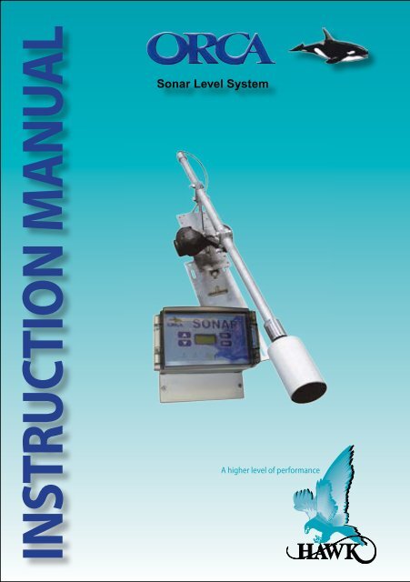
INSTRUCTION MANUALSonar Level SystemA higher level of performance
Sonar Level SystemMANUALRev 1.55, Nov 2012INTRODUCTIONCONTENTSPROPRIETARY NOTICEThe information contained in this publicationis derived in part from proprietary and patentdata. This information has been prepared forthe express purpose of assisting operating andmaintenance personnel in the efficient use ofthe instrument described herein. Publication ofthis information does not convey any rights touse or reproduce it, or to use for any purposeother than in connection with the installation,operation and maintenance of the equipmentdescribed herein.WARNING!This instrument contains electronic componentsthat are susceptible to damage by staticelectricity. Proper *handling procedures mustbe observed during the removal, installation, orhandling or internal circuit boards or devices.* Handling Procedure:1. Power to unit must be removed.2. Personnel must be grounded, via wrist strapor other safe, suitable means, before anyprinted circuit board or other internal devicesis installed, removed or adjusted.3. Printed circuit boards must be transportedin a conductive bag or other conductivecontainer. Boards must not be removed fromprotective enclosure until the immediate timeof installation. Removed boards must beplaced immediately in a protective containerfor transport, storage, or return to factory.Comments:This instrument is not unique in its contentof ESD (electrostatic discharge) sensitivecomponents. Most modern electronic designscontain components that utilize metal oxidetechnology (NMOS, CMOS, etc.). Experiencehas proven that even small amounts of staticelectricity can damage or destroy these devices.Damaged components, even though they appearto function properly, exhibit early failure.PATENT PENDING2Warranty and LiabilityGeneral DescriptionPrinciple of Operation 3Specifications 4Typical Applications 5Typical Installation Requirements 6Installation Guide 7Choosing a Sonar Transducer 8Choosing a Sonar Cleaning System 13Dimensions 15Floating Sonar Assembly 18Impact Plate 21Actuator Cleaner 23Bracket Nozzle Assembly 24Sonar Transducer Scraper Option 25Wiring Diagrams 26Devicenet / Profibus 31Software Menu Description 35Entering Data 45Startup - Commissioning 47Communication 70Error Codes 72Troubleshooting 73Part Numbering 74Application References 84
Sonar Level SystemMANUALRev 1.55, Nov 2012WARRANTY AND LIABILITY<strong>Hawk</strong> specializes in ultrasonic, sonic andsonar level transmitters and have thousandsof installed instruments in critical applicationsaround the world.<strong>Hawk</strong> guarantees the ‘<strong>ORCA</strong>’ sonar range,when delivered, is free of material defects andundertakes to replace, repair any defective part,free of charge. <strong>Hawk</strong> will provide two levels ofwarranty period.A two year electronic warranty period extendsfrom this delivery date, an installed performancewarranty is available through our distributornetwork and the factory.<strong>Hawk</strong> warranty, solely covers, workmanship,material defects, only, unless specified in writingby the factory.The warranty does not cover, wearing parts,consumables, incorrect handling, incorrectinstallation, or using the instrument for anythingother than what it is intended to do.GENERAL DESCRIPTION• The <strong>ORCA</strong> Sonar Series offers a wide andcomprehensive range of advantages formeasuring interface levels, etc.• Large range of sonar frequencies, tooptimize the best response in the tank.• Largest range of industrial cleaningmechanisms, to insure continuousperformance.• Suitable for measuring rocks, powders,viscous and aggressive media.• Suitable for all sonar applications including:primary sedimentation, secondary/finalclarifiers, thickeners, CCD’s, sequentialbatch reactors.• Max range 60m.• Calibration by programming density (grams/liters).• Two independent outputs available2 x 4-20ma analogue.• Modbus comms standard• GSM module remote support capability forcalibration, commissioning or technical backup.PRINCIPLE OF OPERATIONThe <strong>ORCA</strong> Sonar Series transducer emits ahigh powered acoustic pulse, which is reflectedfrom the interface density selected.The reflected signal is processed usingspecially developed software algorithms, thateliminates lighter floating densities, stratifiedlayers, when measuring “RAS” or “BED” levels.It can be calibrated to measure lighter densitieslike “FLOC” or one of the outputs could beused for a “CLARITY” output, similar to abasic turbidity transmitter measuring solids insuspension.By choosing the correct sonar transducerfrequency, the <strong>ORCA</strong> sonar guarantees the bestoptimized performance off both light densityinterfaces and heavy density interfaces.3
Sonar Level SystemMANUALRev 1.55, Nov 2012SPECIFICATIONSSonar Frequency Selection• 150kHz, 300kHz, 450kHz, 700kHz,Operating Voltage• 90 - 260Vac 50/60Hz• 24Vdc (min 5A supply)(residual ripple no greater than 100mV)Power Consumption•
Sonar Level SystemMANUALRev 1.55, Nov 2012TYPICAL APPLICATIONSAreaWater Treatment PlantPrimary Sedimentation TankSludge Thickener TankCalcium Hydroxide ReactorSodium Hydroxide ReactorSewage Treatment PlantPrimary Sedimentation TankSecondary / Final ClarifierSludge Thickener Tank“DAF” TankSequential Batch Reactor (SBR)Industrial (food, paper etc.)Primary Sedimentation TankSecondary Clarifier TankThickener Tank“DAF” TankSequential Batch Reactor (SBR)Carbon ColumnMining/Mineral processingClarifier TankThickener TankCCD’s TankSettling PondsFunctionsFloc level / sludge blanket levelSludge bed level / clarity suspended solids / floc levelSand/pellet bed levelSand/pellet bed levelSludge blanket levelRAS blanket level / rag/pinfloc layer / clarity suspendedsolidsSludge bed level / clarity suspended solidsSludge bed level / floating sludge levelSettling bed level / RAS blanket levelSludge blanket levelRAS blanket level / clarity suspended solids / rag/pinfloclayerSludge bed level / clarity suspended solids / floc levelSludge bed level / floating sludge levelSettling blanket level / RAS bed levelCarbon bed levelBlanket level / clarity suspended solids / stratified floclayersSludge bed level / clarity suspended solids / stratifiedfloc layersSludge bed level / clarity suspended solids / stratifiedfloc layersSludge bed level5
Sonar Level SystemMANUALRev 1.55, Nov 2012TYPICAL INSTALLATIONS REQUIREMENTSPositioning the Sonar Transducer(1) The sonar transducer should beinstalled approximately half submergedwithin the liquid level. Where the liquidlevel varies (sbr) use a floating sonarversion. The surface face of the sonartransducer must be immersed under theliquid level at all times.(2) Circular Tanks - centre feed (fixedor moving bridge versions) positionthe sonar transducer 1/3 radius fromthe tank wall. This is to minimise thedisturbance to the sonar measuringpulses.(3) Rectangular Tanks - position thesonar transducer at least 700mmfrom the side wall. Never position thesonar transducer over chains, site thetransducer, to minimise disturbancefrom the incoming liquid.Impact PlatesLeave an extra 2 turns of cable where thetransducer connects to the actuator tominimise stress and wear on the cable.See below for proper placement of cabletie if cable tie is used. Do not over tighten,it may lead to excessive cable wear.INCORRECTCORRECT1/3 Radius Feeder6
Sonar Level SystemMANUALRev 1.55, Nov 2012INSTALLATION GUIDESonar Transmitter – MountingRequirementsSelect a suitable mounting position,preferably not in direct sunlight. ifnecessary utilize a sunshade.Observe the maximum and minimumtemperature limits (-20ºc, -4ºf to 70ºc,165ºf).Do not mount the sonar transmitter nearhigh sources of EMF, such as motorstarters, variable speed drives or 3 phasecables. Avoid mounting in high vibrationareas, or use rubber absorption mounts.Be careful when removing the cable andcompression glands.Sonar Transducer – MountingRequirementsThe transducer should be half submergedin the liquid and the transducer face mustalways be submerged.DO NOT SUBMERGE THE ENTIRETRANSDUCERSUBMERSION:MININUM 50MMMAXIMUM 50%OF TRANSDUCERImpact PlatesLeave an extra 2 turns of cable where thetransducer connects to the actuator tominimise stress and wear on the cable.Round Tanks – Centre FeedwellMount the sonar transducer and cleaningmechanism, approximately one third radiusfrom the outside tank wall. This is thesame whether it is a moving or fixed bridgeinstallation.Do not mount near high infeed turbulence.Choose a site installation where the infeedis least disturbed.Rectangular Tanks – End FeedMount the sonar transducer and cleaningmechanism away from high infeedturbulence. A clearance of 700mm fromthe side wall.Do not mount directly over scraper, chainmechanisms. Choose a site installationwhere the infeed is least disturbed.Floating Sonar – SBRMount the floating sonar transducerand cleaning mechanism as close aspracticable to the launders.Mount at least 1.00 metres from side walls.make sure alignment guides are installedon the mounting bracket for decanterranges above 500mm.7
Sonar Level SystemMANUALRev 1.55, Nov 2012CHOOSING A SONAR CLEANING SYSTEMThe <strong>ORCA</strong> Series Sonar have developeda range of sonar transducer “sludge”cleaning options, that requires nomaintenance. they are industriallydesigned to minimise downtime.Types available:(a) Electric actuator(b) Pneumatic actuator(c) Rotary scum brush(d) Floating sonar - actuator(e) Impact plate with counterweight* Remember all sonar sensors need tohave some form of cleaning mechanism.Possible applications, where each type ofsludge cleaning option are used.(a) Electric Actuator(most common used)Applications:Fixed bridge, moving bridge circular orrectangular clarifier.Fixed bridge thickener or CCD.Mounted off a side wall of a tank, etc.Where not to use the Electric Actuator(1) Do not use the electric actuator cleanerversion, when surface scum collectorsor moving surface or sub-surfacemechanical parts can come in contactwith the sonar sensor and mountingpipe.(2) The electric actuator does not have anEx approval. Consult the factory.(b) Pneumatic ActuatorApplications:Fixed bridge, moving bridge circular orrectangular clarifier.Fixed bridge thickener or CCD.Mounted off side wall of a tank etc.Can be used in ex approvedapplications.Where not to use the pneumaticactuator.(1) Do not use the pneumatic actuatorscum cleaner version when surfacescum collectors or moving surfaceor sub surface mechanical parts cancome in contact with the sonar sensoror mounting pipe.(c) Rotary Scum BrushApplications:Generally used in applications wherethe clearance space is limited.Where not to use the Rotary ScumBrush(1) Do not use the rotary scum brush whensurface scum collectors or movingsurface or sub-surface mechanicalparts can come in contact with therotary brush, sonar sensor or mountingpipe.(2) Use Ex approved type in classifiedzone.(3) Do not use in heavy scale build-upapplications.13
Sonar Level SystemMANUALRev 1.55, Nov 2012CHOOSING A SONAR CLEANING SYSTEM(d) Floating Sonar - Actuator TypeApplications:SBR, IDAL, IDEA sequential batchreactors with varying water heights.Continuous measurement of bed levelin settlement ponds.Where not to use the Floating Sonar–Actuator Version(1) Do not use the floating sonar - actuatorcleaner version when surface scumcollectors or sub-surface mechanicalparts can come in contact with thesonar sensor float or mounting pipe.(e) Impact Plate with CounterweightApplications:Used where a surface scum connectorpasses in the path of the sonar sensorand mounting pipe.Circular and rectangular primary andsecondary clarifiers.Fixed bridge or moving bridgethickeners, picket fence thickeners orCCD’s.14
FESonar Level SystemMANUALRev 1.55, Nov 2012DIMENSIONSRAIL BASE PLATEDCBAREVISIONSTHIS DRAWING AND THE CONTENTS THEREOFFARE THE PROPRIETARY PROPERTY OF HAWKDWG NO.Angle Actuator Rear B150mm (5.9”)TOLERANCES(UNLESS NOTED)X = 0.1XX = 0.05XXX = 0.010ANGULAR = 1°TITLE:111.50mm (4.3”)19.25 (0.7”)2 x 8.5062mm (2.4”)100.75mm (3.9)59.25mm (2.3”)20 (0.7”)60mm (2.3”)FLOATING SONAR SENSORAPRVD:DATEMounting Bracket Base Plate4 BOL-M10x1.5x30 2CHECKED:DATE15-17 MAURVICTO3 ST-SS-AARHB-L 2DRAWN:DATEMT 07/09/20102 ST-SS-AASB-L 6HAWK MEACOMPANY:1 ST-SS-VBP-Bends 1ITEM NO. PART NUMBER QTY.MATERIAL:NOT TO SCALEALL D139.51.2.3.4.Welding finish: All connecting plates must be welded on all edgesWelding finish: All gaps between plates must be weld filledWelding radius: No less than 5mmRemove all sharp edges & burrsX29.25(1.1”)5mm(0.2”)41.50mm(1.6”)51mm (2.0”) 51mm (0.2”)5mm (0.2”)5mm (0.2”)Note:211.50mm (8.3”)127.50mm (5”)512.6mm (20.1”)156*m (6.1”)X650.0365.85mm(0.2”)570mm (22.4”)15570mm (22.4”)42.5 o = Decant Range3111.50mm (4.3”)831mm (32.7”)428.75(1.1”)148.0111.50 m (4.3”)19.25(0.7”)79.5OSIRT Transducer75mm (2.9”)1" BSP NippleOSIRT Fibreglass Transducer375mm (2.9”)25.019.25(0.7”)111.50mm (4.3”)135 mm (5.3”)1" BSP Nipple330mm (12.9”)R5mm (0.2”)111.520.0R4.25(0.1”)8.5250.0150.021 234 56 74.00(0.1”)
Sonar Level SystemMANUALRev 1.55, Nov 2012DIMENSIONSSONAR IMPACT PLATESONAR ACTUATOR CLEANER379.60mm (14.9”)156* mm (6.1”)423mm (16.6”)156*mm (6.1”)X570mm (22.4”)762.5mm (30”)X570mm (22.4”)762.5mm (30”)42.5 oα°X - Pipe length to suit* distance from safety rail or Bridgemay be variedNote: Advise physical dimension of surfacescum rake.IMPORTANTLeave an extra 2 turns of cable where thetransducer connects to the actuator to minimisestress and wear on the cable16
Sonar Level SystemMANUALRev 1.55, Nov 2012DIMENSIONS192mm (7.6”)106mm (4.2”)76.5 (3”)DIN Rail Mounting(clips included)Front Side Back192mm (7.6”)145mm (5.7”)10.5mm (0.4”)160mm (6.3”)106mm (4.2”)160mm (6.3”)142mm (5.6”)38mm (1.5”)83mm (3.3”)3 x 20mm (0.7”), 1x16mm (0.6”)Knock outs166mm (6.5”)61mm (2.4”) 8mm (0.3”)151mm (5.9”)166mm (6.5”)10mm (0.4”)17
Sonar Level SystemMANUALRev 1.55, Nov 2012FLOATING SONAR - ASSEMBLYPart No. Code DFloating Sonar Assembly18
Sonar Level SystemMANUALRev 1.55, Nov 2012FLOATING SONAR - ASSEMBLYPart No. Code DFloating Sonar AssemblyWater LevelUltrasonicTransducerMountingBracketMovingTargetCleaningActuatorSonarTransducer19
Sonar Level SystemMANUALRev 1.55, Nov 2012FLOATING SONAR - PARTSPart No. Code DWater Level TargetSliding PipePipe GuideSonar TransmitterWater Level TransmitterMounting BracketPipe GuideElectro-ActuatorSonar CleaningFloat withSonar Sensor20
Sonar Level SystemMANUALRev 1.55, Nov 2012IMPACT PLATE - DIMENSIONSPart No. Code E379.60320156*X570762.5Bracket 316SSHole Dia. 8.5mm111.520.041.559.25570.0530.75X – Pipe length to suit* distance from safetyrail or Bridgemay be varied111.58.5150.0Rail Base PlateIMPORTANTLeave an extra 2 turns ofcable where the transducerconnects to the actuator tominimise stress and wear onthe cable21
Sonar Level SystemMANUALRev 1.55, Nov 2012IMPACT PLATE - ASSEMBLYPart No. Code EIMPORTANTLeave an extra 2 turns of cable where the transducer connects to the actuator tominimise stress and wear on the cable22
Sonar Level SystemMANUALRev 1.55, Nov 2012ACTUATOR CLEANER - DIMENSIONSPart No. Code A423156*320X570762.5Bracket 316SSHole Dia. 8.5mm111.520.041.559.25570.0530.75X – Pipe length to suit* distance from safetyrail or Bridgemay be varied111.58.5150.0Rail Base Plate23
Sonar Level SystemMANUALRev 1.55, Nov 2012SONAR BRACKET NOZZLE - ASSEMBLYITEM NO. PART NUMBER QTY.1 Bracket SUBA 12 Custom 10inch Flange thin (5mm) 13 Rubber Slide 24 Custom 10inch Flange 15 Rubber Bellow Seal 11523424
xSonar Level SystemMANUALRev 1.55, Nov 2012SONAR TRANSDUCER SCRAPER OPTIONThis automated scraper system is used for applicationswhere suspended solids need to be mechanicallyremoved from the transducer face during eachcleaning sequence water sprays can be includedwith this option.Part Number: OSIRSC-ZSyUHMWScraperSonar TransducerMounting BracketSonar ScumCleaner ActuatorScraper ActuatorScraper MovementUHMWScraper25
Sonar Level SystemMANUALRev 1.55, Nov 2012WIRING DIAGRAM<strong>ORCA</strong> 234 Remote Transmitter with ActuatorSONAR 234 REMOTE TRANSMITTERRELAY 1 RELAY 2 RELAY 3 ACTUATORNCCOMNONCCOMNONCCOMNOBLKBLUBRNGRNYELSHLDANALOG2+-4-20mAANALOG1 TRANSDUCER COMMS DC-IN AC-INIs4-20mA- -REDBLKBLUWHTTest+BA+NL112-30VDC 90-265 VACTransducer CableBOTTOM TOPTRANSDUCER26
Sonar Level SystemMANUALRev 1.55, Nov 2012WIRING DIAGRAM<strong>ORCA</strong> 234 Remote Transmitter with Actuator & Junction BoxSONAR 234 REMOTE TRANSMITTERRELAY 1 RELAY 2 RELAY 3 ACTUATORActuatorNCCOMNONCCOMNONCCOMNOBLKBLUBRNGRNYELSHLDANALOG2+-4-20mAANALOG1 TRANSDUCER COMMS DC-IN AC-INIs4-20mA+- -REDBLKBLUWHTTestBA+NL112-30VDC 90-265 VACBOTTOM TOPTransducer CablePot CableMotor CableJunctionBoxBelden 3084A cableRefer to Graph 1 for cable selectionTRANSDUCER27
Sonar Level SystemMANUALRev 1.55, Nov 2012GRAPH 1: ACTUATOR CABLE SPECFilename: ActuatorCable3.xls Revised 6/12/2006 CTPNote 1: Calculations are based on …4.0 Amps max actuator current, and4.0 Volts drop across max cable length (2 wires).Note 2: Maximum terminal capacity is 1.5mm, which limits 16AWG cable to 35m.Note 3: For long cable runs, use 16 AWG to local junction box, then extend using 10-14 AWG.Note 4: Also required: 3-wire cable for feedback potentiometer, 0.5mm - 1.0mm.Gauge Nom OD Resist. Resist. Loss Max Res. Max DistAWG mm Ohm/1000ft Ohm/m V/m Ohm m10 2.920 1.08 0.0035 0.028 1.00 141.112 2.440 1.71 0.0056 0.045 1.00 89.114 1.930 2.73 0.0090 0.072 1.00 55.816 1.520 4.35 0.0143 0.114 1.00 35.018 1.220 6.92 0.0227 0.182 1.00 22.020 0.965 10.90 0.0358 0.286 1.00 14.0160.0Actuator Motor Cable GuideMax Distance (m)140.0120.0100.080.060.040.020.00.010 12 14 16 18 20Wire Gauge (AWG)28
Sonar Level SystemMANUALRev 1.55, Nov 2012WIRING DIAGRAMAnalog Output 1Terminal Connections for AC Supply – Model dependanta) Modulating from User’s External DC Supply (RL to Pos.)NOTE1*: RL Max = 750Ωif user DC Supply 24V90 - 260VAC Supply{User DC Supply+–+PLCDCSIND–RL Max 750Ω4-20mAUseshieldedcableL1N–+IsDC Supply4-20mATerminalConnectionb) Modulating from User’s External DC Supply (RL to Neg.)NOTE1*90 - 260VAC Supply{User DC Supplyc) 4 Wire AC – Driving from Internal Isolated Supply (Is)90 - 260VAC Supply{NOTE2*:Isolated current+output can be madecommon with externalPLCDC Supply Positive orDCSINDNegative if required.(e.g. RL – connected to GND) –+–+PLCDCSIND–RL Max 750Ω4-20mARL Max 400Ω4-20mAUseshieldedcableUseshieldedcableL1N–+IsL1N–+IsDC Supply4-20mADC Supply4-20mATerminalConnectionTerminalConnection29
Sonar Level SystemMANUALRev 1.55, Nov 2012WIRING DIAGRAMAnalog Output 1Terminal Connections for DC Supply – Model dependantd) 4 Wire DC– Driving from Internal Isolated Supply (Is+)NOTE2*UserDC Supply+–+PLCDCSIND–RL Max 400Ω4-20mAUse shielded cable+––+IsDC Supply4-20mATerminalConnectione) 3 Wire DC – Modulating from Common User Supply (RL to +DC)NOTE1*UserDC Supply+–+PLCDCSIND–RL Max 750Ω4-20mAUseshielded cable+––+DC Supply4-20mATerminalConnectionANALOG 2f) 3 Wire DC – Modulating from Common User Supply (RL to GND)NOTE1*UserDC Supply+–+PLCDCSIND–RL Max 750Ω4-20mAUseshieldedcable+––+DC Supply4-20mATerminalConnectionANALOG 230
Sonar Level SystemMANUALRev 1.55, Nov 2012WIRING DIAGRAMAnalog Output 2Terminal Connections for DC Supply – Model dependante) 3 Wire DC – Modulating from Common User Supply (RL to +DC)NOTE:Internal SMARTcard configuredfor 3, 4 wire.NOTE:RL Max = 750Ωif user DC Supply 24VUserDC Supply+–+PLCDCSIND–RL Max 400Ω4-20mAUseshielded cable+DCGND–+DC Supply4-20mATerminalConnectionANALOG 2f) 3 Wire DC – Modulating from Common User Supply (RL to GND)NOTE:Internal SMARTcard configuredfor 3, 4 wire.NOTE:RL Max = 750Ωif user DC Supply 24VUserDC Supply+–+PLCDCSIND–RL Max 400Ω4-20mAUseshieldedcable+DCGND–+DC Supply4-20mATerminalConnectionANALOG 231
Sonar Level SystemMANUALRev 1.55, Nov 2012DEVICENETDEVICENETMASTERSULTAN 234SULTAN 234 SULTAN 234EXTTERM5. V+4. CAN_H3. SHEILD2. CAN_L1. V-32
Sonar Level SystemMANUALRev 1.55, Nov 2012DEVICENETSet the BaudRate and theDeviceNet Address in SultanFactory defaults of baudrate and FBusAddsare 125kbps and 63 in a Sultan unit withDeviceNet CommType. To modify thesevalues follow the instructions below.1. Go to the Output Adjustment menu2. Use the Up and Down push buttons toreach the CommType parameter3. Make sure that the CommTyle is set toDeviceNet4. Press the CAL button twice5. DeviceID will be displayed6. Use the Down push button to reach theBaudRate parameter7. The default value for the BaudRate is125kpbs. Press CAL button and use the Upand Down push buttons to modify this value8. Press CAL button when finished9. Use the Down push button to reachthe FBusAdds. The default value of theFieldBus Address is 63. Press CAL buttonand use the Up and Down push buttons tomodify this value10. Press CAL button again when finishedOutput DataProfibus/Devicenet now transmit 18 bytes/9 words, description of the words is as follows (For firmwareversion 5.54 and above)1. Displayed Distance (Space Distance is the Primary Variable)2. Percentage (Percent of Range)3. Hi Level (Upper Range)4. Low Level (Lower Range)5. Status FlagsFailed ~~~~~~ Search 0 Echo Cfm : 1 =True, 0 = FalseBit F Bit E Bit 3 Bit 1 Bit 0Bit0 = Echo was received inside the span.Bit1 = Echo is Confirmed.Bit3 = Searching is searching for an Echo.BitF = Unit has Failed to detect an Echo.6. Displayed Distance2 (Second Variable)*7. Percentage2 (Second Percent of Range)*8. Displayed Distance3 (Third Variable)+9. Percentage3 (Third Percent of Range)+* Used for <strong>ORCA</strong> Sonar and Differential output on a Sultan+Only used for <strong>ORCA</strong> Sonar Clarity output.Echo R : 1 =True, 0 = False33
Sonar Level SystemMANUALRev 1.55, Nov 2012PROFIBUSPROFIBUSMASTERSULTAN 234SULTAN 234 SULTAN 234EXTTERM5. B IN4. A IN3. SHEILD2. B OUT1. A OUT34
Sonar Level SystemMANUALRev 1.55, Nov 2012Set the ProfiBus Address in SultanFactory defaults of FBusAdds is 126 in a Sultanunit with ProfiBus CommType. To modify thisvalue follow the instruction below:1. Go to the output Adjustment menu.2. Use the Up and Down push buttons to reachthe CommType parameter.3. Make sure that the CommType is set toProfiBus4. Press the CAL button twice.5. DeviceID will be displayed6. Use the Down push button to reach the BaudRateparameter.7. The value for the BaudRate is selected automaticallyand can not be modified.8. Use the Down push button to reach theFBusAdds. The default value of the FieldBusAddress is 126. Press CAL button and use theUp and Down push buttons to modify this value.9. Press CAL button again when finish.Output DataProfibus/Devicenet now transmit 18 bytes/9 words, description of the words is as follows (For firmwareversion 5.54 and above)1. Displayed Distance (Space Distance is the Primary Variable)2. Percentage (Percent of Range)3. Hi Level (Upper Range)4. Low Level (Lower Range)5. Status FlagsFailed ~~~~~~ Search 0 Echo Cfm : 1 =True, 0 = FalseBit F Bit E Bit 3 Bit 1 Bit 0Bit0 = Echo was received inside the span.Bit1 = Echo is Confirmed.Bit3 = Searching is searching for an Echo.BitF = Unit has Failed to detect an Echo.6. Displayed Distance2 (Second Variable)*7. Percentage2 (Second Percent of Range)*8. Displayed Distance3 (Third Variable)+9. Percentage3 (Third Percent of Range)+* Used for <strong>ORCA</strong> Sonar and Differential output on a Sultan+Only used for <strong>ORCA</strong> Sonar Clarity output.Echo R : 1 =True, 0 = False35
Sonar Level SystemMANUALRev 1.55, Nov 2012SOFTWARE MENU DESCRIPTIONENTERING DATAAll software adjustments are achieved via the four PUSH BUTTONS on the front panel.In Run Mode(A) Press and hold - interupts normal operations and allowsaccess to software menu headings.In Calibrate Mode(B) Momentary press - saves selected value.Press and hold - scrolls through set-up menus andparameters.In Run Mode(A) Displays operating diagnostics on display LCD.In Calibrate Mode(B) Increases display value.(C) Scrolls through software parameters.In Run Mode(A) Displays operating diagnostics on display LCD.In Calibrate Mode(B) Decreases display value.(C) Scrolls through software parameters.In Calibrate Mode(A) Press when all calibrations are complete.(B) Stores all parameters, returns the <strong>ORCA</strong> Sonar tonormal operating run mode.36
Sonar Level SystemMANUALRev 1.55, Nov 2012SOFTWARE MENU DESCRIPTIONMenu Headings ParametersQUICKSETTX SETUPOUTPUT ADUNITAPP TYPEAPP TYPE 2FAILSAFEDISP MODEI: SEN ADDOFFSETLOCK CODEGAINGAIN STEPDIST STEPTHRESHOLDBLANKINGEMPT DISTTEMP TRIMDIST TRIMVELOCITYE WIDTH 1GAIN 2THRESHOLD 2E WIDTH 2FLOCKFILL DAMPEMPTY DAMP4mA ADJ20mA ADJANALOG20mA ADJ 220mA ADJ 2SIMULATECOMMUNICATIONS TYPE - MODPUSOMM TYPERLY MOD 1RLY MOD 2RLY MOD 3CLEANING37
Sonar Level SystemMANUALRev 1.55, Nov 2012SOFTWARE MENU DESCRIPTIONQUICKSETUnits: Selectable metres, centimetres, feet, inches.App Type (application type): Selectable,RAS: Return activated sludge blanket levelBed: Bed level, thickener, primary sedimentationFloc: Floc level, floc/rag levelAPP Type 2OFFBEDRASFLOCCLARITYFAIL SAFE20mA, 4mA, Lst Knw, 20.20mA, 3.80A, 3.50mAFAIL TIME3.0min - 0.0minDISP MODELevel% LevelSPACEI: SEN ADD1 to 25Continued next pageOFFSET0.0cm500.0cm38
Sonar Level SystemMANUALRev 1.55, Nov 2012SOFTWARE MENU DESCRIPTIONContinued from previous pageDensity (choose density)0.1 gram to 10 gram/litreCalibrate (fine adjust density)0.0% to 26.7%Lo Level0% or 4ma position0 - 60 metresHi Level100% or 20ma position0 - 60 metresFill Rate0.1m to >20m per hour fill rateEmpty Rate0.1m to >20m per hour pump out rateContinued next page39
Sonar Level SystemMANUALRev 1.55, Nov 2012SOFTWARE MENU DESCRIPTIONContinued from previous pageFailsafe ModeOptions: 3.50ma, 3.80ma, 20.20ma, last known,4.0ma, 20.00maFail Time0.0 minutes to >20.0 minutesDisplay ModeOptions: space: (distance from transducer tointerface)Level: (distance from bottom of tank to depth ofinterface)% Level: percentage of vessel full.OffsetAllows the user to move the start pointof the measurement0.0m to 5.0mLock CodeAllows the user to enter a security code0 to 65,00040
Sonar Level SystemMANUALRev 1.55, Nov 2012SOFTWARE MENU DESCRIPTIONTX SETUPGain:Sensitivity range of sonar transducer.Factory set for applications.Range: 0.0% to 95.0%Gain Step:Fixed gain level near sonar transducer face.Factory set for each transducer frequency.Range: 0.0% to 80%Distance Step:The distance out from the transducer face where thefixed low gain (gain step) applies. Generally used to reducea mechanical mounting reflection near the transducerRange: 0.350mm to >10.0mFactory set for each transducer frequency.Threshold:Factory set for selected applications. the sizes of the signalin volts, that instrument will accept as validated.Check with your distributor or the factory before changing.Range: 0.00v to 2.49vNote:To increase the range capabilityof the transmitter, increasethe empty distance to a greaterdistance than required for theapplication.Blanking:Distance from transducer face, where the software isprevented from measuring.Range: 0.000mm to >10.0mEmpty Distance:A distance longer than low level, the software preventsmeasurements from past this distance.Note: Conical shaped vessels need longer emptydistances.Range: 0.600 to 65.0mContinued next page41
Sonar Level SystemMANUALRev 1.55, Nov 2012SOFTWARE MENU DESCRIPTIONContinued from previous pageTemperature Trim:The sonar transducer has an inbuilt temperaturecompensator. This parameter allows the inbuilttemperatures sensor to be calibrated.Range: -50.0ºc to 160.0ºc. Factory calibrated.Distance Trim:Allows for fine calibration of the measuring distance.Only when required. Factory calibrated.Velocity:Allows for a change in the speed of sound.Factory calibrated consult your distributor or factory.E Width 1:Factory calibrated consult your distributor or factory.Application 2 #(only used with Dual Analogue Orca Transmitter)Gain 2:Sensitivity range of sonar transducer factory set forapplications.Range: 0.0% to 95.0%Threshold 2:Factory set for selected applications the size of the signalin volts, that the instrument will accept as validated.Check with your distributor or factory before changing.Range: 0.00v to 2.49vE Width 2:Factory calibrated.Consult your distributor or factory.FLOC MARGContinued next page42
Sonar Level SystemMANUALRev 1.55, Nov 2012SOFTWARE MENU DESCRIPTIONOUTPUT ADJUSTFill Damping (tank filling):The number of pulses that the analogue output isaveraged over.eg: 60 = 60 pulses = 1 minute. Analogue outputchanges, by the average change in this time period.Empty Damping (tank emptying):The number of pulses that the analogue output isaveraged over.eg: 120 = 120 pulses = 2 minutes. Analogue outputchanges by the average change in this time period.4mA Adjust:Trim 4mA Output20mA Adjust:Trim 20mA OutputAnalog4ma - 20maInvert Output20ma - 4maSimulate:Drive the output and display using up/down push buttons.4mA Adjust 220mA Adj 2Comm Type:Modbus (factory default)Options: Hart, Profibus.Continued next page43
Sonar Level SystemMANUALRev 1.55, Nov 2012SOFTWARE MENU DESCRIPTIONContinued from previous pageRelay Mode 1:EN EnergiseOptions: FS FailsafeOff Out of serviceDEN De-energisedRelay L1 (1) turn on: 0.800mL2 (1) turn off: 0.900mRelay setpoints 0.00m to 65.0mRelay Mode 2:EN EnergiseOptions: FS FailsafeOff Out of serviceDEN De-energisedRelay L1 (2) turn on: 1.000mL2 (2) turn off: 1.100mRelay Mode 3:EN EnergisedOptions: FS FailsafeOff Out of serviceDEN De-energisedRelay L1 (3): 1.200mL2 (3): 1.300mCleaning:OffOptions: ActuatorActuator max. position 80.4mm (max. movement of actuator)Actuator min. position 53.6mm (return position of actuator)Range: Factory adjustedContact distributor or factoryNo maintenance requirement.Max 5yrs operation, 1 operation/hrCycle:Actuator operation time (cycle)Suggested: 120 min between cleansRange: 5 minutes to >10 hrs44
Sonar Level SystemMANUALRev 1.55, Nov 2012ENTERING DATASOFTWARE TREETo CalibratePressPressPressPressRAS0.850mCALUNLOCK0CALQUICKSETTX SETUPOUTPUT ADRun DisplayExample application – RAS Blanket.Depth of RAS Blanket – 0.850mOnstart up there is nosecurity code protection.QuicksetMenu covers all basic parametersplus application choises.Transducer SetupUsed only in very specialapplications, consult distributor orfactory.Output AdjustChange output functions.PressRUNPressBack to normalRun Mode45
Sonar Level SystemMANUALRev 1.55, Nov 2012ENTERING DATADIAGNOSTIC DISPLAYSThe diagnostic displays appear on the top line of the display, after pressing thepush button when the sonar transmitter is in the operations mode.The diagnostics provide the user with valuable performance feedback on how thesonar is performing, whilst in operation mode.Example:PressPressPressRAS0.850mE: 3.2200.850mS: 2.05v0.850mRun Mode DisplayRAS (application)RAS Bed LevelE: 3.220 (in metres)Instant echo distance per each pulsebased on application set-up parameters.<strong>Measurement</strong> from sonar transducer.RAS Bed LevelS: 2.05vThis is the amplitude of the signalreturn in volts, from the interface.RAS Bed LevelPressG: 42.0%0.850mG: Gain sensitivity at the distance thesignal is detected.RAS Bed LevelPressR: 1.1%0.850mR: The amount of recover gain if thesignal drops below thresholddetection level.RAS Bed LevelContinued next page46
Sonar Level SystemMANUALRev 1.55, Nov 2012ENTERING DATAContinued from previous pagePressPressPressN: 1.9%0.850mT: 24.2C0.850mWI: 3.0700.850mN: Background noise levelRAS Bed LevelT: Liquid temperatures at sonar transducerRAS Bed LevelWI: start of window tracking position,in metres from sonar transducerRAS Bed LevelPressPressWI: 4.2700.850mNORMAL0.850mRAS0.850mWI: end of window tracking positionRAS Bed LevelNORMAL = Normal operation if echoreceived above thresholdRECOVER = Echo below thresholdincreasing gain.FAILED = No echo received. possiblefailed transducer or cable problem.RAS Bed LevelReturn to application displayRAS Bed Level47
Sonar Level SystemMANUALRev 1.55, Nov 2012START UP - COMMISSIONINGAfter making sure that the sonar isinstalled correctly, turn the power on tocalibrate and commission the instrument.The <strong>ORCA</strong> Sonar has been designed towork on a number of different applications,that require variations to the set-up. Tosimplify the set-up we have developed an‘Application Menu’.The ‘Application Menu’ covers the mostcommonly seen sonar applications. The<strong>ORCA</strong> sonar can be calibrated to handlemany other sonar interface applications upto a range of 60 metres.Please see the following applicationexamples.Analogue Output No. 1 (output 1)(1) RAS (return activated sludge)blanket(2) Floc (floc/rag layer)(floc polyelectrolyte blanket)(3) Bed level (primary sedimentationtank) (thickener/ccd’s)Analogue Output No. 2 (output 2)(4) RAS (return activated sludge)blanket(5) Floc (floc/rag layer)(floc polyelectrolyte blanket)(6) Bed level (primary sedimentationtank) (thickener/ccd’s)(7) Clarity (suspended solidsmonitoring)If your application for the sonar does notappear in the list, contact your distributoror the factory.Note: Some ‘RAS Blanket’, ‘Bed Level’and ‘Floc Interface’ applications,experience high fluctuation, causedby hydraulic imbalance inflowcharacteristics. It can vary inalternative tanks at the same site.To verify the sonar is measuringthe correct density interface, use aportable turbidity analyzer or a sludgejudge clear pipe.Using the portable turbidity analyzerand holding it at a fixed depth, willindicate how much the interface isfluctuating in height.Remember, the RAS Blanket, or Bedof a thickener is never flat.The heavier the density, the morestable the measurement.Consult your distributor or factory formore support.48
Sonar Level SystemMANUALRev 1.55, Nov 2012START UP - COMMISSIONINGAPPLICATION 1:RAS Blanket (Secondary/Final Clarifier)(a) (Sewage treatment and waste water treatment plants)(Select application: RAS select density level to track)(Programming)Secondary Clarifier RAS Floc Calibrationnit is Orca Sonar 234 Wire Standard Range.Quick StartLow Level(m):Tx SetupTrackingGain(%): 10.0 Recover First(%): 0.0Hi Level(m):Recover Max(%):30.0Application:Rate of Fill:Damp Fill:Rate of Empty:Damp Empty:Fail Safe:Fail Safe Time:RAS Recover Inc.(%): 0.51.0 Threshold(V): 0.60 Window(m): 1.008180 Win Fwd(m): 0.0031.0 EmptyDist(m):Win Back(m): 0.0031804.00mA180Lock Code: 0 Threshold 2: 1.00Disp Mode:Space Echo Width(m): 0.200 Echo Width(m): 0.200Low Level 2(m):Echo Width 2(m):0.300Hi Level 2(m): Gain 2(%):14.9Application 2:Density:Density 2:Cablbrat(%):SmplRate(min):Damping 2:FLOC FlocMargin(m): 0.4003.0-6.0g SlopeMin(m): 0.1001.2-3.0g GainStartMax: 12.01.91.018049
APPLICATION 1:Sonar Level SystemRAS Blanket (Secondary/Final Clarifier)(a) (Sewage treatment and waste water treatment plants)(Select application: RAS select density level to track)(Programming)START UP - COMMISSIONINGExample SetupPressCALMANUALRev 1.55, Nov 2012UNLOCK0PressCALQUICKSETUnits ofmeasurementPressPressPress twicePressCALUNITMETRESAPP TYPERASCALDENSITY1.2 - 3.0 G/LCALChoice: metrescentimetresfeetinchesPressApplication Type: RASBed ChangeFlocDensity range: 0.1 to 10.0 g/lPressDensity Edit, AdjustPressPressContinued next page50
Sonar Level SystemMANUALRev 1.55, Nov 2012START UP - COMMISSIONINGContinuedfrom previouspageCalibrate parameterallows fine adjustmentof the density trackingposition.(Example)Display readsSize of return echoDisplay resumesPressPressPressPressPressDENSITY3.0 - 6.0 G/LCALCALIBRATE9.9%CALCALIBRATE8.0%CALCalibrate editCALIBRATE1.5VCALIBRATE8.0%Typical RAS Density2.5 G/L to 4.0 G/LFine adjust calibrate of density setting.Range: 0.0% to 26.7%Reduce number to 8.0%(Decrease number heavier density)(Increase number lighter density)ThenCALIBRATE3.50MDistance where interfacewas detected.Display readsPressCALIBRATE8.0%CALCALIBRATE2.2VThenContinued next pageCorrect RAS blanket levelCALIBRATE4.00M51
Sonar Level SystemMANUALRev 1.55, Nov 2012START UP - COMMISSIONINGContinued fromprevious pagePressRUNLow Level: 4mA (0%)High Level: 20ma (100%)Adjust for maximumspeed that the interfacecan move.Adjust for maximumspeed that the interfacecan move.PressPressPressPressPressPressLOW LEVEL10.00mCALCALHIGH LEVEL0.50mFILL RATE1.0m/HCALEMPTY RATE1.0m/HPressPressLOW LEVEL6.50mCALCALCALCALCALLow Level EditPressPressPressHi Level Edit Range: 0.0 to 59.9mEdit Fill RateEdit Empty RatePressMonitors Tank FillingPressRange: 100mm to 60.0mRange: 0.1m/H to >10.0m/HPressMonitors Tank EmptyingPressRange: 0.1m/H to >10.0m/HPressContinued next page52
Sonar Level SystemMANUALRev 1.55, Nov 2012START UP - COMMISSIONINGContinued from previous pageChoose a failsafe condition.The time, after a fault hasoccurred before failedoutput condition.Display reading distance,bottom of tank up, or topof tank down.Allows start position levelto be altered.PressPressPressPressFAILSAFE20.00mACALFAIL TIME3.0minCALDISPLAY MODELEVELPressPressPressPressCALCALCALCALOFFSET0.000mCALCALPressEditPressEditPressEditPress20.00ma4.00maChoices: last known20.20maPress 3.80ma3.50maRange: 0.0 min to >10.0 minPressChoice: SpaceLevelPress % LevelEdit Range: 0.000m to 5.0mPressSecurity CodePressLOCK CODE0CALZero code, no security.PressEdit Range: 0 to 65,000PressRUNPressPress and hold until transmitter starts measuring.53
Sonar Level SystemMANUALRev 1.55, Nov 2012START UP - COMMISSIONINGAPPLICATION 2:Flock/RAG Layer(Water treatment plants - Floc Blanket)(Sewage treatment and waste water treatment plants - Secondary/Final Clarifiers - Floc/RAG Layer)Clarifier Floc Level Calibration54
APPLICATION 2:Flock/RAG LayerSonar Level SystemSTART UP - COMMISSIONING(Water treatment plants - Floc Blanket)(Sewage treatment and waste water treatment plants - Secondary/Final Clarifiers - Floc/RAG Layer)MANUALRev 1.55, Nov 2012Example SetupPressCALPressUNLOCK0CALQUICKSETUnits ofmeasurementPressPressCALUNITMETRESPressPressAPP TYPERASCALAPP TYPEFLOCCALApplication Type: RASBedPressFlocEditPressContinued next page55
Sonar Level SystemMANUALRev 1.55, Nov 2012START UP - COMMISSIONINGContinued from previous pageAllows fineadjustment of thedensity trackingposition.Display readsSize ofreturn echoDisplay resumes(Example)PressPressPressPressPressDENSITY1.2 - 3.0 G/LCALDENSITY0.1 - 0.6 G/LCALCALIBRATE8.0%CALCALIBRATE0.5VCALIBRATE8.0%CALIBRATE14.0%CALDensity Range: 0.1 to 10.0G/LPressDensity EditThenPressFine adjust calibrate of density setting.Range: 0.0% to 26.7%CALIBRATE2.60mDistance where interfacewas detected.Continued next page56
Sonar Level SystemMANUALRev 1.55, Nov 2012START UP - COMMISSIONINGContinued from previous pageDisplay readsIncreased echo sizeon top of Floc BlanketDisplay resumesPressPressCALIBRATE2.2VCALCALIBRATE14.0%RUNThenCALIBRATE2.00MDistance where Flocinterface is detected.Low Level: 4mA (0%)High Level: 20ma (100%)Adjust for maximumspeed that the interfacecan move.PressPressPressPressPressPressLOW LEVEL10.00mCALLOW LEVEL6.50mCALHIGH LEVEL0.50mCALCALFILL RATE1.0m/HCALCALLow Level EditPressPressPressHi Level Edit Range: 0.0 to 59.9mEdit Fill RatePressMonitors Tank FillingPressRange: 100mm to 60.0mRange: 0.1m/H to >10.0m/HPressContinued next page57
Sonar Level SystemMANUALRev 1.55, Nov 2012START UP - COMMISSIONINGContinued from previous pageAdjust for maximumspeed that the interfacecan move.Choose a failsafecondition.The time, after a fault hasoccurred before failedoutput condition.Display reading distance,bottom of tank up, ortop of tank down.Allows start positionlevel to be altered.EMPTY RATE1.0m/HPressPressPressPressPressPressFAILSAFE20.00mAFAIL TIME3.0minEdit Empty RateDISPLAY MODELEVELPressPressPressPressCALCALCALCALCALCALCALCALOFFSET0.000mCALMonitors Tank EmptyingPressPressPressPressCALContinued next pagePressPressPressRange: 0.1m/H to >10.0m/HPress20.00mA4.00mAEdit Choices: Last Known20.20mAPress 3.80mA3.50mAEditEditRange: 0.0 min to >10.0 minChoice: SpaceLevelPress % LevelEdit Range: 0.000m to 5.0m58
Sonar Level SystemMANUALRev 1.55, Nov 2012START UP - COMMISSIONINGContinued from previous pageSecurity CodePressLOCK CODE0CALZero code, no security.PressEdit Range: 0 to 65,000PressRUNPressPress and hold until transmitter starts measuring.Note:Some ‘RAS Blanket’, ‘Bed Level’ and ‘Floc Interface’ applications, experience highfluctuation, caused by hydraulic imbalance inflow characteristics. It can vary in alternativetanks at the same site.To verify the sonar is measuring the correct density interface, use a portable turbidityanalyzer or a sludge judge clear pipe.Using the portable turbidity analyzer and holding it at a fixed depth, will indicate how muchthe interface is fluctuating in height.Remember, the RAS Blanket, or Bed of a thickener is never flat.The heavier the density, the more stable the measurement.Consult your distributor or factory for more support.59
Sonar Level SystemMANUALRev 1.55, Nov 2012START UP - COMMISSIONINGAPPLICATION 3:Bed Level (thickener) *Sonar Transducer: 3 crystal and 7 crystal types(a) (Sewage treatment and waste water treatment plants - thickeners)(b) (Mining - thickeners, CCD’s)(c) (Food - thickeners, carbon columns)Thickener Bed Level Calibration60
APPLICATION 3:Sonar Level SystemBed Level (thickener)(a) (Sewage treatment and waste water treatment plants - thickeners)START UP - COMMISSIONING(b) (Mining - thickeners, CCD's)(c) (Food - thickeners, carson columns)MANUALRev 1.55, Nov 2012Example SetupPressCALMenu headingUNLOCK0PressCALQUICKSETPressCALUnits of measurementPressUNITMETRESChoice:MetresCentimetresFeetInchesPressPressAPP TYPERASCALAPP TYPEBEDCALPressEditApplication Type: RASBedFlocBed LevelPressContinued next page61
Sonar Level SystemMANUALRev 1.55, Nov 2012START UP - COMMISSIONINGContinued from previous pagePressPressDENSITY3.0 - 6.0 G/LCALDENSITY6.0 - 10 G/LCALDensity EditDensity Range: 0.1 to 10.0G/LPressPressAllows fine adjustmentof the density trackingposition.Display readsSize of return echoDisplay resumes(Example)PressPressPressCALIBRATE10.1%CALCALIBRATE1.0VCALIBRATE10.1%CALIBRATE8.0%CALFine adjust calibrate of density setting.Range: 0.0% to 26.7%ThenCALIBRATE3.50mDistance where interfacewas detected.(Needs to read lower)Continued next page62
Sonar Level SystemMANUALRev 1.55, Nov 2012START UP - COMMISSIONINGContinued from previous pageDisplay readsIncreasedreturn echo(good signal)Low Level: 4mA (0%)High Level: 20ma (100%)Adjust for maximumspeed that the interfacecan move.PressPressPressPressPressPressPressCALIBRATE2.0VRUNLOW LEVEL10.00mCALLOW LEVEL6.50mCALHIGH LEVEL0.50mCALCALFILL RATE1.0m/HCALCALLow Level EditThenPressCALIBRATE4.50mPressHi Level Edit Range: 0.0 to 59.9mEdit Fill RatePressPressMonitors Tank FillingPressNow distance where interfacebed level detected.Range: 100mm to 60.0mPressRange: 0.1m/H to >10.0m/HContinued next page63
Sonar Level SystemMANUALRev 1.55, Nov 2012START UP - COMMISSIONINGContinued from previous pageAdjust for maximumspeed that the interfacecan move.PressPressEMPTY RATE1.0m/HCALCALEdit Empty RateMonitors Tank EmptyingPressPressRange: 0.1m/H to >10.0m/HChoose a failsafecondition.The time, after a faulthas occurred beforefailed outputcondition.Display readingdistance, bottom oftank up, or top oftank down.Allows start positionlevel to be altered.PressPressPressPressFAILSAFE20.00mACALFAIL TIME3.0minCALDISPLAY MODELEVELPressPressPressPressCALCALCALCALOFFSET0.000mCALCALEditEditEditPressPressPressPressPressPressContinued next page20.00mA4.00mAChoices: Last Known20.20mAPress 3.80mA3.50mARange: 0.0 min to >10.0 minChoice: SpaceLevelPress % LevelEdit Range: 0.000m to 5.0m64
Sonar Level SystemMANUALRev 1.55, Nov 2012START UP - COMMISSIONINGContinued from previous pageSecurity CodePressLOCK CODE0CALZero code, no security.PressEdit Range: 0 to 65,000PressRUNPressPress and hold until transmitter starts measuring.Note:Some ‘RAS Blanket’, ‘Bed Level’ and ‘Floc Interface’ applications, experience highfluctuation, caused by hydraulic imbalance inflow characteristics. It can vary in alternativetanks at the same site.To verify the sonar is measuring the correct density interface, use a portable turbidityanalyzer or a sludge judge clear pipe.Using the portable turbidity analyzer and holding it at a fixed depth, will indicate how muchthe interface is fluctuating in height.Remember, the RAS Blanket, or Bed of a thickener is never flat.The heavier the density, the more stable the measurement.Consult your distributor or factory for more support.65
Sonar Level SystemMANUALRev 1.55, Nov 2012START UP - COMMISSIONINGAPPLICATION 4:Primary Sludge Blanket (Primary Sedimentation Tank)(a) (Sewage treatment plant and waste water treatment plans)(b) (Paper and industrial waste treatment plants)Primary Sedimentation Bed Level Calibration66
APPLICATION 4:Sonar Level SystemPrimary Sludge Blanket (Primary Sedimentation Tank)START UP - COMMISSIONING(a) (Sewage treatment plant and waste water treatment plans)(b) (Paper and industrial waste treatment plants)MANUALRev 1.55, Nov 2012Example SetupPressCALMenu headingUNLOCK0PressCALQUICKSETPressCALUnits ofmeasurementPressUNITMETRESMetresChoice: CentimetresFeetInchesPressPressAPP TYPERASCALAPP TYPEBEDCALPressEditApplication Type:Bed LevelRASBedFlocPressContinued next page67
Sonar Level SystemMANUALRev 1.55, Nov 2012START UP - COMMISSIONINGContinued from previous pagePressDENSITY3.0 - 6.0 G/LCALDensity Range: 0.1 to 10.0G/LAllows fine adjustmentof the density trackingposition.Size of return echo ofSludge BlanketDisplay resumesLow Level: 4mA (0%)PressPressPressPressCALIBRATE10.1%CALCALIBRATE2.0VCALIBRATE10.1%RUNLOW LEVEL10.00mCALLOW LEVEL6.50mCALLow Level EditFine adjust calibrate of density setting.Range: 0.0% to 26.7%ThenPressCALIBRATE4.20mDistance where Sludge Blanketwas detected.Use to decrease density.Use to increase density.Then pressCALto check.New bed level position.Range: 100mm to 60.0mPressContinued next page68
Sonar Level SystemMANUALRev 1.55, Nov 2012START UP - COMMISSIONINGContinued from previous pageHigh Level: 20ma (100%)PressHIGH LEVEL0.50mCALPressHi Level Edit Range 0.0 to 59.9mAdjust for maximumspeed that the interfacecan move.Adjust for maximumspeed that the interfacecan move.PressPressPressEMPTY RATE1.0m/HPressPressCALFILL RATE1.0m/HCALCALCALCALEdit Fill RateEdit Empty RatePressMonitors Tank FillingPressMonitors Tank EmptyingPressRange: 0.1m/H to >10.0m/HPressRange: 0.1m/H to >10.0m/HPressChoose a failsafecondition.The time, after a faulthas occurred beforefailed output condition.PressPressPressPressFAILSAFE20.00mACALCALFAIL TIME3.0minCALCALEditEditPressPressContinued next page20.00mA4.00mAChoices: Last Known20.20mAPress 3.80mA3.50mARange: 0.0 min to >10.0 minPress69
Sonar Level SystemMANUALRev 1.55, Nov 2012START UP - COMMISSIONINGContinued from previous pageDisplay reading distance,bottom of tank up,or top of tank down.Allows start positionlevel to be altered.Security CodeDISPLAY MODELEVELPressPressPressPressPressCALCALOFFSET0.000mCALCALLOCK CODE0CALEditPressPressChoice: SpaceLevelPress % LevelEdit Range: 0.000m to 5.0mPressZero code, no security.PressEdit Range: 0 to 65,000PressRUNPressPress and hold until transmitter starts measuring.Note:Some ‘RAS Blanket’, ‘Bed Level’ and ‘Floc Interface’ applications, experience highfluctuation, caused by hydraulic imbalance inflow characteristics. It can vary in alternativetanks at the same site.To verify the sonar is measuring the correct density interface, use a portable turbidityanalyzer or a sludge judge clear pipe.Using the portable turbidity analyzer and holding it at a fixed depth, will indicate how muchthe interface is fluctuating in height.Remember, the RAS Blanket, or Bed of a thickener is never flat.The heavier the density, the more stable the measurement.Consult your distributor or factory for more support.70
SULTAN 234SULTAN 234Sonar Level SystemMANUALRev 1.55, Nov 2012COMMUNICATION - MULTIDROP CONNECTIONGladiatorAdmittanceSwitchGladiatorAdmittanceSwitchGladiatorAdmittanceSwitchGladiatorAdmittanceSwitchSultan AcousticWave TransmitterSlurriesSultan AcousticWave TransmitterFloatation CellsGLadiatorMicrowaveLow LevelSultan Acoustic Wave TransmitterSilo, bin levels, coal, plastic powder,woodchip, sawdust, cement,clinker, iron ore, lime etc.GladiatorMicrowaveLow LevelGladiatorVibrationSwitchGladiatorConductivitySwitchSultan Smart TransducerFarm Tanks, Grain TerminalsGladiatorConductivitySwitchOrca Sonar InterfaceThickener, CCDSultan AcousticWave SwitchBlocked Chute DetectionOrca Sonar InterfaceClarifierGSM NetworkorCDMA NetworkSultan Master/Slave Positioning SystemSultan Acoustic Wave TransmitterStockpiles, Stackers,ReclaimersGSM or CDMA Network• Typically up to 31 transmitters or switches per string.• Maximum 250 transmitters or switches.• Using GSM/CDMA network, transmitters and switches can bemonitored, calibrated remotely.• Alarm status, diagnostics can be monitored.• Support from factory engineering for customer application problems.Laptop or PC Communicationsor PLC / DCS withMODBUS RTU PortGos<strong>Hawk</strong> Software forinventory monitoring on PC(Limited Modbus query rate for Switches only)71
Sonar Level SystemMANUALRev 1.55, Nov 2012COMMUNICATION - REMOTEGSM/CDMA Communication<strong>Hawk</strong>Link GSM/CDMA communicationdevice allows any authorized computer witha standard modem and Gos<strong>Hawk</strong> softwareto dial in and calibrate, test or check onthe performance of the connected <strong>Hawk</strong>product. The <strong>Hawk</strong>Link device can be wiredto the standard communication terminals ofthe <strong>Hawk</strong> products.ProtocolsGos<strong>Hawk</strong>HARTModbusProfibus DPProfibus PAFoundation FieldbusDeviceNetRemote technical support and completecommissioning of equipment in applicationsvia our GSM/CDMA module allows monitoringand adjustments of settings no matterwhat corner of the world.Remote connection worldwide!72
Sonar Level SystemMANUALRev 1.55, Nov 2012ERROR CODESERROR CODE 01 - 04Error 01: Amplifier can not talk totransducer.Error 02: Amplifier can talk to transducerbut transducer gives incorrect response.Error 03: ProfiBus or DeviceNet is selectedbut ProfiBus or DeviceNet module is notconnected or responding.Error 04: Amplifier is programmed withincorrect software.In general Error Code 01 indicates thereis NO communication and Error Code 02says there IS communication, but not ofsufficient quality to be read reliably.ERROR CODESError 01 InformationIf Error 01 exists, then the amplifier can notcommunicate with the transducer, so it isimpossible for it to display the address foryou (the display cycle for Error 01 does notshow any transducer information).To find the transducer address you mustconnect directly to the transducer wires,then you will need to use the ‘ID Search-Tx ID Search’ function of Gos<strong>Hawk</strong>II,or the Modscan program and Txfindutility. The BLUE and WHITE transducercommunication wires and a Groundconnection must be connected to yourPC via the RS485 converter. The PC thencommunicates directly with the transducer,not via the amplifier. The RED and BLACKtransducer wires must remain connectedto the amplifier terminals. These supplythe correct power to the transducer.The amplifier should be powered ON asnormal, then press CAL until the displaystops scrolling through the diagnosticmessages. Start Gos<strong>Hawk</strong>II and use the‘ID Search- Tx ID Search’ function. Thetransducer serial number will appear nextto the ID number to which it is currently set.The same thing will occur if you use theModscan program and Txfind utility.Record the ID number found, power off,and reconnect the transducer BLUE andWHITE wires to the amplifier terminals, andconnect the RS485 converter to the ‘A’ and‘B’ Modbus terminals as normal.Error 02 InformationError 02 indicates a communication datacorruption between AWA and Transducer.It can be a result of noise in data lines orone of data lines (“A” or “B”) being opencircuit.1. Make sure wiring is correct especiallylook to the screen (earth).2. If it still doesn’t work, you should thendisconnect the Transducer from AWAand check modbus ID’s of both AWAand Tx through Gos<strong>Hawk</strong>II “ID Search”.If the ID numbers don’t match, writedown Transducer ID number and thenconnect AWA to Gos<strong>Hawk</strong>II and changeit’s Modbus ID to recorded valuethrough “Info Screen” window.3. If the Transducer can’t communicatewith Gos<strong>Hawk</strong>II send it back to Factoryfor replacement.73
Sonar Level SystemMANUALRev 1.55, Nov 2012TROUBLESHOOTINGTesting the 4-20mA OUTPUT1. Disconnect all wire out of the 4-20mA.2. Connect the mA meters Red lead (+) of the 4-20mA IS terminal.3. Connect the Black lead (-) to the 4-20mA + terminal.4. Select the OUTPUT ADJ parameter5. Select 4mA Adj and press CAL.6. If you don’t see any mA output, go to step13.7. Use should now see 4mA on the multimeter.8. Adjust the 4mA by pressing up or down.Press enter to store and move to the next parameter.9. Press CAL to edit the 20mA.10. Use should now see 20mA on the multimeter.11. Adjust the 20mA by pressing up or down. Press enter to store and move.12. Current output is OK13. Test your current meter to confirm it works and the fuse is OK.14. Test the IS (Isolated voltage output). You will need a Volt meter.Set the meter to DC.15. Connect the Volt meter + to the IS terminal.16. Connect the Volt meter – to the 4-20mA – terminal.17. You should have a Voltage reading >14V DC.18. If you do not have this then check the Analogue SMART card is inserted correctly.Remove the card and insert it again.19. Make sure the card is in 3/4 wire mode.74
Sonar Level SystemMANUALRev 1.55, Nov 2012TROUBLESHOOTING<strong>ORCA</strong> 24 Volt DC Electric ActuatorTroubleshootingThe <strong>ORCA</strong> Sonar system is often used with anelectric linear actuator, powered and controlledby internal electronics in the standard amplifier.This section describes several tests which canbe made on the complete system, and on theindividual parts, to try to identify the cause of aproblem where a unit seems not to be operatingcorrectly.The <strong>ORCA</strong> amplifier and actuator componentsare highly reliable, so the first steps will be toverify that the mechanical assembly, wiring andbasic software settings are correct for 24VDCactuator cleaning operation.Mechanical Checks:-Ensure that the actuator, bracket, transducermounting pipe and hinged clamps are assembledas per the diagram on pages 48-55 of the<strong>ORCA</strong> manual.-Ensure that the pinch bolts which secure thehinged clamps to the transducer mounting pipeare firmly tightened. If one of these bolts isloose, then the actuator may operate, but thesensor and pipe may not move their full stroke,may not move at all, or may not return to thecorrect home (vertical) position.-Ensure that the hinges are free moving. Correctlyassembled hinges should move veryfreely before the transducer mounting pipe isinserted. Any tightness or binding indicates misassembledparts, or damaged parts and shouldbe repaired or replaced.-Ensure that the actuator being used is an original<strong>ORCA</strong> part or <strong>Hawk</strong> approved replacementpart for an <strong>ORCA</strong> system. <strong>ORCA</strong> componentsare carefully selected for performance characteristics.A non standard actuator may not operatecorrectly with the <strong>ORCA</strong> driving electronics,and will void any warranty claim on other <strong>ORCA</strong>components within the system.-The actuator should not be operated electricallybefore the mechanical assembly is completed. Itis possible that the moving piston of the actuatorcould rotate during operation instead of purelymoving in and out if operation is allowed whennot correctly installed in the bracket and hingeassembly. Do not rotate the piston of the actuatorby hand before installation. The actuatorwill be supplied with the piston either taped ortied in the correct orientation, and it should beinstalled in the same position (with the mountingholes running parallel to one another and notrotated by more than ½ turn from the position assupplied. The calibration of the position sensingpart of the actuator may be lost if the piston isrotated by more than ½ turn in either direction,either by hand, or under power (if it is allowed tooperate before fully mechanically assembled). Aprocedure for re-setting the correct calibrationof the position sensor in the actuator is given atthe end of this section.Wiring Checks:-Ensure that the actuator and amplifier and anyextension cable used are connected securelyand according to the wiring diagram on pages43 or 44 of the <strong>ORCA</strong> <strong>Manual</strong> and the labelinside the <strong>ORCA</strong> Amplifier terminal cover.-Take particular care that the first terminalfrom the right on the rear row (in the actuatorterminal area) may need to be vacant for actuatorsshipped to some countries (6 wire actua-75
Sonar Level SystemMANUALRev 1.55, Nov 2012TROUBLESHOOTINGtors). This terminal will carry the shield tracefor the actuator cable in those countries whereshielded cable is applied (6 wire + shield traceactuators).-Ensure that if any extension cable or junctionbox is used, that all connections are correctlyextended, and that terminals or junctions aresecure, have reliable electrical contact, and aremade watertight by correct sealing of glands,lids etc.-Ensure that power supplied to the instrumentis within the specifications given in the <strong>ORCA</strong><strong>Manual</strong> page 3. If DC power is used, then thecurrent capacity of the DC supply wiring iscritical. The terminal voltage measured at theinstrument during actuator movement mustnot drop by more than approximately 2V fromits value during normal measurement with noactuator movement.Software Settings:-Ensure that the ‘Cleaning’ parameter in the‘Output Ad’ menu is set to ‘Actuator’ (NOT ‘ActuaIn’ or ‘Actua Out’ which are test modes formanually driving the system).-Ensure that sub-parameters in the ‘Cleaning’menu are set to their default values at least untilthe system is operating correctly (they may bechanged later for reasons such as adjustment ofthe cleaning sweep end stops).Act Max 80.4mmAct Min 53.6mmCycle 240.0minVolt Drop 2.20VWith all the above checks made and correct, theactuator system should work correctly.To check for correct operation, go to the ‘Cleaning’parameter under ‘OutputAd’ and select ‘ActuaOut’, then press CAL. The actuator shouldmove the transducer out to its end stop setting.Return to the ‘Cleaning’ parameter and select‘Actua In’. The actuator should move the transducerback in to its home position. *The homeposition will leave the actuator slightly moreextended than its minimum length. Final adjustmentof the transducer mounting pole to be verticalshould be done after the actuator has beenoperated at least once, and returned to its homeposition under its own power, as actuators maybe shipped at their minimum extension lengthfor protection of the sliding surface.Adjustment of the pole can be done mechanicallyby small movements of the actuator hingeclamp location on the transducer mountingpole, or by changing the ‘Act Min’ end stopparameter in small steps, then manually cyclingthe actuator out then back in using the ‘ActuaOut’ and ‘Actua In’ selections as above until thepole rests vertically when in the home position.*Changes to the ‘Act Min’ or ‘Act Max’ end stopswill not be seen until the next cycle of actuatormovement.If the actuator does not move at all:-Check again that all connections are secureand wire colours in terminals are correct.If the actuator still does not operate when commandedmanually, power the unit off, removethe actuator wiring connections at the amplifierterminals and make the following tests using amultimeter on the actuator wires at the amplifierend:1. Measure resistance between the actuatorBLACK and BROWN wires. You should find aresistance of approximately 10k ohms +/-500ohms. This resistance is the position potentiometertotal resistance.76
Sonar Level SystemMANUALRev 1.55, Nov 2012TROUBLESHOOTING2. Measure resistance between the actuatorBLACK and BLUE wires. You should finda resistance between 0 and 10k ohms whichwill be different depending on the extensionlength of the actuator. If the actuator is fullycollapsed, the resistance should be close to0 ohms, at factory default minimum extensionthe resistance should be close to 1.8k ohms,and at factory default maximum extension theresistance should be close to 4.3k ohms, andfully extended it should be close to 10k ohms.This resistance is the position potentiometerresistance between its ground side and itsoutput wiper.3. Measure the resistance between the actuatorBLUE and BROWN wires. You should finda resistance between 0 and 10k ohms whichwill be different depending on the extensionlength of the actuator. If the actuator is fullycollapsed, the resistance should be close to0 ohms, at factory default minimum extensionthe resistance should be close to 8.2k ohms,and at factory default maximum extension theresistance should be close to 5.7k ohms, andfully extended it should be close to 0 ohms. Thisresistance is the position potentiometer resistancebetween its output wiper and its referencesupply input.*The total resistance found in step 1 aboveshould be very close to equal to the sum of theresistances found in steps 2 and 3. The exactpart values at any length are not highly critical,but the total resistance must be approximately10k ohms, and the two part resistances mustadd up to very close to the total resistance atany extension length.4. Measure the resistance between the REDor YELLOW and GREEN or WHITE wires. Youshould find a resistance of between 1 and 15ohms. This resistance is the actuator motorwinding.If any of the above resistances are found to beopen circuit (infinite resistance) or short circuit(0 resistance) then the actuator position sensor,or motor, or its wiring are faulty. Check againany cable extensions or junction boxes, andcheck the cable for possible damage. If no solutionis found, contact factory or <strong>Hawk</strong> supplier toorder a replacement actuator.If the actuator still does not operate whencommanded manually, then with power appliedto the amplifier and the actuator wiring disconnectedmake the following measurements onthe amplifier terminals:5. Measure the DC voltage between the Actuator‘BLACK’ terminal and the Actuator ‘BROWN’terminal. You should find a voltage of 3.2-3.4VDC. This is the reference supply voltage tothe position potentiometer.6. Measure the DC voltage between the Actuator‘BLACK’ terminal and the Actuator ‘BLUE’terminal. You should find a voltage close to 0VDC. This is the input voltage terminal acceptingthe position signal from the position potentiometerwiper.7. Measure the DC voltage between the amplifierDC input ‘+’ and ‘-’ terminals. You should finda stable voltage of approximately 22-28VDC. Ifthe <strong>ORCA</strong> is being operated from an AC powersupply, the DC voltage measured at the unusedDC input terminals should be approximately25-28VDC. This voltage is the amplifier powersupply voltage, and is also the supply used tooperate the actuator.77
Sonar Level SystemMANUALRev 1.55, Nov 2012TROUBLESHOOTINGIf the actuator will not operate at this point, havingsuccessfully checked all of the above items,power down the unit and re-connect all actuatorwiring, paying careful attention to terminal positionsand wire colours, then make the followingtests:8. Measure the DC voltage between the Actuator‘BLACK’ terminal and the Actuator ‘BROWN’terminal. You should find a voltage of 2.3-2.5VDC. This is the reference supply voltage tothe position potentiometer.9. Measure the DC voltage between the Actuator‘BLACK’ terminal and the Actuator ‘BLUE’terminal. You should find a voltage between 0and 2.4VDC, which will take different valuesdepending on the actuator extension. Thisvoltage represents the position of the actuatorpiston, and will have a value around 0V atminimum extension, around 0.4V at the defaulthome position, around 1.0V at the default actuatorout position, and around 2.4V at maximumextension.78
Sonar Level SystemMANUALRev 1.55, Nov 2012TROUBLESHOOTING10. Prepare to measure the DC voltage betweenthe ‘GREEN/WHITE’ actuator terminal, andthe RED/YELLOW actuator terminal. Go to the‘Cleaning’ parameter under ‘OutputAd’ andselect ‘Actua Out’, then press CAL. Immediatelymeasure the voltage detected. The actuatorshould move the transducer out to its end stopsetting, and the YELLOW/RED terminal andwire should be approximately 22-26VDC higherin voltage than the GREEN/WHITE terminaland wire as the actuator moves. Return to the‘Cleaning’ parameter and select ‘Actua In’. Theactuator should move the transducer back in toits home position, and the YELLOW/RED terminaland wire should be approximately 22-26VDClower in voltage than the GREEN/WHITE terminaland wire as the actuator moves.If the actuator does not move, or makes a briefmovement, jitter or noise, then stops:11. Check again that all hinge joints are correctlyassembled and free to move, and that thepole assembly is not caught by any obstruction.12. Check the setting of the ‘Volt Drop’ parameterin the ‘Cleaning’ section of the ‘OutputAd’menu. This parameter should have a defaultvalue of 2.20V. This is the limit of supply voltagechange allowed at the amplifier during actuatoroperation.13. Measure the DC voltage across the DCpower supply input ‘+’ and ‘-‘ terminals beforeactuator operation, and then during attemptedactuator operation. The voltage should not dropsignificantly. If the voltage drops by more than2V, then check the supply wiring and externalpower source and wiring current capacity. If thedrop exceeds the 2.20V set in step 12 above,then the actuator controller will detect a faultand stop immediately. Do not adjust the ‘VoltDrop’ parameter higher to solve this problem,as higher resulting current drawn could damageswitching components.14. Power the unit off and remove the actuatorGREEN/WHITE and YELLOW/RED wiresfrom their terminals, and make a temporaryconnection of the GREEN/WHITE wire to theamplifier DC power input ‘-‘ terminal. Powerthe amplifier on and briefly touch the YELLOW/RED wire to the amplifier DC power input ‘+’terminal. The actuator should move so that thepiston extension increases. Do not operate inthis way for more than 1 second, or beyond themechanical end of travel as the position will notbe controlled. Power off the unit and exchangethe wires so that the YELLOW/RED wire istemporarily connected to the amplifier DC input‘-‘ terminal. Power the amplifier on and brieflytouch the GREEN/WHITE wire to the amplifierDC power input ‘+’ terminal. The actuator shouldmove so that the piston extension decreases.Do not operate in this way for more than 1 second,or beyond the mechanical end of travel, asthe position will not be controlled. If the actuatordoes not move at all during this test, then it hasa motor fault. Check again any cable extensionsor junction boxes, and check the cable forpossible damage. If no solution is found, contactfactory or <strong>Hawk</strong> supplier to order a replacementactuator. If movement is as expected, but actuatordoes not work under normal amplifier controlwith standard wiring to the actuator terminals,then the calibration of the position potentiometerto the piston extension may be incorrect. Followthe procedure below to recalibrate the positionpotentiometer.79
Sonar Level SystemMANUALRev 1.55, Nov 2012TROUBLESHOOTINGRecalibrating the Actuator Piston PositionPotentiometerIf the actuator piston is somehow rotated in anunknown way, it is possible that the piston positionmay not be correctly tracked by the internalposition potentiometer. To recalibrate the positionpotentiometer, follow the steps below:1. Power down the <strong>ORCA</strong>, remove the actuatorfrom the bracket assembly, and remove allwiring connections to the actuator from theamplifier terminals.2. Temporarily apply 24VDC (from the <strong>ORCA</strong>DC input ‘+’ and ‘-‘ terminals or an externalsource) to the actuator motor drive wires so thatthe actuator piston fully retracts, and then immediatelyremove power. To retract the piston,0V should be connected to the YELLOW/REDwire, and +24V should be temporarily connectedto the GREEN/WHITE wire. It is likely that thepiston will begin to rotate as it moves or whenit reaches the fully retracted position. Holdthe piston end lightly against rotation if it onlyrotates, without retracting, to allow the drivecomponents to retract the piston correctly. Asthe piston becomes fully retracted, the rotatingforce will strongly increase. Remove power immediatelyas the stronger rotation occurs.3. Hold the actuator housing steady, then graspand rotate the piston end anti-clockwise (lookingat the piston end) for 20 full turns from whereverit has stopped. The piston will extend duringthis rotation. After approximately 16.5 turns,mechanical resistance to rotation will increasesharply, and cease to extend, and you may hearthe motor turning as the last few rotations aremade. As you approach 20 turns, carefully stopthe rotation so that the hinge pin holes in thepiston end are aligned parallel to the hinge pinholes in the actuator fixed mount at the oppositeend of the housing. Do not adjust the rotation inthe reverse direction to correct alignment. If thealignment is missed slightly, continue to turn thepiston anti-clockwise beyond the 20 turns foranother ½ turn or more until the holes are correctlyaligned, then stop.4. Hold the actuator housing steady, then graspand rotate the piston end clockwise (looking atthe piston end) for exactly 16.5 full turns startingfrom the fully extended position with the hingepin mount holes aligned parallel to one another.The piston will retract during this rotation. At16.5 turns, mechanical resistance to rotation willincrease sharply, and the piston will cease toretract. Stop immediately at this point, and adjustif necessary by less than ½ turn to align thehinge pin mounting holes at the piston end andrear of actuator housing so that they are againparallel. The actuator piston position potentiometeris now re-calibrated and the actuator isready for re-installation.If you are unable to rectify an actuator problemusing the above information, please contactthe factory or your <strong>Hawk</strong> supplier with detailedresults of all of the above testing for further assistance.80
Sonar Level SystemMANUALRev 1.55, Nov 2012TROUBLESHOOTINGELECTRO ACTUATOR SET UP81
Sonar Level SystemMANUALRev 1.55, Nov 2012PART NUMBERING<strong>ORCA</strong> Remote ElectronicsOSIR Sonar Level Transmitter with 1 or 2 analoge outputs and 3 relay alarmsPower SupplyB 24 VDC (min 5A supply)D 90-250VAC and 24VDC (min 5A supply)Additional CommunicationsX 1 x 4-20mA analogue output modules with Modbus CommsY 2 x 4-20mA analogue output modules with Modbus CommsI 1 x 4-20mA analogue output modules with Modbus and HART CommsJ 2 x 4-20mA analogue output modules with Modbus and HART CommsW Modbus comms onlyP Profibus DPA Profibus PAF Foundation FieldbusD DeviceNetNot RequiredXOSIR D Y XStainless Steel SunhoodSUNHOOD82
Sonar Level SystemMANUALRev 1.55, Nov 2012PART NUMBERINGRemote Orca TransducerOSIRT Orca Sonar TransducerTransducer Strength0 Water / Wastewater3 Industrial / Mining (select 150kHz Transducer only)7 Heavy Industrial / Mining (select 150kHz Transducer only)Transducer02 150kHz03 300kHz04 450kHz05 700kHzFacing & Housing materialS4 Fiberglass facing with Polypropylene housing (max 50°C) neutral pH (~7)SH Full fiberglass high temperature version (max 80°C 180°F) high/low pHGH Full fiberglass high temperature version (max 80°C 180°F) high/low pHApproval StandardX Not Requiredi0 IECEx Zone 0 (Ex ia IIA T4 IP68 Tamb -20°C to 70°C)A0 ATEX Grp II Cat 1 GD EEx ia IIA T4 IP68 (Tamb -20°C to 65°C)A1 ATEX Grp II Cat 2 GD EEx m II IP68 T5(Tamb -20°C to 65°C) T6(Tamb -20°C to 50°C)i1 IECEx Zone 1 (Ex mb II IP68 T5(Tamb -20°C to 65°C) T6(Tamb -20°C to 50°C))Connection (IP68 Sealed with 6 metre cable)C 6153050OSIRT 3 02 GH X C 683
Sonar Level SystemMANUALRev 1.55, Nov 2012PART NUMBERINGAccessoriesMounting ExtensionOSIRME Mounting Extention Stainless Steel PipeOSIRME L2LengthL2 2 MetersL3 3 MetersAutomatic Scum CleanerOSIRSC Automatic Scum CleanerTypeA 24VDC Electric Actuator with Mounting AccessoriesB Pneumatic Actuator (Please consult the factory)C Rotary Scum Brush CleanerD Floating Sonar with 24VDC Electric Actuator with Mounting AccessoriesE Impact Plate plus Mounting Bracket with Mounting AccessoriesOSIRSC AHL <strong>Hawk</strong> LinkR Remote stand alone system mounted in a Sultan Remote Enclosure c/w antenna.Power SupplyB 24 VDC (min 5A)U 12-30VDC and 90-260VAC (min 5A)Network TypeG3 3G AutobandG6 GSM Quad Band Frequency 850/1900MHz and 900/1800MHz Band (worldwide)HL R U G484
Sonar Level SystemMANUALRev 1.55, Nov 2012APPLICATION REFERENCEMonitoring Settling Blanket in a SBR(Sequent Batch Reactor)Application problemThe client had blanket carry-over problems,which affected his EPA licence. The decant rangewas 0-1500 mm (0-60”)Wastewater treatment plant250 megalitre/day (65 million gallons/dayCommentsWe installed our floating sonar transmitter, withauto scum cleaner, close to one of seven laundersin the tank. During aeration the sonar transmitterdetected a high level blanket in suspension.Once the aeration period had stopped, theblanket settling was detected. Once the blankethad setted 1 m (3.2 ft) below the liquid height, thelaunders were introduced and decanting started.SolutionUsing the <strong>ORCA</strong> floating sonar stopped carryoverinto the launders. Automating the decantphase, based on the blanket settling, increasedefficiency and saved time during the settlingphase.Ordering informationPart numberOSIRDYX - transmitterOSIRT003S4XC6 - Sonar transducerOSIRSCD - Sonar Cleanser/Float/BracketsOSIRME - L5 - Sonar Transducer SS Pole 5 m(16.5 ft)Application quaranteed!85
Sonar Level SystemMANUALRev 1.55, Nov 2012APPLICATION REFERENCESedmentation clarifiers for monitoringfloc blanket height and waterclarityApplication Problem:The customer had used another brand of sonartechnology, but the changing density of the flocblanket, required constant calibrating changes.The sonar would measure lower than the top ofthe floc blanket. The floc blanket was also verydynamic, due to hydraulic imbalance. Anotherproblem was when the clarifier “slimed” and thefloc blanket broke up and floated in suspension.It caused a buildup on the sonar transducer andrequired cleaning manually. The client wantedminimal operator intervention.Solution:<strong>Hawk</strong> installed a high frequency sonar transducer,optimized to cover the very light density flocblanket ranges, specified by the client. An automaticsludge cleaning system was also installed,to periodically clean the sonar transducer.The sludge cleaner has a factory guarantee. Thesecond analog output for the <strong>ORCA</strong> transmitterwas used for measuring the clarity of the water,between the floc blanket and the face of the sonartransducer. This provided feedback to controlroom operators, of a process problem.Ordering information: (complete system)Part no:OSIRDYX-OSIRT003S4XC6-OSIRMEL3-OSIRSC AApplication guaranteed!86
Sonar Level SystemMANUALRev 1.55, Nov 2012APPLICATION REFERENCETailings ThickenersImproving water re-use by optimizingand automating flocculant dosingApplication Problem:The customer from the mining industry wantedto optimize their tailing thickener on site. Theywanted to improve the quality of the “clarifiedwater” flowing over the launders and optimize the“BED” density.Solution:Settling efficiency changes in tailing thickenerswhen there are different ore bodies in the minebeing processed simultaneously. Different orebodies produce different settling characteristics,so one flocculant dose rate for one ore body typewill not necessary work for another ore body. Tocontrol the flocculant automatically based on settlingcharacteristics, requires the sonar transmitterto monitor 2 independent interface densities.1. BED Level (Heavy Density Compacted Interface)2. MUD Layer (Lighter Density Affected by SettlingChanges)When the mud layer interface rises away fromthe heavier bed level interface, we increasethe flocculant dose. As the mud layer interfacedescends back to the heavier bed level the flocculantdose rate is decreased.This is the only way to optimize the settling efficiencyin a tailings thickener or paste thickener’s,to compensate for different ore bodies. To optimizethe bed density we must use the minimumflocculant as possible.<strong>Hawk</strong> manufacturers the largest range of sonartransducers to provide optimized performance,for all bed level thickener applications e.g concentratethickeners etc.Ordering information:Tailings thickeners part no: OSIRDYX + OSIRT-303S4XC6+ OSIRME-L3 + OSIRSC-AApplication guaranteed!87
Sonar Level SystemMANUALRev 1.55, Nov 2012APPLICATION REFERENCEReliable sonar bed level technologyfor waste water thickeners, for monitoringbed level heightApplication Problem:The customer wanted to reliable measure thebed level continuously of their thickeners, at alarge US waste water treatment plant. The gravitythickened bed, was pumped by the underflowpump, to the digestor’s. It was critical for theefficient operation of the digestor’s, to receive arepeatable density feed from the thickeners. Becausethe thickeners used gravity settling, therewere times that suspended solids were high.Solution:<strong>Hawk</strong> installed a low-frequency sonar transducerthat penetrated through high levels of suspendedsolids; to measure the bed level interface. The4-20mA output of the sonar transmitter, was usedto control the underflow pump. By controlling theunderflow pump, a repeatable density feed to thedigestors was achieved. <strong>Hawk</strong> used their patentedscum cleaning actuator, to keep the sonartransducer clean of build up.The <strong>ORCA</strong> sonar transmitter has a secondanalogue output, that could be used to control achemical dosing pump if chemical dosing to settlesuspended solids was utilised.Ordering information: (complete system)Part no: OSIRDYX-OSIRT007S4XC6-OSI-RMEL3-OSIRSCAApplication guaranteed!88
Sonar Level SystemMANUALRev 1.55, Nov 2012APPLICATION REFERENCEReliable sonar level technologyfor secondary and final clarifiers,controlling “RAS” blanket level andmonitoring fluff/rag interface levelApplication Problem:The customer at a very large waste water treatmentplant, in the US, wanted to improve controlof the “RAS” density being returned to aerationand to the thickeners, from the rectangularsecondary clarifier. The average “RAS” densityreturned, was too low at different times, causedby reduced plant inflow and upset process conditions.Low density “RAS” returned to aeration,reduced retention times. Low density “RAS”wasted to the thickeners, caused the thickenersbed level density to reduce, producing a problemdownstream to the digestors and filter presses.Surface scum collectors moved along the surfaceof the tanks.Solution:<strong>Hawk</strong> installed an <strong>ORCA</strong> sonar transmitter,with an impact plate, that would raise the sonartransducer over the scum collectors. The sonartransducer frequency was matched to the “RAS”density, that the client wanted to monitor. The<strong>ORCA</strong> sonar transmitter would monitor an interfacedensity of 4000 mg/litre, even in unsettledconditions. A 4-20mA output was provided for the“RAS” output. A second 4-20mA output was usedto monitor the fluff/rag interface layer at approximately600 mg/litre. When the tank and processwere running correctly, the fluff/rag layer wouldtrend parallel with the “RAS” blanket trend. If theprocess was unsettled, the fluff/rag layer wouldtrend up towards the top of the tank, indicatingpossible process problems.Ordering information: (complete system)Part no: OSIRDYX-OSIRT002S4XC6-OSI-RMEL3-OSIRSCEApplication guaranteed!89
Sonar Level SystemMANUALRev 1.55, Nov 2012APPLICATION REFERENCEConcentrate ThickenersOptimizing performance by monitoringdense “BED” level and providinginformation feedback to upstreamprocessApplication Problem:The customer from the mining industry wanted tooptimize their Concentrate Thickener on site.1. They wanted to monitor the heavy dense bedlevel to further optimize the underflow density beingpumped to concentrate filter presses.2. They wanted to use the heavy dense bed levelmeasurements, for inventory control analysis.3. They wanted improved information on thesuspended solids levels in the recovered liquidflowing over the launders for upstream processfeedback.Solution:1. Concentrate thickeners generally use gravity(no chemical floccing) only to settle out the concentrateparticles. Therefore we must use a higherpowered 7 crystal arrayed sonar transducerto penetrate the suspended solids to monitor theheavy density bed level. This provides adequatecontrol and monitoring for the underflow pump toguarantee a high density bed being pumped tothe concentrate filter press.2. By monitoring the heavy density bed it allowedfor repeatable measurement for inventory analysison a programmed basis.3. The second output of the array sonartransducer can be used to monitor the turbidityof suspended solids between the heavy beddensity and the launder level, giving the processengineers feedback to their upstream processconditions.4. Normally, concentrate thickeners utilize asurface boom scum rake that rotates around thesurface of the thickener, to remove settled outscum/slag build-up. We utilize our impact platecleaning mechanism, for the sonar transducer toride over the surface boom, also as a means ofcleaning the face of the sonar transducer.<strong>Hawk</strong> manufacturers the largest range of sonartransducers to provide optimized performance,for all bed level thickener applications. <strong>Hawk</strong> alsoprovides in-situ scum cleaning for the transducer.Ordering information:Part no: OSIRDYX + OSIRT703S4XC6 + OSI-RSC-E +OSIRME-L3Application guaranteed!90
Sonar Level SystemMANUALRev 1.55, Nov 2012APPLICATION REFERENCEReliable sonar bed level technologyfor coal mining thickeners, for monitoringbed level height and waterclarityApplication problem:The customer had used a sonar system thatwould only work when the thickener settledwell. As soon as there was a change in settlingcharacteristics, with an increase of suspendedsolids, the sonar would not detect the bed level,but showed a high level.Solution:The original sonar was a high frequency transducerand only designed for clean water treatmentsplants. High frequency sonar sensors arevery good for light densities only.<strong>Hawk</strong> installed a low frequency sonar transducer,complete with an automatic sludge cleaner, thatpenetrated the suspended solids and operatedoff the heavier density bed level.The sludge cleaning mechanism has a factoryguarantee. The sonar also provided a secondoutput, that monitored clarity of the water, asfeedback to how well the floc chemical dosingwas operating. Cleaning mechanism are alsoavailable for surface boom scrapers.<strong>Hawk</strong> manufactures the largest range of sonartransducers, to provide optimized performancefor all bed level density applications.Ordering information: (complete system)Part no: OSIRDYX-OSIRT007S4XC6-OSI-RMEL3-OSIRSC AApplication guaranteed!91
Sonar Level SystemMANUALRev 1.55, Nov 2012Additional product warranty and application guarantees upon request.Technical data subject to change without notice.All company or product names are registered trademarks or trademarks of their respective owners.For the latest updates go to www.hawkmeasure.com92
ContactsLatest version on www.hawkmeasure.comRev 1.51, Nov 2010<strong>Hawk</strong> <strong>Measurement</strong> <strong>Systems</strong> (Head Office)15-17 Maurice CourtNunawading VIC 3131AustraliaPhone: +61 3 9873 4750Fax: +61 3 9873 4538info@hawk.com.auGlobal representatives onwww.hawkmeasure.com<strong>Hawk</strong> <strong>Measurement</strong>7 River StreetMiddleton, MA 01949USAPhone +1 888 HAWKLEVEL (1-888-429-5538)Phone +1 978 304 3000Fax: +1 978 304 1462info@hawkmeasure.comRepresented by:Part no. DOC-OS-MAN