

AN844 Simplified Thermocouple Interfaces & PICmicro ... - Microchip
AN844 Simplified Thermocouple Interfaces & PICmicro ... - Microchip
AN844 Simplified Thermocouple Interfaces & PICmicro ... - Microchip

Create successful ePaper yourself
Turn your PDF publications into a flip-book with our unique Google optimized e-Paper software.
INTRODUCTION<br />
<strong>Thermocouple</strong>s are the simplest form of temperature<br />
sensors. <strong>Thermocouple</strong>s are normally:<br />
• Very inexpensive<br />
• Easily manufactured<br />
• Effective over a wide range of temperatures<br />
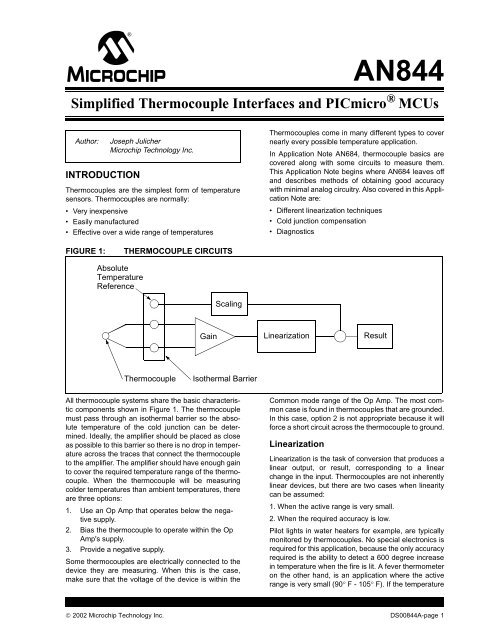
FIGURE 1: THERMOCOUPLE CIRCUITS<br />
All thermocouple systems share the basic characteristic<br />
components shown in Figure 1. The thermocouple<br />
must pass through an isothermal barrier so the absolute<br />
temperature of the cold junction can be determined.<br />
Ideally, the amplifier should be placed as close<br />
as possible to this barrier so there is no drop in temperature<br />
across the traces that connect the thermocouple<br />
to the amplifier. The amplifier should have enough gain<br />
to cover the required temperature range of the thermocouple.<br />
When the thermocouple will be measuring<br />
colder temperatures than ambient temperatures, there<br />
are three options:<br />
1. Use an Op Amp that operates below the negative<br />
supply.<br />
2. Bias the thermocouple to operate within the Op<br />
Amp's supply.<br />
3. Provide a negative supply.<br />
Some thermocouples are electrically connected to the<br />
device they are measuring. When this is the case,<br />
make sure that the voltage of the device is within the<br />
<strong>AN844</strong><br />
<strong>Simplified</strong> <strong>Thermocouple</strong> <strong>Interfaces</strong> and <strong>PICmicro</strong> ® MCUs<br />
Author: Joseph Julicher<br />
<strong>Microchip</strong> Technology Inc.<br />
Absolute<br />
Temperature<br />
Reference<br />
Gain<br />
Scaling<br />
<strong>Thermocouple</strong> Isothermal Barrier<br />
<strong>Thermocouple</strong>s come in many different types to cover<br />
nearly every possible temperature application.<br />
In Application Note AN684, thermocouple basics are<br />
covered along with some circuits to measure them.<br />
This Application Note begins where AN684 leaves off<br />
and describes methods of obtaining good accuracy<br />
with minimal analog circuitry. Also covered in this Application<br />
Note are:<br />
• Different linearization techniques<br />
• Cold junction compensation<br />
• Diagnostics<br />
Linearization<br />
Common mode range of the Op Amp. The most common<br />
case is found in thermocouples that are grounded.<br />
In this case, option 2 is not appropriate because it will<br />
force a short circuit across the thermocouple to ground.<br />
Linearization<br />
Result<br />
Linearization is the task of conversion that produces a<br />
linear output, or result, corresponding to a linear<br />
change in the input. <strong>Thermocouple</strong>s are not inherently<br />
linear devices, but there are two cases when linearity<br />
can be assumed:<br />
1. When the active range is very small.<br />
2. When the required accuracy is low.<br />
Pilot lights in water heaters for example, are typically<br />
monitored by thermocouples. No special electronics is<br />
required for this application, because the only accuracy<br />
required is the ability to detect a 600 degree increase<br />
in temperature when the fire is lit. A fever thermometer<br />
on the other hand, is an application where the active<br />
range is very small (90° F - 105° F). If the temperature<br />
© 2002 <strong>Microchip</strong> Technology Inc. DS00844A-page 1
<strong>AN844</strong><br />
gets higher than the effective range, either the thermometer<br />
is not being used correctly, or the patient<br />
needs to be in the hospital.<br />
There are many ways to linearize the thermocouple<br />
results. Figure 1 shows linearization following the gain<br />
stage. Sometimes, the linearization follows the addition<br />
of the absolute temperature reference. No matter<br />
where it occurs, or to what degree, linearization is critical<br />
to the application.<br />
Absolute Temperature Scaling<br />
<strong>Thermocouple</strong>s are relative measuring devices. In<br />
other words, they measure the temperature difference<br />
between two thermal regions. Some applications are<br />
only interested in this thermal difference, but most<br />
applications require the absolute temperature of the<br />
device under test. The absolute temperature can be<br />
FIGURE 2:<br />
Isothermal<br />
PURE ANALOG SOLUTION<br />
Block<br />
VDD<br />
NTC<br />
Thermistor<br />
-<br />
+<br />
<strong>Thermocouple</strong><br />
VREF<br />
2.5 V<br />
9.76 KΩ<br />
100 Ω<br />
2.5 KΩ<br />
19.1 KΩ<br />
1 KΩ<br />
In the analog solution, the thermocouple is biased up<br />
2.5V. This allows the thermocouple to be used to measure<br />
temperatures hotter and colder than the isothermal<br />
block. This implementaion cannot be used with a<br />
grounded thermocouple. The bias network that biases<br />
the thermocouple to 2.5V contains a thermistor. The<br />
thermistor adjusts the bias voltage making the thermocouple<br />
voltage track the absolute voltage. Both the<br />
thermistor and the thermocouple are non-linear<br />
devices, so a linearization system would have to be<br />
created that takes both curves into account.<br />
LM136-2.5<br />
RG<br />
+<br />
-<br />
10 KΩ<br />
10 KΩ<br />
-<br />
+<br />
Offset Adjust<br />
easily found by adding the thermocouple temperature<br />
to the absolute temperature of one end of the thermocouple.<br />
This can be done at any point in the thermocouple<br />
circuit. Figure 1 shows the scaling occurring after<br />
the linearization.<br />
Results<br />
The result of the thermocouple circuit is a usable indication<br />
of the temperature. Some applications simply<br />
display the temperature on a meter. Other applications<br />
perform some control or warning function. When the<br />
results are determined, the work of the thermocouple<br />
circuit is finished.<br />
Pure Analog Circuit<br />
A pure analog solution to measuring temperatures with<br />
a thermocouple is shown in Figure 2.<br />
10 KΩ<br />
<strong>Simplified</strong> Digital<br />
Output<br />
Most analog problems can be converted to a digital<br />
problem and thermocouples are no exception. If an<br />
analog-to-digital converter (ADC) were placed at the<br />
end of the analog solution shown in Figure 2, the result<br />
would be a simple digital thermometer (at least the software<br />
would be simple). However, the analog/linear circuitry<br />
could be made less expensive to build and<br />
calibrate by adding a microcontroller.<br />
DS00844A-page 2 © 2002 <strong>Microchip</strong> Technology Inc.<br />
VREF<br />
10 KΩ<br />
+<br />
10 KΩ 10 KΩ<br />
-
FIGURE 3: SIMPLIFIED DIGITAL CIRCUIT<br />
-<br />
+<br />
+5 V<br />
10 KΩ<br />
As you can see, the circuit got a lot simpler (see Figure<br />
3). This system still uses a thermistor for the absolute<br />
temperature reference, but the thermistor does not<br />
affect the thermocouple circuit. This makes the thermocouple<br />
circuit much simpler.<br />
+<br />
-<br />
<strong>AN844</strong><br />
© 2002 <strong>Microchip</strong> Technology Inc. DS00844A-page 3<br />
AN0<br />
AN1<br />
VDD<br />
<strong>PICmicro</strong> ®<br />
MICROCONTROLLER<br />
VSS
<strong>AN844</strong><br />
Hot Only or Cold Only Measurement<br />
If the application can only measure hot or cold objects,<br />
the circuit gets even simpler (see Figure 4). If only one<br />
direction is going to be used in an application, a simple<br />
difference amplifier can be used. The minimum temperature<br />
that can be measured depends on the quality of<br />
the Op Amp. If a good single supply, rail-rail Op Amp is<br />
used, the input voltage can approach 0V and temperature<br />
differences of nearly 0 degrees can be measured.<br />
To switch from hot to cold measurement, the polarity of<br />
the thermocouple wires could be switched.<br />
FIGURE 4: HOT OR COLD ONLY MEASUREMENT<br />
FAULT Detection<br />
-<br />
+<br />
+5V<br />
When thermocouples are used in automotive or aerospace<br />
applications, some sort of FAULT detection is<br />
required since a life may be depending on the correct<br />
performance of the thermocouple. <strong>Thermocouple</strong>s<br />
have a few possible failure modes that must be considered<br />
when the design is developed:<br />
1. <strong>Thermocouple</strong> wire is brittle and easily broken in<br />
high vibration environments.<br />
2. A short circuit in a thermocouple wire looks like<br />
a new thermocouple and will report the temperature<br />
of the short.<br />
3. A short to power or ground can saturate the high<br />
gain amplifiers and cause an erroneous hot or<br />
cold reading.<br />
Solutions for these problems depend on the application.<br />
Measuring the Resistance of the<br />
<strong>Thermocouple</strong><br />
The most comprehensive thermocouple diagnostic is<br />
to measure the resistance. <strong>Thermocouple</strong> resistance<br />
per unit length is published and available. If the circuit<br />
can inject some current and measure the voltage<br />
across the thermocouple, the length of the thermocouple<br />
can be determined. If no current flows, there is an<br />
open circuit. If the length changed, then the thermocouple<br />
is shorted. This type of diagnostic is best performed<br />
under the control of a microcontroller.<br />
DS00844A-page 4 © 2002 <strong>Microchip</strong> Technology Inc.<br />
-<br />
+<br />
ADC<br />
ADC
DIGITAL COLD COMPENSATION<br />
Digital cold compensation requires an absolute temperature<br />
reference. The absolute temperature reference<br />
can be from any source, but it must accurately represent<br />
the temperature of the measured end of the thermocouple.<br />
The previous examples used a thermistor in<br />
the isothermal block to measure the temperature. The<br />
analog example used the thermistor to directly affect<br />
the offset voltage of the thermocouple. The digital<br />
example uses a second ADC channel to measure the<br />
thermocouple voltage separately.<br />
FIGURE 5: THERMOCOUPLE TRANSFER FUNCTIONS<br />
Millivolts<br />
80<br />
70<br />
60<br />
50<br />
40<br />
30<br />
20<br />
10<br />
Linear Approximation<br />
The simplest method of converting the thermocouple<br />
voltage to a temperature is by linear approximation.<br />
This is simply picking a line that best approximates the<br />
voltage-temperature curve for the appropriate temperature<br />
range. For some thermocouples, this range is<br />
quite large. For others, this is very small. The range can<br />
be extended if the accuracy requirement is low. J and<br />
K thermocouples can be linearly approximated over<br />
T<br />
J<br />
E<br />
<strong>AN844</strong><br />
The formula for calculating the actual temperature<br />
when the reference temperature and thermocouple<br />
temperature are known is:<br />
Actual temperature = reference temperature + thermocouple<br />
temperature<br />
Linearization Techniques<br />
<strong>Thermocouple</strong> applications must convert the voltage<br />
output from a thermocouple into the temperature<br />
across the thermocouple. This voltage response is not<br />
linear and it is not the same for each type of thermocouple.<br />
Figure 5 shows a rough approximation of the family<br />
of thermocouple transfer functions.<br />
1000 2000 3000 4000 5000<br />
Temperature (Farenheit)<br />
their positive temperature range with a 30 degree error.<br />
For many applications this is acceptable, but to achieve<br />
a better response other techniques are required.<br />
Polynomials<br />
Coefficients are published to generate high order polynomials<br />
that describe the temperature-voltage curve<br />
for each type of thermocouple. These calculations are<br />
best performed with floating point math because there<br />
© 2002 <strong>Microchip</strong> Technology Inc. DS00844A-page 5<br />
K<br />
N<br />
R<br />
B<br />
S<br />
G<br />
C
<strong>AN844</strong><br />
are many significant figures involved. If the <strong>PICmicro</strong><br />
MCU has the program space for the libraries then this<br />
is the most general solution.<br />
TABLE 1: J THERMOCOUPLE DATA TABLE - TEMPERATURE TO VOLTS<br />
Coefficient Temperature -210° C to 760° C Temperature 760° C to 1200° C<br />
C0 0.0000000000E+00 2.9645625681E+05<br />
C1 5.0381187815E+01 -1.4976127786E+03<br />
C2 3.0475836930E-02 3.1787103924E+00<br />
C3 -8.5681065720E-05 -3.1847686701E-03<br />
C4 1.3228195295E-07 1.5720819004E-06<br />
C5 -1.7052958337E-10 -3.0691369056E-10<br />
C6 2.0948090697E-13 0.0000000000E+00<br />
C7 -1.2538395336E-16 0.0000000000E+00<br />
C8 1.5631725697E-20 0.0000000000E+00<br />
Note: v = c0 * t + c1 * t^1 + c2 * t^2 + c3 * t^3 + c4 * t^4 + c5 * t^5 + c6 * t^6 + c7 * t^7 + c8 * t^8<br />
v = volts<br />
t = temperature in C if the above table is used.<br />
Lookup Table<br />
The easiest method of linearizing the data is to build a<br />
‘lookup table.’ The lookup table should be sized to fit<br />
the available space and required accuracy. A spreadsheet<br />
can be used to convert the coefficients into the<br />
correct data table. A table will be required for each type<br />
of thermocouple used. If high accuracy (large tables)<br />
are used, it may be a good idea to minimize the number<br />
of thermocouple types.<br />
To minimize the table size, a combination of techniques<br />
may be used. A combination of tables and linear<br />
approximation could reduce the J or K error to just a<br />
few degrees.<br />
BUILDING AN ENGINE<br />
TEMPERATURE MONITOR<br />
Background<br />
One application of thermocouples is measuring engine<br />
parameters. Air-cooled engines, such as those used in<br />
aircraft, require good control of cylinder head temperature<br />
(CHT) and exhaust gas temperature (EGT). The<br />
control is typically performed by the pilot by adjusting:<br />
• Fuel mixture<br />
• Power settings<br />
• Climb/descent rate.<br />
Because mixture is used to control temperature, fuel<br />
economy is directly impacted by the ability to accurately<br />
measure the EGT. CHT is critical in air-cooled<br />
engines because of the mechanical limits of the cylinder<br />
materials. If the cylinder is cooled too fast (shock<br />
cooled) the cylinders or rings could crack, or the valves<br />
could warp. Typically, shock cooling results from a rapid<br />
descent at a low throttle setting.<br />
Device<br />
A good device for measuring these engine parameters<br />
should have a range of 300°-900° F for EGT and 300°-<br />
600° F for CHT. Additionally, diagnostics for short/open<br />
circuits are required to alert the pilot that maintenance<br />
is required. The electronics should be placed in a suitable<br />
location that has a total temperature range of -40°<br />
to +185°. This will allow the thermocouple circuitry to be<br />
simplified. The data will be displayed on a terminal program<br />
on a PC through an RS-232 interface.<br />
Amplifier<br />
The amplifier circuit is in two stages. First is a differential<br />
amplifier that provides a gain of 10 and a high<br />
impedance to the thermocouple. This is followed by a<br />
single-ended output stage that provides a gain of 25 for<br />
K thermocouples and 17 for J thermocouples. The<br />
amplifier selected is the MCP619. This device was<br />
selected for its rail-rail output and very low VOS. The<br />
thermocouple is located in a high frequency/radio frequency<br />
environment so small capacitors are used at<br />
the input and between the stages to filter out the noise.<br />
As with most RF sources, these are normally very well<br />
shielded. Since the temperatures don't change quickly,<br />
heavily filtering the signal to eliminate the noise does<br />
not affect the temperature measurement.<br />
DS00844A-page 6 © 2002 <strong>Microchip</strong> Technology Inc.
Digital Conversion and Cold<br />
Compensation<br />
The signal is converted to digital with a MCP3004 A/D<br />
converter chip. The absolute temperature is measured<br />
with a TC1046 on the third channel of the MCP3004.<br />
The data is received by a PIC16F628 and converted to<br />
a regular temperature report over an RS-232 interface.<br />
To convert from volts to temperature, the Most Significant<br />
eight bits of the conversion are used to index into<br />
a 256-entry lookup table. The remaining 2 bits are used<br />
to perform linear interpolation on the data between two<br />
adjacent points in the lookup table. Three tables are<br />
stored in the memory of the PIC16F628. These tables<br />
are for:<br />
• J - type thermocouple<br />
• K - type thermocouple<br />
• TC1046A<br />
The TC1046A has linear output, but we could easily<br />
substitute a non-linear thermistor for the same task.<br />
Lookup Table Generation<br />
Eight-bit lookup tables are generated using a spreadsheet.<br />
The polynomial values of the voltage-to-temperature<br />
curve are used to generate a voltage-totemperature<br />
conversion spreadsheet. The voltages are<br />
the predicted values from the analog-to-digital converter.<br />
A 256-entry table was constructed of ADC<br />
counts to temperatures. The temperatures ranged from<br />
zero degrees C to 535° C. Because the table can only<br />
store eight-bit values of temperature, two points were<br />
selected as pivot points. At the first point, the temperature<br />
was reduced by 255° C. At the second point, the<br />
temperature was reduced by 510° C. The final temperature<br />
can be easily reconstructed by adding the two<br />
constants back in as appropriate. Additional resolution<br />
is obtained by interpolating between two points in the 8bit<br />
table using the extra two bits from the 10-bit conversion.<br />
This will result in four times as many data points<br />
by assuming a linear response between the points in<br />
the lookup table.<br />
CONCLUSIONS<br />
<strong>Thermocouple</strong>s can be tricky devices, but when the<br />
problem is shifted from the hardware analog components<br />
into the software, they can become a lot more<br />
manageable. The only real requirement when using<br />
thermocouples is to provide a high quality amplifier to<br />
sense and scale the signal before converting it to digital<br />
form.<br />
MEMORY USAGE<br />
<strong>AN844</strong><br />
TABLE 2: SOFTWARE MEMORY USAGE<br />
Program<br />
Memory<br />
File Registers Data EEPROM<br />
1399 Words 28 Bytes 0 Bytes<br />
© 2002 <strong>Microchip</strong> Technology Inc. DS00844A-page 7
<strong>AN844</strong><br />
APPENDIX A: SCHEMATIC OF EXHAUST GAS AND CYLINDER HEAD<br />
TEMPERATURE MONITORING DEVICE<br />
U5<br />
U4<br />
+5V<br />
3<br />
Out<br />
1 In<br />
15<br />
GND<br />
2 V+<br />
+5V<br />
CR1<br />
C17<br />
C16<br />
C18<br />
C15<br />
C14<br />
C13<br />
C12<br />
Gnd<br />
Gnd<br />
C11<br />
1<br />
3<br />
2<br />
J4<br />
C8 C9<br />
C10<br />
2<br />
4<br />
6<br />
4<br />
V-<br />
C2+<br />
16<br />
VCC<br />
1 C1+<br />
6<br />
7<br />
8<br />
9<br />
1<br />
2<br />
3<br />
4<br />
5<br />
J2<br />
R18<br />
R17<br />
5<br />
14<br />
713<br />
C7<br />
C2-<br />
9 R2OUT<br />
10 T2IN<br />
3 C1-<br />
11 T1IN T1OUT<br />
12<br />
T2OUT<br />
R1OUT R1IN<br />
R2IN<br />
R9<br />
R5<br />
8<br />
+5V<br />
U1:D<br />
14<br />
12 -<br />
U1:A<br />
4<br />
2 -<br />
R1<br />
13 +<br />
R8<br />
1<br />
3 +<br />
R2<br />
U3<br />
Gain = 240<br />
K <strong>Thermocouple</strong> Channel<br />
11<br />
R11<br />
C3<br />
R10<br />
C2<br />
C1<br />
R6<br />
+5V<br />
Isothermal<br />
Area<br />
14<br />
VDD<br />
RA5/MCLR/VPP 4<br />
6<br />
RB0/INT RA0/AN0 17<br />
7 RB1/RX RA1/AN1 18<br />
8 RB2/TX RA2/AN2 1<br />
9 RB3/CCP RA3/AN3 2<br />
10 RB4/LVP RA4/TOCKI 3<br />
11 RB5<br />
12 RB6 OSC1/RA7<br />
16<br />
13 RB7 OSC2/RA6<br />
15<br />
5<br />
VSS<br />
DS00844A-page 8 © 2002 <strong>Microchip</strong> Technology Inc.<br />
R13<br />
1<br />
2<br />
3<br />
4<br />
J1<br />
+5V<br />
1<br />
CH0<br />
14<br />
VDD<br />
2<br />
3<br />
CH1<br />
13<br />
VREF<br />
CH2 AGND 12<br />
4<br />
5<br />
CH3 Clk 11<br />
DOUT 10<br />
6 DIN 9<br />
7DGND 8<br />
U6<br />
R16<br />
P1<br />
P2<br />
P3<br />
P4<br />
Y1<br />
U1:C<br />
8<br />
9 -<br />
R4<br />
R12<br />
U1:B<br />
7<br />
6 -<br />
10 +<br />
R19<br />
5 +<br />
R3<br />
+5V<br />
Gain = 160<br />
J <strong>Thermocouple</strong> Channel<br />
R15<br />
C5<br />
R14<br />
C6<br />
C4<br />
R7<br />
1 VDD<br />
2<br />
3<br />
Out<br />
Vss<br />
U2<br />
+5V<br />
J3<br />
1<br />
2<br />
3<br />
4<br />
5<br />
6<br />
C11 = 47 μF<br />
C12 = 1 μF<br />
C16, C17 = 100 pF<br />
C7, C8, C9, C10, C13, C14, C15, C16 = 0.1 μF<br />
C1, C2, C3, C4, C5 = 0.01 μF<br />
R1, R2, R3, R4 = 10 k<br />
R5, R6, R7, R16 = 100 k<br />
R8, R11, R12, R15, R19 = 1 k<br />
R9, R10 = 24 k<br />
R13, R14 = 16 k<br />
R17, R18 = 470<br />
Y1 = 6 MHz Resonator w/caps<br />
PARTS LIST:<br />
U1: MCP619<br />
U2: TC1046 Temperature Sensor<br />
U3: PIC16F628<br />
U4: MAX232<br />
U5: LM2940<br />
U6: MCP3004<br />
J1: Screw Terminal Block<br />
J2: DB9 Female<br />
J3: RJ11 6 Pin Jack<br />
J4: 5 mm Coaxial Jack
REFERENCES<br />
Application Note AN684<br />
Omega Temperature Sensing Handbook<br />
<strong>AN844</strong><br />
© 2002 <strong>Microchip</strong> Technology Inc. DS00844A-page 9
<strong>AN844</strong><br />
NOTES:<br />
DS00844A-page 10 © 2002 <strong>Microchip</strong> Technology Inc.
Note the following details of the code protection feature on <strong>PICmicro</strong> ® MCUs.<br />
• The <strong>PICmicro</strong> family meets the specifications contained in the <strong>Microchip</strong> Data Sheet.<br />
• <strong>Microchip</strong> believes that its family of <strong>PICmicro</strong> microcontrollers is one of the most secure products of its kind on the market today,<br />
when used in the intended manner and under normal conditions.<br />
• There are dishonest and possibly illegal methods used to breach the code protection feature. All of these methods, to our knowledge,<br />
require using the <strong>PICmicro</strong> microcontroller in a manner outside the operating specifications contained in the data sheet.<br />
The person doing so may be engaged in theft of intellectual property.<br />
• <strong>Microchip</strong> is willing to work with the customer who is concerned about the integrity of their code.<br />
• Neither <strong>Microchip</strong> nor any other semiconductor manufacturer can guarantee the security of their code. Code protection does not<br />
mean that we are guaranteeing the product as “unbreakable”.<br />
• Code protection is constantly evolving. We at <strong>Microchip</strong> are committed to continuously improving the code protection features of<br />
our product.<br />
If you have any further questions about this matter, please contact the local sales office nearest to you.<br />
Information contained in this publication regarding device<br />
applications and the like is intended through suggestion only<br />
and may be superseded by updates. It is your responsibility to<br />
ensure that your application meets with your specifications.<br />
No representation or warranty is given and no liability is<br />
assumed by <strong>Microchip</strong> Technology Incorporated with respect<br />
to the accuracy or use of such information, or infringement of<br />
patents or other intellectual property rights arising from such<br />
use or otherwise. Use of <strong>Microchip</strong>’s products as critical components<br />
in life support systems is not authorized except with<br />
express written approval by <strong>Microchip</strong>. No licenses are conveyed,<br />
implicitly or otherwise, under any intellectual property<br />
rights.<br />
Trademarks<br />
The <strong>Microchip</strong> name and logo, the <strong>Microchip</strong> logo, FilterLab,<br />
KEELOQ, microID, MPLAB, MXDEV, PIC, <strong>PICmicro</strong>,<br />
PICMASTER, PICSTART, PRO MATE, SEEVAL and The<br />
Embedded Control Solutions Company are registered trademarks<br />
of <strong>Microchip</strong> Technology Incorporated in the U.S.A. and<br />
other countries.<br />
dsPIC, dsPICDEM.net, ECONOMONITOR, FanSense,<br />
FlexROM, fuzzyLAB, In-Circuit Serial Programming, ICSP,<br />
ICEPIC, microPort, Migratable Memory, MPASM, MPLIB,<br />
MPLINK, MPSIM, MXLAB, PICC, PICDEM, PICDEM.net,<br />
rfPIC, Select Mode and Total Endurance are trademarks of<br />
<strong>Microchip</strong> Technology Incorporated in the U.S.A.<br />
Serialized Quick Turn Programming (SQTP) is a service mark<br />
of <strong>Microchip</strong> Technology Incorporated in the U.S.A.<br />
All other trademarks mentioned herein are property of their<br />
respective companies.<br />
© 2002, <strong>Microchip</strong> Technology Incorporated, Printed in the<br />
U.S.A., All Rights Reserved.<br />
Printed on recycled paper.<br />
<strong>Microchip</strong> received QS-9000 quality system<br />
certification for its worldwide headquarters,<br />
design and wafer fabrication facilities in<br />
Chandler and Tempe, Arizona in July 1999 and<br />
Mountain View, California in March 2002.<br />
The Company’s quality system processes and<br />
procedures are QS-9000 compliant for its<br />
<strong>PICmicro</strong> ® 8-bit MCUs, KEELOQ ® code hopping<br />
devices, Serial EEPROMs, microperipherals,<br />
non-volatile memory and analog products. In<br />
addition, <strong>Microchip</strong>’s quality system for the<br />
design and manufacture of development<br />
systems is ISO 9001 certified.<br />
© 2002 <strong>Microchip</strong> Technology Inc. DS00844A - page 11
AMERICAS<br />
Corporate Office<br />
2355 West Chandler Blvd.<br />
Chandler, AZ 85224-6199<br />
Tel: 480-792-7200 Fax: 480-792-7277<br />
Technical Support: 480-792-7627<br />
Web Address: http://www.microchip.com<br />
Rocky Mountain<br />
2355 West Chandler Blvd.<br />
Chandler, AZ 85224-6199<br />
Tel: 480-792-7966 Fax: 480-792-4338<br />
Atlanta<br />
500 Sugar Mill Road, Suite 200B<br />
Atlanta, GA 30350<br />
Tel: 770-640-0034 Fax: 770-640-0307<br />
Boston<br />
2 Lan Drive, Suite 120<br />
Westford, MA 01886<br />
Tel: 978-692-3848 Fax: 978-692-3821<br />
Chicago<br />
333 Pierce Road, Suite 180<br />
Itasca, IL 60143<br />
Tel: 630-285-0071 Fax: 630-285-0075<br />
Dallas<br />
4570 Westgrove Drive, Suite 160<br />
Addison, TX 75001<br />
Tel: 972-818-7423 Fax: 972-818-2924<br />
Detroit<br />
Tri-Atria Office Building<br />
32255 Northwestern Highway, Suite 190<br />
Farmington Hills, MI 48334<br />
Tel: 248-538-2250 Fax: 248-538-2260<br />
Kokomo<br />
2767 S. Albright Road<br />
Kokomo, Indiana 46902<br />
Tel: 765-864-8360 Fax: 765-864-8387<br />
Los Angeles<br />
18201 Von Karman, Suite 1090<br />
Irvine, CA 92612<br />
Tel: 949-263-1888 Fax: 949-263-1338<br />
New York<br />
150 Motor Parkway, Suite 202<br />
Hauppauge, NY 11788<br />
Tel: 631-273-5305 Fax: 631-273-5335<br />
San Jose<br />
<strong>Microchip</strong> Technology Inc.<br />
2107 North First Street, Suite 590<br />
San Jose, CA 95131<br />
Tel: 408-436-7950 Fax: 408-436-7955<br />
Toronto<br />
6285 Northam Drive, Suite 108<br />
Mississauga, Ontario L4V 1X5, Canada<br />
Tel: 905-673-0699 Fax: 905-673-6509<br />
WORLDWIDE SALES AND SERVICE<br />
ASIA/PACIFIC<br />
Australia<br />
<strong>Microchip</strong> Technology Australia Pty Ltd<br />
Suite 22, 41 Rawson Street<br />
Epping 2121, NSW<br />
Australia<br />
Tel: 61-2-9868-6733 Fax: 61-2-9868-6755<br />
China - Beijing<br />
<strong>Microchip</strong> Technology Consulting (Shanghai)<br />
Co., Ltd., Beijing Liaison Office<br />
Unit 915<br />
Bei Hai Wan Tai Bldg.<br />
No. 6 Chaoyangmen Beidajie<br />
Beijing, 100027, No. China<br />
Tel: 86-10-85282100 Fax: 86-10-85282104<br />
China - Chengdu<br />
<strong>Microchip</strong> Technology Consulting (Shanghai)<br />
Co., Ltd., Chengdu Liaison Office<br />
Rm. 2401, 24th Floor,<br />
Ming Xing Financial Tower<br />
No. 88 TIDU Street<br />
Chengdu 610016, China<br />
Tel: 86-28-86766200 Fax: 86-28-86766599<br />
China - Fuzhou<br />
<strong>Microchip</strong> Technology Consulting (Shanghai)<br />
Co., Ltd., Fuzhou Liaison Office<br />
Unit 28F, World Trade Plaza<br />
No. 71 Wusi Road<br />
Fuzhou 350001, China<br />
Tel: 86-591-7503506 Fax: 86-591-7503521<br />
China - Shanghai<br />
<strong>Microchip</strong> Technology Consulting (Shanghai)<br />
Co., Ltd.<br />
Room 701, Bldg. B<br />
Far East International Plaza<br />
No. 317 Xian Xia Road<br />
Shanghai, 200051<br />
Tel: 86-21-6275-5700 Fax: 86-21-6275-5060<br />
China - Shenzhen<br />
<strong>Microchip</strong> Technology Consulting (Shanghai)<br />
Co., Ltd., Shenzhen Liaison Office<br />
Rm. 1315, 13/F, Shenzhen Kerry Centre,<br />
Renminnan Lu<br />
Shenzhen 518001, China<br />
Tel: 86-755-2350361 Fax: 86-755-2366086<br />
China - Hong Kong SAR<br />
<strong>Microchip</strong> Technology Hongkong Ltd.<br />
Unit 901-6, Tower 2, Metroplaza<br />
223 Hing Fong Road<br />
Kwai Fong, N.T., Hong Kong<br />
Tel: 852-2401-1200 Fax: 852-2401-3431<br />
India<br />
<strong>Microchip</strong> Technology Inc.<br />
India Liaison Office<br />
Divyasree Chambers<br />
1 Floor, Wing A (A3/A4)<br />
No. 11, O’Shaugnessey Road<br />
Bangalore, 560 025, India<br />
Tel: 91-80-2290061 Fax: 91-80-2290062<br />
Japan<br />
<strong>Microchip</strong> Technology Japan K.K.<br />
Benex S-1 6F<br />
3-18-20, Shinyokohama<br />
Kohoku-Ku, Yokohama-shi<br />
Kanagawa, 222-0033, Japan<br />
Tel: 81-45-471- 6166 Fax: 81-45-471-6122<br />
Korea<br />
<strong>Microchip</strong> Technology Korea<br />
168-1, Youngbo Bldg. 3 Floor<br />
Samsung-Dong, Kangnam-Ku<br />
Seoul, Korea 135-882<br />
Tel: 82-2-554-7200 Fax: 82-2-558-5934<br />
Singapore<br />
<strong>Microchip</strong> Technology Singapore Pte Ltd.<br />
200 Middle Road<br />
#07-02 Prime Centre<br />
Singapore, 188980<br />
Tel: 65-6334-8870 Fax: 65-6334-8850<br />
Taiwan<br />
<strong>Microchip</strong> Technology (Barbados) Inc.,<br />
Taiwan Branch<br />
11F-3, No. 207<br />
Tung Hua North Road<br />
Taipei, 105, Taiwan<br />
Tel: 886-2-2717-7175 Fax: 886-2-2545-0139<br />
EUROPE<br />
Austria<br />
<strong>Microchip</strong> Technology Austria GmbH<br />
Durisolstrasse 2<br />
A-4600 Wels<br />
Austria<br />
Tel: 43-7242-2244-399<br />
Fax: 43-7242-2244-393<br />
Denmark<br />
<strong>Microchip</strong> Technology Nordic ApS<br />
Regus Business Centre<br />
Lautrup hoj 1-3<br />
Ballerup DK-2750 Denmark<br />
Tel: 45 4420 9895 Fax: 45 4420 9910<br />
France<br />
<strong>Microchip</strong> Technology SARL<br />
Parc d’Activite du Moulin de Massy<br />
43 Rue du Saule Trapu<br />
Batiment A - ler Etage<br />
91300 Massy, France<br />
Tel: 33-1-69-53-63-20 Fax: 33-1-69-30-90-79<br />
Germany<br />
<strong>Microchip</strong> Technology GmbH<br />
Gustav-Heinemann Ring 125<br />
D-81739 Munich, Germany<br />
Tel: 49-89-627-144 0 Fax: 49-89-627-144-44<br />
Italy<br />
<strong>Microchip</strong> Technology SRL<br />
Centro Direzionale Colleoni<br />
Palazzo Taurus 1 V. Le Colleoni 1<br />
20041 Agrate Brianza<br />
Milan, Italy<br />
Tel: 39-039-65791-1 Fax: 39-039-6899883<br />
United Kingdom<br />
<strong>Microchip</strong> Ltd.<br />
505 Eskdale Road<br />
Winnersh Triangle<br />
Wokingham<br />
Berkshire, England RG41 5TU<br />
Tel: 44 118 921 5869 Fax: 44-118 921-5820<br />
DS00844A-page 12 © 2002 <strong>Microchip</strong> Technology Inc.<br />
05/16/02


