GeoTech Report - City of Centralia
GeoTech Report - City of Centralia
GeoTech Report - City of Centralia
- No tags were found...

Create successful ePaper yourself
Turn your PDF publications into a flip-book with our unique Google optimized e-Paper software.
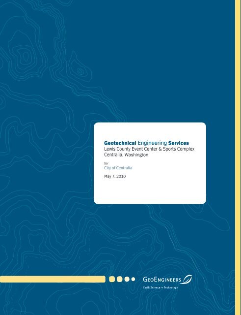
Geotechnical Engineering ServicesLewis County Event Center & Sports Complex<strong>Centralia</strong>, Washingtonfor<strong>City</strong> <strong>of</strong> <strong>Centralia</strong>May 7, 2010Earth Science + Technology
Geotechnical Engineering ServicesLewis County Event Center & Sports Complex<strong>Centralia</strong>, Washingtonfor<strong>City</strong> <strong>of</strong> <strong>Centralia</strong>May 7, 20108410 154 th Avenue NERedmond, Washington 98052425.861.6000
Table <strong>of</strong> ContentsINTRODUCTION AND PROJECT DESCRIPTION ............................................................................................ 1FIELD EXPLORATIONS AND LABORATORY TESTING ................................................................................. 1Field Explorations ................................................................................................................................... 1Laboratory Testing ................................................................................................................................. 2SITE CONDITIONS .......................................................................................................................................... 2Geology ................................................................................................................................................... 2Surface Conditions ................................................................................................................................. 2Subsurface Conditions .......................................................................................................................... 2Groundwater Conditions ........................................................................................................................ 3CONCLUSIONS AND RECOMMENDATIONS ................................................................................................ 3General ................................................................................................................................................... 3Earthquake Engineering ........................................................................................................................ 42006 International Building Code (IBC) Design Parameters ........................................................ 4Seismic Hazards .............................................................................................................................. 4Surface Fault Rupture ..................................................................................................................... 4Shallow Foundations ............................................................................................................................. 4Genera l ........................................................................................................................................... 4Allowable Bearing Pressure ............................................................................................................ 5Settlement ....................................................................................................................................... 5Lateral Resistance .......................................................................................................................... 5Construction Considerations .......................................................................................................... 5Slab-On-Grade Support .......................................................................................................................... 6Pavement Recommendations ............................................................................................................... 6Porous Pavement Design ............................................................................................................... 6Conventional Pavement Design ..................................................................................................... 8Earthwork and Structural Fill ................................................................................................................. 9Excavation Considerations ............................................................................................................. 9Stripping, Clearing and Grubbing ................................................................................................... 9Subgrade Preparation ..................................................................................................................... 9Erosion and Sedimentation Control ............................................................................................... 9Structural Fill ................................................................................................................................. 10Drainage Considerations ..................................................................................................................... 12Footing Drains ............................................................................................................................... 12Other Considerations .................................................................................................................... 12LIMITATIONS ............................................................................................................................................... 13REFERENCES .............................................................................................................................................. 13May 7, 2010 | Page iFile No. 1985-021-00
LIST OF FIGURESFigure 1. Vicinity MapFigure 2. Site PlanAPPENDICESAppendix A. Field ExplorationsFigure A-1 – Key to Exploration LogsFigures A-2 through A-5 – Log <strong>of</strong> BoringsFigures A-6 through A-22 – Log <strong>of</strong> Test PitsAppendix B. Laboratory TestingFigures B-1 through B-5 - Sieve Analysis ResultsFigures B-6 through B-7 – Atterberg Limits Test ResultsAppendix C. <strong>Report</strong> Limitations and Guidelines for UsePage ii | May 7, 2010 | GeoEngineers, Inc.File No. 1985-021-00
LEWIS COUNTY EVENT CENTER & SPORTS COMPLEX • <strong>Centralia</strong>, WashingtonINTRODUCTION AND PROJECT DESCRIPTIONThis report presents the results <strong>of</strong> our geotechnical engineering services for the Lewis CountyEvent Center & Sports Complex project in <strong>Centralia</strong>, Washington. The project is located inFort Borst Park, west <strong>of</strong> the Chehalis River. The project is shown relative to surrounding physicalfeatures on the Vicinity Map, Figure 1 and the Site Plan, Figure 2.Our understanding <strong>of</strong> the project is based on information provided by Jan Stemkoski, <strong>City</strong> Engineerfor the <strong>City</strong> <strong>of</strong> <strong>Centralia</strong>. We understand that the overall project is being jointly pursued by the city,the school district, a public facilities district and a private developer. The proposed Phase Iimprovements are illustrated in the aerial photograph below. The proposed Event Center will likelybe a two-story metal building with a 73,000-square-foot footprint and will be completed as adesign-build project. The parking improvements, totaling approximately 115,000 square feet, anda 400-foot-long roadway extension(not labeled but shown just north <strong>of</strong>the Event Center) will be designedby the city. Only Phase I parkingis shown in aerial photo; otherphases are expected to be locatedadjacent to the multi-use fields.The turf field and track, tenniscourts and multi-use fields arebeing redeveloped by others.The purpose <strong>of</strong> this study was tocomplete subsurface explorationsat the project site and toprovide geotechnical engineeringconclusions and recommendationsfor the design and construction <strong>of</strong>the proposed Event Center building,parking and roadway areas. Ourgeotechnical engineering serviceswere completed in generalaccordance with our proposal datedApril 2, 2010.Proposed project features and locationsFIELD EXPLORATIONS AND LABORATORY TESTINGField ExplorationsThe subsurface soil and groundwater conditions at the project site were evaluated by drilling fourborings (B-1 through B-4) and completing seventeen test pits (TP-1 through TP-17) on April 28 and29, 2010. The borings were completed using track-mounted, limited-access, continuous-flight,hollow-stem auger drilling equipment to depths ranging from 31½ to 46½ feet below the groundMay 7, 2010 | Page 1File No. 1985-021-00
LEWIS COUNTY EVENT CENTER & SPORTS COMPLEX • <strong>Centralia</strong>, Washingtonsurface. The test pits were completed using a rubber-tired backhoe to depths ranging from 3½ to12½ feet below the ground surface.The approximate locations <strong>of</strong> the explorations completed for this project are presented on theSite Plan, Figure 2. Details <strong>of</strong> the field exploration program and logs <strong>of</strong> the explorations arepresented in Appendix A.Laboratory TestingSoil samples were obtained during the explorations and taken to GeoEngineers’ laboratory forfurther evaluation. Selected samples were tested for the determination <strong>of</strong> moisture content,percent fines content (material passing the U.S. No. 200 sieve), grain size distribution(sieve analysis) and Atterberg limits (plasticity characteristics). A composite sample was alsotested to determine the California Bearing Ratio (CBR) for pavement design. The tests wereperformed in general accordance with the test methods <strong>of</strong> ASTM International (ASTM).A description <strong>of</strong> the laboratory testing and the test results are presented in Appendix B.SITE CONDITIONSGeologyGeologic information for the project vicinity includes a Washington Division <strong>of</strong> Geology and EarthResources map <strong>of</strong> the <strong>Centralia</strong> Quadrangle (Schasse, 1987). Mapped soils in the project vicinityconsist <strong>of</strong> alluvium. Alluvium generally consists <strong>of</strong> silt, sand and gravel deposited in streambedsand fans. The alluvium at this site was deposited in the floodplain and channel <strong>of</strong> the nearbyChehalis River.Surface ConditionsThe project site is located in Fort Borst Park, west <strong>of</strong> the Chehalis River in <strong>Centralia</strong>, Washington.The site is currently developed with improvements consisting <strong>of</strong> playfields, tennis courts,associated support buildings and facilities, and surface parking. The site is generally flat, andthere are no surface water features in the immediate project area. The layout <strong>of</strong> the existing sitefeatures and improvement are illustrated on the Site Plan, Figure 2.Subsurface ConditionsFour borings (B-1 through B-4) and seventeen test pits (TP-1 through TP-17) were completed toevaluate subsurface soil and groundwater conditions in the project area. The logs <strong>of</strong> theexplorations are presented in Appendix A.The subsurface conditions at the site generally consist <strong>of</strong> either sand and gravel deposits or siltand silty sand deposits, depending on the relative location at the site. The approximate boundarybetween these soil deposits occurs on a relatively well-defined line, as illustrated on the Site Plan,Figure 2. The location <strong>of</strong> the soil boundary line is also shown on the online Natural ResourcesConservation Service (NRCS) soil map, which is consistent with Figure 2. The soil boundary line islikely associated with the edge <strong>of</strong> a former channel <strong>of</strong> the Chehalis River; the sand and gravelPage 2 | May 7, 2010 | GeoEngineers, Inc.File No. 1985-021-00
LEWIS COUNTY EVENT CENTER & SPORTS COMPLEX • <strong>Centralia</strong>, Washingtondeposits north <strong>of</strong> the line consist <strong>of</strong> river deposits, and the silt and silty sand deposits south <strong>of</strong> theline consist <strong>of</strong> floodplain deposits.The subsurface conditions north <strong>of</strong> the soil boundary line generally consist <strong>of</strong> sand and gravel withvariable silt and cobble content (river deposits). The upper few feet have been regraded in areasand are loose with some organics, but the underlying sand and gravel layer is generally mediumdense to very dense. The sand and gravel deposits were encountered for the full depth <strong>of</strong> theexplorations. The subsurface conditions south <strong>of</strong> the soil boundary line generally consist <strong>of</strong>medium stiff to stiff silt with interbedded layers <strong>of</strong> medium dense silty sand (floodplain deposits).The upper few feet have been regraded in areas and are s<strong>of</strong>t/loose with some organics. In theexplorations near the boundary line (TP-8, TP-10 and TP-11), the thickness <strong>of</strong> the floodplaindeposits is generally less than 5 feet. Further south <strong>of</strong> the boundary line, the floodplain depositswere encountered for the full depth <strong>of</strong> the explorations. River deposits consisting <strong>of</strong> medium denseto dense silty gravel were encountered below the floodplain deposits in TP-8, TP-10 and TP-11 atdepths <strong>of</strong> 3 to 5 feet.Groundwater ConditionsIn the northern portion <strong>of</strong> the site, the soils appeared to become wet around 15 to 20 feet belowthe ground surface in the borings, with an observed groundwater level on the drilling rods at depths<strong>of</strong> about 24 to 33 feet below the ground surface. The lower groundwater levels observed in B-3and B-4 may be influenced by the nearby municipal water supply well. This well is located in thebuilding just south <strong>of</strong> the soil boundary line (north <strong>of</strong> TP-10 and TP-11) on the Site Plan, Figure 2.Perched groundwater was encountered in several test pit explorations in the southern portion <strong>of</strong>the site at depths ranging from 5 to 8 feet.Groundwater levels are expected to fluctuate with season, precipitation, well pumping andother factors.CONCLUSIONS AND RECOMMENDATIONSGeneralBased on the results <strong>of</strong> our subsurface exploration program and our engineering evaluations, it isour opinion that the Lewis County Event Center & Sports Complex project is geotechnically feasible.The following sections present our conclusions and recommendations regarding:■ Earthquake Engineering■ Shallow Foundations■ Slab-on-Grade Support■ Pavement Recommendations■ Earthwork and Structural Fill■ Drainage ConsiderationsMay 7, 2010 | Page 3File No. 1985-021-00
LEWIS COUNTY EVENT CENTER & SPORTS COMPLEX • <strong>Centralia</strong>, WashingtonWe recommend that conventional spread footings be a minimum <strong>of</strong> 36 inches wide and thatcontinuous wall footings be a minimum <strong>of</strong> 16 inches wide. Exterior footings should be founded aminimum <strong>of</strong> 18 inches below the lowest adjacent grade. Interior footings should be founded aminimum <strong>of</strong> 12 inches below the top <strong>of</strong> the slab.Allowable Bearing PressureFor foundations supported as recommended above, an allowable soil bearing pressure <strong>of</strong>4,000 pounds per square foot (psf) is recommended for spread and continuous wall footings.If the footings are founded at least 5 feet below the existing ground surface, the allowable soilbearing pressure may be increased to 6,000 psf.The allowable soil bearing pressures apply to the total <strong>of</strong> dead and long-term live loads and may beincreased by up to one-third for wind or seismic loads.SettlementThe postconstruction settlement <strong>of</strong> shallow footings supported as recommended above isestimated to be about ½ to 1 inch. Postconstruction differential settlement is estimated to beabout ½ inch between similarly loaded column footings or over a distance <strong>of</strong> about 25 feet forcontinuous wall or mat foundations. These settlements will occur rapidly, essentially as the loadsare applied.Lateral ResistanceLateral foundation loads may be resisted by passive resistance on the sides <strong>of</strong> the footings and byfriction on the bases <strong>of</strong> the footings. For footings supported in accordance with ourrecommendations, the allowable frictional resistance may be computed using a coefficient <strong>of</strong>friction <strong>of</strong> 0.45 applied to vertical dead-load forces.The allowable passive resistance may be computed using an equivalent fluid density <strong>of</strong>300 pounds per cubic foot (pcf) if the footing is poured directly against undisturbed native soils oris surrounded by structural fill. The allowable passive resistance for structural fill assumes that thestructural fill extends out from the face <strong>of</strong> the foundation element for a distance at least equal tothree times the height <strong>of</strong> the element and is compacted to at least 95 percent <strong>of</strong> the maximum drydensity (MDD) estimated in general accordance with ASTM D 1557. The above values incorporatea factor <strong>of</strong> safety <strong>of</strong> about 1.5.Construction ConsiderationsThe footing subgrade soils will be susceptible to disturbance when wet. It may be necessary topour a lean concrete “mud mat” on the bottom <strong>of</strong> the footing excavations to protect the footingsubgrade soils from water and/or wet weather during reinforcement bar placement andpreparation for concrete placement. We recommend that the condition <strong>of</strong> all footing excavationsbe observed by a geotechnical engineer prior to placement <strong>of</strong> concrete to confirm that the bearingsoils are undisturbed and are consistent with our recommendations contained in this report.May 7, 2010 | Page 5File No. 1985-021-00
LEWIS COUNTY EVENT CENTER & SPORTS COMPLEX • <strong>Centralia</strong>, WashingtonSlab-On-Grade SupportConventional slabs may be supported on-grade provided that the slabs are founded on eitherundisturbed native soils or recompacted existing soils, or on structural fill placed over these soils.For slabs designed as a beam on an elastic foundation, a modulus <strong>of</strong> subgrade reaction <strong>of</strong>50 pounds per cubic inch (pci) may be used for subgrade soils prepared as recommended.We recommend that a 6-inch-thick base course layer <strong>of</strong> 1½-inch minus clean crushed gravel withnegligible sand or silt (in conformance with Section 9-03.1(4)C, grading No. 57 <strong>of</strong> the WashingtonState Department <strong>of</strong> Transportation [WSDOT] Standard Specifications) be placed to providecapillary break and uniform slab support. Prior to placing the base course layer, the subgradeshould be pro<strong>of</strong>-rolled as described below in the “Earthwork and Structural Fill” section <strong>of</strong> thisreport. The subgrade should be recompacted to a firm and unyielding condition.Where moisture-sensitive floor coverings or moisture-sensitive equipment will be used, a vaporbarrier consisting <strong>of</strong> 10-mil plastic sheeting should be installed below the slab to reduce thepotential for migration <strong>of</strong> moisture. It may also be prudent to apply a sealer to the slab to furtherreduce the migration <strong>of</strong> moisture through the floor. The contractor should be made responsible formaintaining the integrity <strong>of</strong> the vapor barrier during construction.We estimate that postconstruction settlement <strong>of</strong> the on-grade slabs will be on the order <strong>of</strong> ½ to1 inch over a 25-foot distance.Pavement RecommendationsThe design <strong>of</strong> the pavement areas will depend significantly on whether the pavement is intended tobe traditional hot mix asphalt (HMA) or porous pavement. Our recommendations for design <strong>of</strong>porous and traditional HMA pavement sections are presented in the following sections.Porous Pavement DesignGENERAL. The design <strong>of</strong> porous pavements for stormwater management should consider storagecapacity <strong>of</strong> the pervious pavement system and infiltration rate <strong>of</strong> the subgrade soils, as well aswater quality treatment. Porous pavement may consist <strong>of</strong> porous concrete, porous HMA, porouspavers or some type <strong>of</strong> stabilized gravel surface. Our recommendations for design <strong>of</strong> porouspavement are presented in the following subsections.INFILTRATION. As discussed previously in the “Subsurface Conditions” section <strong>of</strong> this report, the sitehas two areas with significantly different subsurface conditions, as illustrated on the Site Plan,Figure 2.Two methods were used to evaluate an appropriate design (long-term) infiltration rate for thesubgrade soils. The two methods consist <strong>of</strong> correlations based on United States Department<strong>of</strong> Agriculture (USDA) soil textural classification and ASTM gradation testing, as discussed inSection 3.3.6 <strong>of</strong> the Stormwater Management Manual for Western Washington (Ecology, 2005).The ASTM gradation testing was completed on soil samples obtained at depths <strong>of</strong> 3 to 7 feet, withthe majority <strong>of</strong> the tests completed at depths <strong>of</strong> 3 to 4½ feet. Table 2 presents a summary <strong>of</strong> theestimated infiltration rates at the site.Page 6 | May 7, 2010 | GeoEngineers, Inc.File No. 1985-021-00
LEWIS COUNTY EVENT CENTER & SPORTS COMPLEX • <strong>Centralia</strong>, WashingtonTABLE 2. ESTIMATED INFILTRATION RATEAreaGeoEngineersClassificationUSDATexturalClassASTMD10(mm)SCS SeriesApproximateGroundwaterDepth (ft) 1Estimate <strong>of</strong>Infiltration Rate(inches/hour) 2USDAASTMNorth(Sand/Gravel)GP/GMSandygravel/gravellysand0.1 to0.3Spanawaygravellysandy loam15-20 2 to 10 0.5 to 6South (Silt)SM/MLSilt/ siltloam0.005to0.01 3Chehalissilty clayNotencountered
LEWIS COUNTY EVENT CENTER & SPORTS COMPLEX • <strong>Centralia</strong>, WashingtonAdditionally, landscaping areas adjacent to the pavement should be sloped to drain away from thepath so that fines in run<strong>of</strong>f from the landscaping areas can be prevented from contaminating thepavement and crushed rock and reducing the storage capacity.WATER QUALITY TREATMENT. A key element when considering porous pavement at this site isprotection <strong>of</strong> the unconfined aquifer, which is a municipal water source for the city’s well, locatedin the middle <strong>of</strong> the site.Pavement areas are pollution-generating sources, and oils occur most prominently on busystreets and busy portions <strong>of</strong> parking lots. If porous paving is used, we recommend that the upper2 feet <strong>of</strong> the underlying subgrade soils be mixed with compost at a rate <strong>of</strong> approximately10 percent compost to 90 percent soil (per volume). Compost used for amending the subgradesoils below porous pavements must meet the Washington State compost regulationsin Chapter 173-350 Washington Administrative Code (WAC), which is available athttp://www.ecy.wa.gov/programs/compost. The 2 feet <strong>of</strong> mixed soil should be recompacted to aminimum <strong>of</strong> 90 percent <strong>of</strong> the MDD per ASTM D 1557.It is our opinion that the amended subgrade soils will meet the Washington State Department <strong>of</strong>Ecology (Ecology) requirements for “treatment soils” with a minimum cation exchange capacity(CEC) <strong>of</strong> 5 microequivalents (meq). We recommend that CEC testing <strong>of</strong> the amended subgradesoils be completed during construction to verify that the soil meets Ecology requirements.The organics in the topsoil attract and bind contaminants typically found in run<strong>of</strong>f from pavementareas, and studies have shown that when stormwater is infiltrated through soils with adequateCEC, the groundwater leaving the site typically has contaminant levels equivalent to undevelopedareas. Additionally, studies have shown that porous pavement breaks down some oil pollutantsthrough the biochemical activity <strong>of</strong> microbiota that use the pavement as a substrate(Ferguson, 2005).It is our opinion that the use <strong>of</strong> porous pavements with amended subgrade soils is consistent withthe goal <strong>of</strong> wellhead protection at the site.Conventional Pavement DesignDESIGN CONSIDERATIONS. We recommend that the subgrade soils in conventional pavement areas beprepared and evaluated as described below in the “Earthwork and Structural Fill” section <strong>of</strong>this report.For conventional HMA pavement, we recommend that paved areas exposed only to automobiletraffic consist <strong>of</strong> at least 2 inches <strong>of</strong> HMA, Class ½ inch, PG 58-22 over 4 inches <strong>of</strong> crushed rockbase course. In truck traffic areas and heavy traffic volume areas, new pavement sections shouldconsist <strong>of</strong> at least 3 inches <strong>of</strong> HMA over a minimum <strong>of</strong> 6 inches <strong>of</strong> crushed rock base course.The crushed rock base course should meet the requirements <strong>of</strong> Section 9-03.9(3) <strong>of</strong> the WSDOTStandard Specifications.The crushed rock base course should be compacted to at least 95 percent <strong>of</strong> the MDD prior to theplacement <strong>of</strong> the asphalt concrete. We recommend that the geotechnical engineer observe thepro<strong>of</strong>-rolling <strong>of</strong> the compacted base course prior to paving.Page 8 | May 7, 2010 | GeoEngineers, Inc.File No. 1985-021-00
LEWIS COUNTY EVENT CENTER & SPORTS COMPLEX • <strong>Centralia</strong>, WashingtonThe pavement recommendations discussed above are based on a CBR value <strong>of</strong> 2 and typicalparking lot loading. Detailed traffic loading information was not available for the new roadwayextension at the time this report was prepared. We are available to complete pavement designcalculations for the new roadway, as necessary.WATER QUALITY TREATMENT. Bioswales may be used to provide water quality treatment andinfiltration for run<strong>of</strong>f originating from conventional pavement. If bioswales are used, werecommend that they be designed using the infiltration rates previously presented above.GeoEngineers can provide references for soil mixes for bioswales if needed.Earthwork and Structural FillExcavation ConsiderationsWe anticipate that the on-site soils may be excavated with conventional excavation equipment,such as trackhoes or dozers. Based on the alluvial origin <strong>of</strong> the soils, cobbles and boulders arelikely to be present. During construction, the contractor should be prepared to deal with cobblesand boulders as well as debris from previous site development.Stripping, Clearing and GrubbingWe recommend that all new pavement and structure areas be stripped <strong>of</strong> organic-rich soils (sod,grass and topsoil), vegetation and any existing pavement/structures. Any remaining below-gradeelements from previous site development, if present, should also be removed. Based on ourobservations, we anticipate that stripping depths will be generally about 6 to 12 inches. Strippingdepths will be locally greater where large trees are cleared and grubbed.Subgrade PreparationThe exposed subgrade in new structure and conventional pavement areas should be evaluatedafter site grading is complete. Pro<strong>of</strong>-rolling with heavy, rubber-tired construction equipment shouldbe used for this purpose during dry weather and if access for this equipment is practical.Probing should be used to evaluate the subgrade during periods <strong>of</strong> wet weather or if access is notfeasible for construction equipment. S<strong>of</strong>t areas identified during pro<strong>of</strong>-rolling or probing should beexcavated and replaced with compacted structural fill.Erosion and Sedimentation ControlPotential sources or causes <strong>of</strong> erosion and sedimentation depend upon construction methods,slope length and gradient, amount <strong>of</strong> soil exposed and/or disturbed, soil type, constructionsequencing and weather. Implementing an erosion and sedimentation control plan will reducethe project impact on erosion-prone areas. The plan should be designed in accordance withapplicable city, county and/or state standards. The plan should incorporate basic planningprinciples including:■ Scheduling grading and construction to reduce soil exposure;■ Retaining existing pavement whenever feasible;■ Revegetating or mulching denuded areas;■ Directing run<strong>of</strong>f away from denuded areas;May 7, 2010 | Page 9File No. 1985-021-00
LEWIS COUNTY EVENT CENTER & SPORTS COMPLEX • <strong>Centralia</strong>, Washington■ Decreasing run<strong>of</strong>f velocities;■ Preparing drainage ways and outlets to handle concentrated or increased run<strong>of</strong>f;■ Confining sediment to the project site; and■ Inspecting and maintaining control measures frequently.Temporary erosion protection should be used and maintained in areas with exposed or disturbedsoils to help reduce erosion and reduce transport <strong>of</strong> sediment to adjacent areas and receivingwaters. Permanent erosion protection can be provided by paving, structure construction orlandscape planting.Until the permanent erosion protection is established and the site is stabilized, site monitoringshould be performed by qualified personnel to evaluate the effectiveness <strong>of</strong> the erosion controlmeasures and to repair and/or modify them as appropriate. Provisions for modifications to theerosion control system based on monitoring observations should be included in the erosion andsedimentation control plan.Structural FillGENERAL. Materials placed to support structures or building pads and placed below pavements andsidewalks are classified as structural fill for the purposes <strong>of</strong> this report. The required quality <strong>of</strong>structural fill material varies depending upon its use, as discussed in previous sections andsummarized below:■ During periods <strong>of</strong> dry weather, structural fill should, at a minimum, meet the criteria forcommon borrow, WSDOT Standard Specifications Section 9-03.14(3).■ During wet weather, if compaction is difficult using common borrow, structural backfill shouldmeet the criteria for gravel borrow, WSDOT Standard Specifications Section 9-03.14(1), withthe additional restriction that the fines content be limited to no more than 5 percent.■ Structural fill placed around footing drains should meet the requirements <strong>of</strong> gravel backfill fordrains per WSDOT Standard Specifications Section 9-03.12(4).■ Structural fill placed for the crushed rock base course below conventional pavements shouldmeet the criteria for WSDOT Standard Specifications Section 9-03.9(3).■ Structural fill placed for the crushed rock subbase below porous pavements should meet thecriteria for shoulder ballast, WSDOT Standard Specifications Section 9-03.9(2).■ Compost used for amending the subgrade soils below porous pavements must meet theWashington State compost regulations in Chapter 173-350 WAC, which is available athttp://www.ecy.wa.gov/programs/compost.USE OF ON-SITE SOILS. The on-site soils encountered in the explorations contain a high percentage <strong>of</strong>fines and are moisture-sensitive, particularly in the southern half <strong>of</strong> the site. During dry weather,soils at the site may be suitable for reuse as common borrow, provided they can be properlymoisture-conditioned. Some soils in the northern area <strong>of</strong> the site may also meet the criteria forgravel borrow. If the contractor intends to use on-site soils for structural fill, it will be important tocover stockpiles to prevent them from becoming saturated during periods <strong>of</strong> rainfall.Page 10 | May 7, 2010 | GeoEngineers, Inc.File No. 1985-021-00
LEWIS COUNTY EVENT CENTER & SPORTS COMPLEX • <strong>Centralia</strong>, WashingtonFILL PLACEMENT AND COMPACTION CRITERIA. Structural fill should be mechanically compacted to a firmand unyielding condition. Structural fill should be placed in loose lifts not exceeding 8 to 10 inchesin thickness. Each lift should be conditioned to the proper moisture content and compacted to thespecified density before placing subsequent lifts. Structural fill should be compacted to thefollowing criteria:■ Structural fill placed below floor slabs and footings should be compacted to 95 percent <strong>of</strong> theMDD estimated in general accordance with ASTM D 1557.■ Structural fill in conventional pavement areas, including utility trench backfill, should becompacted to 90 percent <strong>of</strong> the MDD estimated in general accordance with ASTM D 1557,except that the upper 2 feet <strong>of</strong> fill below final subgrade should be compacted to 95 percent <strong>of</strong>the MDD.■ Structural fill placed as crushed rock base course below conventional pavements should becompacted to 95 percent <strong>of</strong> the MDD estimated in general accordance with ASTM D 1557.■ Structural fill below permeable pavement areas should be compacted to 85 to 90 percent <strong>of</strong>the MDD (ASTM D 1557) to maintain void space for infiltration and drainage.We recommend that a geotechnical engineer be present during pro<strong>of</strong>-rolling and/or probing <strong>of</strong> theexposed subgrade soils, and during placement <strong>of</strong> structural fill. The geotechnical engineer shouldevaluate the adequacy <strong>of</strong> the subgrade soils and identify areas needing further work, perform inplacemoisture-density tests in the fill to evaluate whether the work is being done in accordancewith the compaction specifications, and advise on any modifications to procedures that may beappropriate for the prevailing conditions.WEATHER CONSIDERATIONS. The on-site soils generally contain a high percentage <strong>of</strong> fines (silt) andare moisture-sensitive, particularly those soils in the southern half <strong>of</strong> the site. When the moisturecontent <strong>of</strong> these soils is more than a few percent above the optimum moisture content, theybecome muddy and unstable. Operation <strong>of</strong> equipment in these conditions will be difficult, and therequired compaction criteria will not be achieved. Additionally, disturbance <strong>of</strong> near-surface soilsshould be expected if earthwork is completed during periods <strong>of</strong> wet weather. During dry weather,the soils will: (1) be less susceptible to disturbance; (2) provide better support for constructionequipment; and (3) be more likely to meet the required compaction criteria.The wet weather season in western Washington generally begins in October and continues throughMay; however, periods <strong>of</strong> wet weather may occur during any month <strong>of</strong> the year. If wet weatherearthwork is unavoidable, we recommend that the following steps be taken should thenear-surface soil conditions begin to deteriorate:■ The ground surface should be graded so that areas <strong>of</strong> ponded water do not develop.The contractor should take measures to prevent surface water from collecting in excavationsand trenches. Measures should be implemented to remove surface water from the work area.■ Earthwork activities should not take place during periods <strong>of</strong> heavy precipitation.■ The contractor should take necessary measures to prevent on-site soils and soils to be used asfill from becoming wet or unstable. These measures may include the use <strong>of</strong> plastic sheeting,sumps with pumps, and grading. The site soils should not be left uncompacted and exposed toMay 7, 2010 | Page 11File No. 1985-021-00
LEWIS COUNTY EVENT CENTER & SPORTS COMPLEX • <strong>Centralia</strong>, Washingtonmoisture. Sealing the surficial soils by rolling with a smooth-drum roller prior to periods <strong>of</strong>precipitation will help reduce the extent to which these soils become wet or unstable.■ Construction traffic should be restricted to specific areas <strong>of</strong> the site, preferably areas that aresurfaced with working pad materials not susceptible to wet weather disturbance.Construction activities should be scheduled so that the length <strong>of</strong> time that soils are left exposed tomoisture is reduced to the extent practicable.Drainage ConsiderationsFooting DrainsWe recommend that perimeter footing drains be installed around the new Event Center building.The perimeter drains should be installed at the base <strong>of</strong> the exterior footings. The perimeter drainsshould be provided with cleanouts and should consist <strong>of</strong> at least 4-inch-diameter perforated pipeplaced on a 4-inch bed <strong>of</strong>, and surrounded by 6 inches <strong>of</strong>, drainage material enclosed in anon-woven geotextile fabric such as Mirafi 140N (or approved equivalent) to prevent fine soil frommigrating into the drainage material. The footing drainpipe should be installed at least 18 inchesbelow the top <strong>of</strong> the adjacent floor slab. The drainage material should consist <strong>of</strong> gravel backfill fordrains conforming to Section 9-03.12(4) <strong>of</strong> the WSDOT Standard Specifications.We recommend that the drainpipe consist <strong>of</strong> either heavy-wall solid pipe (SDR-35 polyvinylchloride [PVC], or equivalent) or rigid corrugated smooth interior polyethylene pipe (ADS N-12,or equivalent). We also recommend against using flexible tubing for footing drainpipes.The perimeter drains should be sloped to drain by gravity, if practicable, to a suitable dischargepoint, preferably a storm drain or a water treatment bioswale. We recommend that the cleanoutsbe covered and be placed in flush-mounted utility boxes. Water collected in ro<strong>of</strong> downspout linesmust not be routed to the footing drain lines.Other ConsiderationsThe soils exposed in excavations will be moisture-sensitive and susceptible to disturbance fromconstruction activities, especially when water is present on the subgrade. A system <strong>of</strong> curbs,berms, drainage ditches and swales should be installed around the perimeter <strong>of</strong> the excavation tointercept and collect surface water.We recommend that all surfaces be sloped to drain away from the proposed building area.Pavement surfaces and open space areas should be sloped such that the surface water iscollected and routed to suitable discharge points.Ro<strong>of</strong> drains should be connected to tightlines that discharge into the storm sewer disposalsystem or to water treatment bioswales. The ro<strong>of</strong> drains should be kept separate from the footingdrain lines.Page 12 | May 7, 2010 | GeoEngineers, Inc.File No. 1985-021-00
LEWIS COUNTY EVENT CENTER & SPORTS COMPLEX • <strong>Centralia</strong>, WashingtonLIMITATIONSWe have prepared this report for the exclusive use <strong>of</strong> the <strong>City</strong> <strong>of</strong> <strong>Centralia</strong> for the Lewis CountyEvent Center & Sports Complex project in <strong>Centralia</strong>, Washington. The data should be provided toprospective contractors for their bidding or estimating purposes, but our report and interpretationsshould not be construed as a warranty <strong>of</strong> the subsurface conditions.Within the limitations <strong>of</strong> scope, schedule and budget, our services have been executed inaccordance with generally accepted practices in the field <strong>of</strong> geotechnical engineering in this areaat the time this report was prepared. No warranty or other conditions, express or implied, shouldbe understood.Any electronic form, facsimile or hard copy <strong>of</strong> the original document (email, text, table, and/orfigure), if provided, and any attachments are only a copy <strong>of</strong> the original document. The originaldocument is stored by GeoEngineers, Inc. and will serve as the <strong>of</strong>ficial document <strong>of</strong> record.Please refer to Appendix C titled “<strong>Report</strong> Limitations and Guidelines for Use” for additionalinformation pertaining to use <strong>of</strong> this report.REFERENCESFerguson, Bruce K., “Porous Pavements.”International Code Council, 2009, “International Building Code.”Natural Resources Conservation Service (online geographic information system [GIS] application)URL: http://websoilsurvey.nrcs.usda.gov/app/WebSoilSurvey.aspxSchasse, Henry W., 1987, Washington Division <strong>of</strong> Geology and Earth Resources, “Geologic Map <strong>of</strong>the <strong>Centralia</strong> Quadrangle, Washington,” Open File <strong>Report</strong> 87-11.United States Geological Survey, National Seismic Hazard Mapping Project s<strong>of</strong>tware, 2002 data.United States Geological Survey, “Quaternary Fault and Fold Database <strong>of</strong> the United States,Hoquiam 1°x2°Sheet,” accessed viahttp://earthquake.usgs.gov/hazards/qfaults/wa/hoq.html on May 3, 2010.Washington State Department <strong>of</strong> Ecology, 2005, “Stormwater Management Manual for WesternWashington.”Washington State Department <strong>of</strong> Transportation, 2010, “Standard Specifications for Road, Bridgeand Municipal Construction.”May 7, 2010 | Page 13File No. 1985-021-00
Office: RED Path: P:\0\0186835\GIS\018683500_F1.mxd Map Revised: May 4, 2010 MM2Spring LnAlcott DrBlanchard RdScammonKarla CtMayberry RdA Tennyson DrC rreekSearle DrGalvin RdEshom RdEdgewood LnGreenwood LnPrill RdCooks Hill RdColonial DrGraf RdFords Prairie AveFieldcrest AveCowlitz RdPheasant RdMason AveChehalis RiverScammon Creek RdSouth t B rranch Scammon C rreekCedar Ridge DrBorst AveRussell RdMount Vista RdOakland AveW a s h i n g t o n§¨¦ 405 §¨¦ 90§¨¦ §¨¦ 5 82§¨¦ 84N Scheuber RdI d a h oO r e g o nJalyn StTaylor StHarrison AveW Reynolds AveBryden AveS Scheuber RdCaveness DrNotes:1. The locations <strong>of</strong> all features shown are approximate.2. This drawing is for information purposes. It is intended to assist inshowing features discussed in an attached document. GeoEngineers, Inc.cannot guarantee the accuracy and content <strong>of</strong> electronic files. The masterfile is stored by GeoEngineers, Inc. and will serve as the <strong>of</strong>ficial record <strong>of</strong>this communication.3. It is unlawful to copy or reproduce all or any part there<strong>of</strong>, whether forpersonal use or resale, without permission.Data Sources: ESRI Data & Maps, Street Maps 2005Transverse Mercator, Zone 10 N North, North American Datum 1983North arrow oriented to grid northLanding WaySITESandy LnAllen AveLeisure LnLinda LnFort Borst ParkMilitary RdJohnson RdNick RdIndustrial DrView AveMount Vista RdMellen StBelmont AveHaviland StHorseshoe LakeLum RdEckerson RdW High StFort Borst LakeHayes LakeRiverside Park§¨¦ 5 Plummer LakeUV 507Ellsbury StAirport RdBlair RdLewis StW Bridge StAurora StAlexander StW Main StChina CreekW Chestnut StMarsh AveLong RdElm StAlder StBrotherson RdTilley AveYew StHemlock StChristy LnDickey RdN StM StW 1st StW Locust StS Cedar StS Ash StN M StS King StSouth StWoodland AveL StL StN Cedar StN Ash StK StW Pear StHamilton AveJefferson StJ StW 2nd StSkoo k kumchuck R iW 6th StH StW 4th StW 3rd StG StF StE StEdison Elementary SchoolN King StJ StW 5th StS Oak StW Pine StN Washington AveW Summa StDixon RdN Oak StS Rock StW Plum StS Pearl StS Tower AveHillview AveW 7th StW Chestnut StE Floral Stµ2,000 02,000FeetVicinity MapW River RdW 5th StN Rock StS Silver StN Iron StW Main StGrand AveHillkress AveS Gold StField AveE Summa StLewis County Event Center & Sports Complex<strong>Centralia</strong>, WashingtonS Gold StFigure 1State StKresky Aveiv e rr
Notes1. The locations <strong>of</strong> all features shown are approximate.2. This drawing is for information purposes. It is intended to assist in showingfeatures discussed in an attached document. GeoEngineers, Inc. can not guaranteethe accuracy and content <strong>of</strong> electronic files. The master file is stored byGeoEngineers, Inc. and will serve as the <strong>of</strong>ficial record <strong>of</strong> this communication.Reference: Aerial photo provided by <strong>City</strong> <strong>of</strong> <strong>Centralia</strong>.Soil Data from National Resource Conservation Service data:http://websoilsurvey.nrcs.usda.gov/app/WebSoilSurvey.aspxB-1TP-1LegendBoring by GeoEngineersTest Pit by GeoEngineersApproximate Boundary between Soil Types(from NRCS Data and available explorations)200 0200FEETSite PlanLewis County Event Center & Sports Complex<strong>Centralia</strong>, WashingtonFigure 2
Type Name <strong>of</strong> Services HereName <strong>of</strong> Project HereforType Client Name HereType Date <strong>of</strong> <strong>Report</strong> HereEarth Science + Technology
APPENDIX AField Explorations
APPENDIX AFIELD EXPLORATIONSGeneralSubsurface conditions at the site were explored by drilling four borings (B-1 through B-4) andcompleting seventeen test pits (TP-1 through TP-17). The borings were completed to depthsranging from about 31½ to 46½ feet below the existing ground surface. The drilling wasperformed by Boretec, Inc. on April 29, 2010. The test pits were completed to depths rangingfrom about 3½ to 12½ feet below the ground surface. The test pits were excavated byKelly’s Excavating on April 28 and April 29, 2010.The locations and elevations <strong>of</strong> the explorations were estimated by taping/pacing from existing sitefeatures. The approximate locations <strong>of</strong> the explorations are shown on the Site Plan, Figure 2.BoringsThe borings were completed using track-mounted, continuous-flight, hollow-stem auger drillingequipment. The borings were continuously monitored by geotechnical engineer from our firm whoexamined and classified the soils encountered, obtained representative soil samples, observedgroundwater conditions and prepared a detailed log <strong>of</strong> each exploration.The soils encountered in the borings were sampled at 5-foot vertical intervals with a 2-inch outsidediameter split-barrel standard penetration test (SPT) sampler. The samples were obtained bydriving the sampler 18 inches into the soil with a 140-pound rope and cathead hammer free-falling30 inches. The number <strong>of</strong> blows required for each 6 inches <strong>of</strong> penetration was recorded. The blowcount (“N-value”) <strong>of</strong> the soil was calculated as the number <strong>of</strong> blows required for the final 12 inches<strong>of</strong> penetration. This resistance, or N-value, provides a measure <strong>of</strong> the relative density <strong>of</strong> granularsoils and the relative consistency <strong>of</strong> cohesive soils. Where very dense soil conditions precludeddriving the full 18 inches, the penetration resistance for the partial penetration was entered on thelogs. The blow counts are shown on the boring logs at the respective sample depths.Soils encountered in the borings were visually classified in general accordance with theclassification system described in Figure A-1. A key to the boring log symbols is also presented inFigure A-1. The logs <strong>of</strong> the explorations are presented in Figures A-2 through A-5. The logs arebased on our interpretation <strong>of</strong> the field and laboratory data and indicate the various types <strong>of</strong> soilsand groundwater conditions encountered. The logs also indicate the depths at which these soilsor their characteristics change, although the change may actually be gradual. If the changeoccurred between samples, it was interpreted. The densities noted on the logs are based on theblow count data obtained in the borings, difficulty in excavation and judgment based on theconditions encountered.Observations <strong>of</strong> groundwater conditions were made during drilling, and the groundwater conditionsencountered during drilling are presented on the boring logs. The observed groundwaterconditions represent a short-term condition and may or may not be representative <strong>of</strong> the long-termMay 7, 2010 | Page A-1File No. 1985-021-00
groundwater conditions at the site. Groundwater conditions observed during drilling should beconsidered approximate.Borings were backfilled in accordance with Washington State Department <strong>of</strong> Ecology regulations.Test PitsThe test pits were excavated using a rubber-tired backhoe. The test pits were continuouslyobserved by a geotechnical engineer from our firm who examined and classified the soilsencountered, obtained representative soil samples, observed groundwater conditions andprepared a detailed log <strong>of</strong> each test pit.Soils encountered in the test pits were visually classified in general accordance with theclassification system described in Figure A-1. A key to the exploration log symbols is alsopresented in Figure A-1. The logs <strong>of</strong> the test pits are presented in Figures A-6 through A-22.The logs reflect our interpretation <strong>of</strong> the field conditions and the results <strong>of</strong> laboratory testing andevaluation <strong>of</strong> samples. They also indicate the depths at which the soil types or their characteristicschange, although the change may actually be gradual.The test pits were backfilled with the excavated soils and compacted to the extent practicable withthe bucket <strong>of</strong> the excavator. The fill will not behave as structural fill and will likely need to berecompacted during construction.Page A-2 | May 7, 2010 | GeoEngineers, Inc.File No. 1985-021-00
SOIL CLASSIFICATION CHARTADDITIONAL MATERIAL SYMBOLSMAJOR DIVISIONSSYMBOLSGRAPH LETTERTYPICALDESCRIPTIONSSYMBOLSGRAPH LETTERTYPICALDESCRIPTIONSGRAVELANDGRAVELLYSOILSCLEANGRAVELS(LITTLE OR NO FINES)GWGPWELL-GRADED GRAVELS, GRAVEL -SAND MIXTURESPOORLY-GRADED GRAVELS, GRAVEL -SAND MIXTURESCCACCement ConcreteAsphalt ConcreteCOARSEGRAINEDSOILSMORE THAN 50%RETAINED ON NO.200 SIEVEMORE THAN 50% OFCOARSE FRACTIONRETAINED ON NO. 4SIEVESANDANDSANDYSOILSGRAVELS WITHFINES(APPRECIABLE AMOUNTOF FINES)CLEAN SANDS(LITTLE OR NO FINES)GMGCSWSPSILTY GRAVELS, GRAVEL - SAND - SILTMIXTURESCLAYEY GRAVELS, GRAVEL - SAND -CLAY MIXTURESWELL-GRADED SANDS, GRAVELLYSANDSPOORLY-GRADED SANDS, GRAVELLYSANDCRTSCrushed Rock/Quarry SpallsTopsoil/Forest Duff/SodMeasured groundwater level inexploration, well, or piezometerFINEGRAINEDSOILSMORE THAN 50% OFCOARSE FRACTIONPASSING NO. 4SIEVESILTSANDCLAYSSANDS WITHFINES(APPRECIABLE AMOUNTOF FINES)LIQUID LIMITLESS THAN 50SMSCMLCLOLSILTY SANDS, SAND - SILT MIXTURESCLAYEY SANDS, SAND - CLAYMIXTURESINORGANIC SILTS, ROCK FLOUR,CLAYEY SILTS WITH SLIGHTPLASTICITYINORGANIC CLAYS OF LOW TOMEDIUM PLASTICITY, GRAVELLYCLAYS, SANDY CLAYS, SILTY CLAYS,LEAN CLAYSORGANIC SILTS AND ORGANIC SILTYCLAYS OF LOW PLASTICITYGroundwater observed at time <strong>of</strong>explorationPerched water observed at time <strong>of</strong>explorationMeasured free product in well orpiezometerGraphic Log ContactDistinct contact between soil strata orgeologic unitsMORE THAN 50%PASSING NO. 200SIEVEMHINORGANIC SILTS, MICACEOUS ORDIATOMACEOUS SILTY SOILSApproximate location <strong>of</strong> soil stratachange within a geologic soil unitSILTSANDCLAYSHIGHLY ORGANIC SOILSLIQUID LIMITGREATER THAN 50CHOHPTINORGANIC CLAYS OF HIGHPLASTICITYORGANIC CLAYS AND SILTS OFMEDIUM TO HIGH PLASTICITYPEAT, HUMUS, SWAMP SOILS WITHHIGH ORGANIC CONTENTSMaterial Description ContactDistinct contact between soil strata orgeologic unitsApproximate location <strong>of</strong> soil stratachange within a geologic soil unitNOTE: Multiple symbols are used to indicate borderline or dual soil classificationsSampler Symbol Descriptions2.4-inch I.D. split barrelStandard Penetration Test (SPT)Shelby tubePistonDirect-PushBulk or grabBlowcount is recorded for driven samplers as the number<strong>of</strong> blows required to advance sampler 12 inches (ordistance noted). See exploration log for hammer weightand drop.A "P" indicates sampler pushed using the weight <strong>of</strong> thedrill rig.%FALCACPCSDSHAMCMDOCPMPPSATXUCVSNSSSMSHSNTLaboratory / Field TestsPercent finesAtterberg limitsChemical analysisLaboratory compaction testConsolidation testDirect shearHydrometer analysisMoisture contentMoisture content and dry densityOrganic contentPermeability or hydraulic conductivityPocket penetrometerSieve analysisTriaxial compressionUnconfined compressionVane shearSheen ClassificationNo Visible SheenSlight SheenModerate SheenHeavy SheenNot TestedNOTE: The reader must refer to the discussion in the report text and the logs <strong>of</strong> explorations for a proper understanding <strong>of</strong> subsurface conditions.Descriptions on the logs apply only at the specific exploration locations and at the time the explorations were made; they are not warranted to berepresentative <strong>of</strong> subsurface conditions at other locations or times.KEY TO EXPLORATION LOGSFIGURE A-1
DrilledStart4/29/2010End4/29/2010TotalDepth (ft)46.5Logged ByChecked ByJTMTBDrillerBoretec Inc.DrillingMethodHollow Stem AugerSurface Elevation (ft)Vertical DatumUndeterminedHammerDataRope and Cathead140 (lb) 30-inch DropDrillingEquipmentTrack RigEasting (X)Northing (Y)Notes:SystemDatumGroundwaterDate Measured4/29/2010Depth toWater (ft)24.0Elevation (ft)FIELD DATAElevation (feet)Depth (feet)IntervalRecovered (in)Blows/footCollected SampleSample NameTestingWater LevelGraphic LogGroupClassificationMATERIALDESCRIPTIONMoistureContent, %Dry Density,(pcf)REMARKS0ACRXSM1/2 " asphalt concrete2" base coarseBrown silty fine to medium sand with gravel(loose to medium dense, moist) (fill)53151GP-GMBrown to gray fine to coarse gravel with silt,sand and cobbles (medium dense to verydense, moist)Change in drilling at 5.5'(Harder drilling)Redmond: Date:5/6/10 Path:W:\REDMOND\PROJECTS\1\1985021\00\GINT\198502100LOGS.GPJ DBTemplate/LibTemplate:GEOENGINEERS8.GDT/GEI8_GEOTECH_STANDARD1015204443150/4"50/6"23425Notes: Please see Figure A-1 for explanation <strong>of</strong> symbols.Log <strong>of</strong> Boring B-1Project: Lewis County Event & Sports ComplexProject Location: <strong>Centralia</strong>, WashingtonProject Number: 1985-021-00Pounding on gravelPounding on cobblePounding on cobbleWater observed in augersPounding on gravelFigure A-2Sheet 1 <strong>of</strong> 2
FIELD DATAElevation (feet)Depth (feet)IntervalRecovered (in)Blows/footCollected SampleSample NameTestingWater LevelGraphic LogGroupClassificationMATERIALDESCRIPTIONMoistureContent, %Dry Density,(pcf)REMARKS2518325SA; %F; MCFewer cobbles16SA; %F = 73012516Pounding on gravelSP-SMGray fine to medium sand with silt and gravel(dense to very dense, wet)3518197Possible heave-blowcount unreliableRedmond: Date:5/6/10 Path:W:\REDMOND\PROJECTS\1\1985021\00\GINT\198502100LOGS.GPJ DBTemplate/LibTemplate:GEOENGINEERS8.GDT/GEI8_GEOTECH_STANDARD4045181650/2"90Notes: Please see Figure A-1 for explanation <strong>of</strong> symbols.89Log <strong>of</strong> Boring B-1 (continued)Project: Lewis County Event & Sports ComplexProject Location: <strong>Centralia</strong>, WashingtonProject Number: 1985-021-00Figure A-2Sheet 2 <strong>of</strong> 2
DrilledStart4/29/2010End4/29/2010TotalDepth (ft)31.5Logged ByChecked ByJTMTBDrillerBoretec Inc.DrillingMethodHollow Stem AugerSurface Elevation (ft)Vertical DatumUndeterminedHammerDataRope and Cathead140 (lb) 30-inch DropDrillingEquipmentTrack RigEasting (X)Northing (Y)Notes:SystemDatumGroundwaterDate Measured4/29/2010Depth toWater (ft)24.0Elevation (ft)FIELD DATAElevation (feet)Depth (feet)IntervalRecovered (in)Blows/footCollected SampleSample NameTestingWater LevelGraphic LogGroupClassificationMATERIALDESCRIPTIONMoistureContent, %Dry Density,(pcf)REMARKS0SMBrown silty fine to medium sand with gravel andtrace organics (loose, moist)GPBrownish gray to gray fine to coarse gravel withsilt, sand and cobbles (medium dense todense, moist)53261Pounding on gravelRedmond: Date:5/6/10 Path:W:\REDMOND\PROJECTS\1\1985021\00\GINT\198502100LOGS.GPJ DBTemplate/LibTemplate:GEOENGINEERS8.GDT/GEI8_GEOTECH_STANDARD1015318334023SP-SM206 29425Notes: Please see Figure A-1 for explanation <strong>of</strong> symbols.Gray fine to coarse sand with silt and gravel(medium dense to dense, wet)Log <strong>of</strong> Boring B-2Project: Lewis County Event & Sports ComplexProject Location: <strong>Centralia</strong>, WashingtonProject Number: 1985-021-00Pounding on gravelPounding on gravelWater observed in augersFigure A-3Sheet 1 <strong>of</strong> 2
FIELD DATAElevation (feet)Depth (feet)IntervalRecovered (in)Blows/footCollected SampleSample NameTestingWater LevelGraphic LogGroupClassificationMATERIALDESCRIPTIONMoistureContent, %Dry Density,(pcf)REMARKS2518495SA: %F, MC11SA: %F = 6SPGray fine to coarse sand with gravel (dense tovery dense, wet)3018506%F, MC21%F = 5Redmond: Date:5/6/10 Path:W:\REDMOND\PROJECTS\1\1985021\00\GINT\198502100LOGS.GPJ DBTemplate/LibTemplate:GEOENGINEERS8.GDT/GEI8_GEOTECH_STANDARDNotes: Please see Figure A-1 for explanation <strong>of</strong> symbols.Log <strong>of</strong> Boring B-2 (continued)Project: Lewis County Event & Sports ComplexProject Location: <strong>Centralia</strong>, WashingtonProject Number: 1985-021-00Figure A-3Sheet 2 <strong>of</strong> 2
DrilledStart4/29/2010End4/29/2010TotalDepth (ft)31.5Logged ByChecked ByJTMTBDrillerBoretec Inc.DrillingMethodHollow Stem AugerSurface Elevation (ft)Vertical DatumUndeterminedHammerDataRope and Cathead140 (lb) 30-inch DropDrillingEquipmentTrack RigEasting (X)Northing (Y)Notes:SystemDatumGroundwaterDate Measured4/29/2010Depth toWater (ft)27.0Elevation (ft)FIELD DATAElevation (feet)Depth (feet)IntervalRecovered (in)Blows/footCollected SampleSample NameTestingWater LevelGraphic LogGroupClassificationMATERIALDESCRIPTIONMoistureContent, %Dry Density,(pcf)REMARKS0SMBrown silty fine to medium sand with gravel andtrace organics (loose, moist)GPBrownish gray fine to coarse gravel with sand,cobbles and trace silt (medium dense todense, moist to wet)53521Pounding on gravelRedmond: Date:5/6/10 Path:W:\REDMOND\PROJECTS\1\1985021\00\GINT\198502100LOGS.GPJ DBTemplate/LibTemplate:GEOENGINEERS8.GDT/GEI8_GEOTECH_STANDARD1015205318414940234SP-SM25Notes: Please see Figure A-1 for explanation <strong>of</strong> symbols.Becomes wetGray fine to coarse sand with silt and gravel(very dense, wet)Log <strong>of</strong> Boring B-3Project: Lewis County Event & Sports ComplexProject Location: <strong>Centralia</strong>, WashingtonProject Number: 1985-021-00Pounding on gravelPounding on gravelPounding on gravelFigure A-4Sheet 1 <strong>of</strong> 2
FIELD DATAElevation (feet)Depth (feet)IntervalRecovered (in)Blows/footCollected SampleSample NameTestingWater LevelGraphic LogGroupClassificationMATERIALDESCRIPTIONMoistureContent, %Dry Density,(pcf)REMARKS2512565%F, MC17%F = 8Water observed in augers306366SA; %F, MC15SA; %F = 6Redmond: Date:5/6/10 Path:W:\REDMOND\PROJECTS\1\1985021\00\GINT\198502100LOGS.GPJ DBTemplate/LibTemplate:GEOENGINEERS8.GDT/GEI8_GEOTECH_STANDARDNotes: Please see Figure A-1 for explanation <strong>of</strong> symbols.Log <strong>of</strong> Boring B-3 (continued)Project: Lewis County Event & Sports ComplexProject Location: <strong>Centralia</strong>, WashingtonProject Number: 1985-021-00Figure A-4Sheet 2 <strong>of</strong> 2
DrilledStart4/29/2010End4/29/2010TotalDepth (ft)41.5Logged ByChecked ByJTMTBDrillerBoretec Inc.DrillingMethodHollow Stem AugerSurface Elevation (ft)Vertical DatumUndeterminedHammerDataRope and Cathead140 (lb) 30-inch DropDrillingEquipmentTrack RigEasting (X)Northing (Y)Notes:SystemDatumGroundwaterDate Measured4/29/2010Depth toWater (ft)33.0Elevation (ft)FIELD DATAElevation (feet)Depth (feet)IntervalRecovered (in)Blows/footCollected SampleSample NameTestingWater LevelGraphic LogGroupClassificationMATERIALDESCRIPTIONMoistureContent, %Dry Density,(pcf)REMARKS0GPBrownish gray to gray fine to coarse gravel withsand (medium dense to very dense, moist)5350/4"1Pounding on gravelRedmond: Date:5/6/10 Path:W:\REDMOND\PROJECTS\1\1985021\00\GINT\198502100LOGS.GPJ DBTemplate/LibTemplate:GEOENGINEERS8.GDT/GEI8_GEOTECH_STANDARD104 50/4" 2SP-SM15206642543425Notes: Please see Figure A-1 for explanation <strong>of</strong> symbols.Gray fine to coarse sand with silt, gravel andoccasional cobbles (dense to very dense, wet)Log <strong>of</strong> Boring B-4Project: Lewis County Event & Sports ComplexProject Location: <strong>Centralia</strong>, WashingtonProject Number: 1985-021-00Pounding on gravelFigure A-5Sheet 1 <strong>of</strong> 2
FIELD DATAElevation (feet)Depth (feet)IntervalRecovered (in)Blows/footCollected SampleSample NameTestingWater LevelGraphic LogGroupClassificationMATERIALDESCRIPTIONMoistureContent, %Dry Density,(pcf)REMARKS251250/2"5%F, MC17%F = 11GP-GMBrown fine to coarse gravel with silt and sand(medium dense to very dense, wet)3012406Pounding on gravelWater observed in augers3518927SA; %F, MC14SA; %F = 6Redmond: Date:5/6/10 Path:W:\REDMOND\PROJECTS\1\1985021\00\GINT\198502100LOGS.GPJ DBTemplate/LibTemplate:GEOENGINEERS8.GDT/GEI8_GEOTECH_STANDARD4010628SA; %F, MCSP-SMNotes: Please see Figure A-1 for explanation <strong>of</strong> symbols.Gray fine to medium sand with silt and gravel(very dense, wet)Log <strong>of</strong> Boring B-4 (continued)Project: Lewis County Event & Sports ComplexProject Location: <strong>Centralia</strong>, WashingtonProject Number: 1985-021-0013SA; %F = 10Figure A-5Sheet 2 <strong>of</strong> 2
Date Excavated: 4/29/2010 Logged By:JTMEquipment: Rubber Tire BackhoeTotal Depth (ft)7.5SAMPLEElevation (feet)Depth (feet)Testing SampleSample NameTestingGraphic LogGroupClassificationEncountered WaterMATERIALDESCRIPTIONMoistureContent, %REMARKS1SMBrown silty fine to medium sand with occasional gravel and trace organics(loose, moist)12SMBrown silty fine to medium sand with occasional gravel (medium dense,moist)32SA; %FSPBrown fine to medium sand with gravel and occasional cobbles (mediumdense, moist)7%F=4; 8- to 12-inch cobbles4Redmond: Date:5/7/10 Path:W:\REDMOND\PROJECTS\1\1985021\00\GINT\198502100TPS.GPJ DBTemplate/LibTemplate:GEOENGINEERS8.GDT/GEI8_TESTPIT_1P_GEOTEC567Test pit completed at 7.5 feetNo groundwater seepage observedModerate to severe caving observed at 1 to 2 feetNotes: See Figure A-1 for explanation <strong>of</strong> symbols.The depths on the test pit logs are based on an average <strong>of</strong> measurements across the test pit and should be considered accurate to 0.5 foot.Log <strong>of</strong> Test Pit TP-1Project: Lewis County Event & Sports ComplexProject Location: <strong>Centralia</strong>, WashingtonProject Number: 1985-021-00Figure A-6Sheet 1 <strong>of</strong> 1
Date Excavated: 4/29/2010 Logged By:JTMEquipment: Rubber Tire BackhoeTotal Depth (ft)8.5SAMPLEElevation (feet)Depth (feet)Testing SampleSample NameTestingGraphic LogGroupClassificationEncountered WaterMATERIALDESCRIPTIONMoistureContent, %REMARKSSMBrown silty fine to medium sand with occasional gravel and trace organics(loose to medium dense, moist)1123GPBrown fine to coarse gravel with sand and cobbles (medium dense todense, moist)42SA; %F; MC8%F=4Redmond: Date:5/7/10 Path:W:\REDMOND\PROJECTS\1\1985021\00\GINT\198502100TPS.GPJ DBTemplate/LibTemplate:GEOENGINEERS8.GDT/GEI8_TESTPIT_1P_GEOTEC56783%F; MCTest pit completed at 8.5 feetNo groundwater seepage observedNo caving observedNotes: See Figure A-1 for explanation <strong>of</strong> symbols.The depths on the test pit logs are based on an average <strong>of</strong> measurements across the test pit and should be considered accurate to 0.5 foot.Log <strong>of</strong> Test Pit TP-2Project: Lewis County Event & Sports ComplexProject Location: <strong>Centralia</strong>, WashingtonProject Number: 1985-021-007%F=4Figure A-7Sheet 1 <strong>of</strong> 1
Date Excavated: 4/29/2010 Logged By:JTMEquipment: Rubber Tire BackhoeTotal Depth (ft)3.5SAMPLEElevation (feet)Depth (feet)Testing SampleSample NameTestingGraphic LogGroupClassificationEncountered WaterMATERIALDESCRIPTIONMoistureContent, %REMARKSSMBrown silty fine to medium sand with occasional gravel and trace organics(loose to medium dense, moist)1122SA; %F; MCSP-SMBrownish-gray fine to medium sand with silt, gravel and occasionalcobbles (medium dense, moist)11%F=73Test pit completed at 3.5 feetNo groundwater seepage observedNo caving observed>6-inch concrete pipe encountered at 3 feet on northside <strong>of</strong> pipe, surrounded by pea gravelRedmond: Date:5/7/10 Path:W:\REDMOND\PROJECTS\1\1985021\00\GINT\198502100TPS.GPJ DBTemplate/LibTemplate:GEOENGINEERS8.GDT/GEI8_TESTPIT_1P_GEOTECNotes: See Figure A-1 for explanation <strong>of</strong> symbols.The depths on the test pit logs are based on an average <strong>of</strong> measurements across the test pit and should be considered accurate to 0.5 foot.Log <strong>of</strong> Test Pit TP-3Project: Lewis County Event & Sports ComplexProject Location: <strong>Centralia</strong>, WashingtonProject Number: 1985-021-00Figure A-8Sheet 1 <strong>of</strong> 1
Date Excavated: 4/29/2010 Logged By:JTMEquipment: Rubber Tire BackhoeTotal Depth (ft)5.0SAMPLEElevation (feet)Depth (feet)Testing SampleSample NameTestingGraphic LogGroupClassificationEncountered WaterMATERIALDESCRIPTIONMoistureContent, %REMARKSSMBrown silty fine to medium sand with occasional gravel and trace organics(loose to medium dense, moist)1122SA; %F; MCGP-GMBrown fine to coarse gravel with silt, sand and cobbles (loose to mediumdense, moist)10%F=934Redmond: Date:5/7/10 Path:W:\REDMOND\PROJECTS\1\1985021\00\GINT\198502100TPS.GPJ DBTemplate/LibTemplate:GEOENGINEERS8.GDT/GEI8_TESTPIT_1P_GEOTEC53%F; MCTest pit completed at 5 feetNo groundwater seepage observedModerate to severe caving observed at 3 to 5 feetNotes: See Figure A-1 for explanation <strong>of</strong> symbols.The depths on the test pit logs are based on an average <strong>of</strong> measurements across the test pit and should be considered accurate to 0.5 foot.Log <strong>of</strong> Test Pit TP-4Project: Lewis County Event & Sports ComplexProject Location: <strong>Centralia</strong>, WashingtonProject Number: 1985-021-0010%F=4Figure A-9Sheet 1 <strong>of</strong> 1
Date Excavated: 4/29/2010 Logged By:JTMEquipment: Rubber Tire BackhoeTotal Depth (ft)5.0SAMPLEElevation (feet)Depth (feet)Testing SampleSample NameTestingGraphic LogGroupClassificationEncountered WaterMATERIALDESCRIPTIONMoistureContent, %REMARKSSMBrown silty fine to medium sand with occasional gravel and cobbles (looseto medium dense, moist)112GP-GMBrown fine to coarse gravel with silt, sand and cobbles (medium dense,moist)8-inch cobbles32MC64Redmond: Date:5/7/10 Path:W:\REDMOND\PROJECTS\1\1985021\00\GINT\198502100TPS.GPJ DBTemplate/LibTemplate:GEOENGINEERS8.GDT/GEI8_TESTPIT_1P_GEOTEC53SA; %F; MCTest pit completed at 5 feetNo groundwater seepage observedSevere caving observed at 3 to 4 feet (in pea gravel adjacent to test pit)Notes: See Figure A-1 for explanation <strong>of</strong> symbols.The depths on the test pit logs are based on an average <strong>of</strong> measurements across the test pit and should be considered accurate to 0.5 foot.Log <strong>of</strong> Test Pit TP-5Project: Lewis County Event & Sports ComplexProject Location: <strong>Centralia</strong>, WashingtonProject Number: 1985-021-007%F=8Figure A-10Sheet 1 <strong>of</strong> 1
Date Excavated: 4/28/2010 Logged By:JTMEquipment: Rubber Tire BackhoeTotal Depth (ft)11.0SAMPLEElevation (feet)Depth (feet)Testing SampleSample NameTestingGraphic LogGroupClassificationEncountered WaterMATERIALDESCRIPTIONMoistureContent, %REMARKS1SMBrown silty fine to medium sand with gravel (loose, moist)1SPBrown fine to medium sand with gravel and occasional cobbles (loose tomedium dense, moist)2%F; MC8%F=22343SA; %F; MC12%F=55Redmond: Date:5/7/10 Path:W:\REDMOND\PROJECTS\1\1985021\00\GINT\198502100TPS.GPJ DBTemplate/LibTemplate:GEOENGINEERS8.GDT/GEI8_TESTPIT_1P_GEOTEC678910114MCGPBrown fine to coarse gravel with sand, cobbles and trace silt (mediumdense, moist)Test pit completed at 11 feetNo groundwater seepage observedSlight to moderate caving observed at 4 to 11 feetNotes: See Figure A-1 for explanation <strong>of</strong> symbols.The depths on the test pit logs are based on an average <strong>of</strong> measurements across the test pit and should be considered accurate to 0.5 foot.Log <strong>of</strong> Test Pit TP-6Project: Lewis County Event & Sports ComplexProject Location: <strong>Centralia</strong>, WashingtonProject Number: 1985-021-008Figure A-11Sheet 1 <strong>of</strong> 1
Date Excavated: 4/28/2010 Logged By:JTMEquipment: Rubber Tire BackhoeTotal Depth (ft)7.0SAMPLEElevation (feet)Depth (feet)Testing SampleSample NameTestingGraphic LogGroupClassificationEncountered WaterMATERIALDESCRIPTIONMoistureContent, %REMARKSSMDark brown silty fine to medium sand with gravel (loose, moist) (fill?)11GPBrown fine to coarse gravel with sand and cobbles (loose to medium dense,moist)22SA; %F; MC8%F=534Redmond: Date:5/7/10 Path:W:\REDMOND\PROJECTS\1\1985021\00\GINT\198502100TPS.GPJ DBTemplate/LibTemplate:GEOENGINEERS8.GDT/GEI8_TESTPIT_1P_GEOTEC5673MC4SA; %F; MCTest pit completed at 7 feetNo groundwater seepage observedSlight/moderate caving observed at 5 to 6 feet/6 to 7 feetNotes: See Figure A-1 for explanation <strong>of</strong> symbols.The depths on the test pit logs are based on an average <strong>of</strong> measurements across the test pit and should be considered accurate to 0.5 foot.Log <strong>of</strong> Test Pit TP-7Project: Lewis County Event & Sports ComplexProject Location: <strong>Centralia</strong>, WashingtonProject Number: 1985-021-0068%F=2Figure A-12Sheet 1 <strong>of</strong> 1
Date Excavated: 4/29/2010 Logged By:JTMEquipment: Rubber Tire BackhoeTotal Depth (ft)7.5SAMPLEElevation (feet)Depth (feet)Testing SampleSample NameTestingGraphic LogGroupClassificationEncountered WaterMATERIALDESCRIPTIONMoistureContent, %REMARKS1MLDark brown sandy silt with gravel and trace organics (stiff, moist)123GP-GMBrown fine to coarse gravel with sand, silt and cobbles (medium dense,moist)2%F; MC9%F=84Redmond: Date:5/7/10 Path:W:\REDMOND\PROJECTS\1\1985021\00\GINT\198502100TPS.GPJ DBTemplate/LibTemplate:GEOENGINEERS8.GDT/GEI8_TESTPIT_1P_GEOTEC5673SA; %F; MCGPBrown fine to coarse gravel with sand and cobbles (medium dense, moist)Test pit completed at 7.5 feetNo groundwater seepage observedSlight caving observed at 3+ feetNotes: See Figure A-1 for explanation <strong>of</strong> symbols.The depths on the test pit logs are based on an average <strong>of</strong> measurements across the test pit and should be considered accurate to 0.5 foot.Log <strong>of</strong> Test Pit TP-8Project: Lewis County Event & Sports ComplexProject Location: <strong>Centralia</strong>, WashingtonProject Number: 1985-021-005%F=2Figure A-13Sheet 1 <strong>of</strong> 1
Date Excavated: 4/28/2010 Logged By:JTMEquipment: Rubber Tire BackhoeTotal Depth (ft)7.0SAMPLEElevation (feet)Depth (feet)Testing SampleSample NameTestingGraphic LogGroupClassificationEncountered WaterMATERIALDESCRIPTIONMoistureContent, %REMARKSSMBrown silty fine to medium sand with occasional gravel and concretedebris (loose, moist) (fill)11MLLight brown silt with sand and occasional gravel (medium stiff to stiff,moist)2234Redmond: Date:5/7/10 Path:W:\REDMOND\PROJECTS\1\1985021\00\GINT\198502100TPS.GPJ DBTemplate/LibTemplate:GEOENGINEERS8.GDT/GEI8_TESTPIT_1P_GEOTEC5673AL; MCTest pit completed at 7 feetNo groundwater seepage observedSlight caving observed at 4 feetNotes: See Figure A-1 for explanation <strong>of</strong> symbols.The depths on the test pit logs are based on an average <strong>of</strong> measurements across the test pit and should be considered accurate to 0.5 foot.Log <strong>of</strong> Test Pit TP-9Project: Lewis County Event & Sports ComplexProject Location: <strong>Centralia</strong>, WashingtonProject Number: 1985-021-0030LL=46; PI=16Figure A-14Sheet 1 <strong>of</strong> 1
Date Excavated: 4/28/2010 Logged By:JTMEquipment: Rubber Tire BackhoeTotal Depth (ft)10.0SAMPLEElevation (feet)Depth (feet)Testing SampleSample NameTestingGraphic LogGroupClassificationEncountered WaterMATERIALDESCRIPTIONMoistureContent, %REMARKSMLBrown sandy silt (stiff, moist) (fill)11MLLight brown silt with sand and occasional gravel and cobbles (medium stiffto stiff, moist)232MC366-inch cobbles4Redmond: Date:5/7/10 Path:W:\REDMOND\PROJECTS\1\1985021\00\GINT\198502100TPS.GPJ DBTemplate/LibTemplate:GEOENGINEERS8.GDT/GEI8_TESTPIT_1P_GEOTEC56789103GMBrown silty fine to coarse gravel with sand and cobbles (medium dense,moist to wet)Test pit completed at 10 feetSlight groundwater seepage observed at 8 feetSlight caving observed at 4.5 feetNotes: See Figure A-1 for explanation <strong>of</strong> symbols.The depths on the test pit logs are based on an average <strong>of</strong> measurements across the test pit and should be considered accurate to 0.5 foot.Log <strong>of</strong> Test Pit TP-10Project: Lewis County Event & Sports ComplexProject Location: <strong>Centralia</strong>, WashingtonProject Number: 1985-021-00Increasing gravel and cobblesPerched groundwaterFigure A-15Sheet 1 <strong>of</strong> 1
Date Excavated: 4/28/2010 Logged By:JTMEquipment: Rubber Tire BackhoeTotal Depth (ft)7.5SAMPLEElevation (feet)Depth (feet)Testing SampleSample NameTestingGraphic LogGroupClassificationEncountered WaterMATERIALDESCRIPTIONMoistureContent, %REMARKSMLDark brown sandy silt and occasional gravel (medium stiff to stiff, moist)11223GMBrownish-gray silty fine to coarse gravel with sand (medium dense todense, moist to wet)43%F; MC10%F=16Redmond: Date:5/7/10 Path:W:\REDMOND\PROJECTS\1\1985021\00\GINT\198502100TPS.GPJ DBTemplate/LibTemplate:GEOENGINEERS8.GDT/GEI8_TESTPIT_1P_GEOTEC5674Test pit completed at 7.5 feetSlight groundwater seepage observed at 7 feetNo caving observedNotes: See Figure A-1 for explanation <strong>of</strong> symbols.The depths on the test pit logs are based on an average <strong>of</strong> measurements across the test pit and should be considered accurate to 0.5 foot.Log <strong>of</strong> Test Pit TP-11Project: Lewis County Event & Sports ComplexProject Location: <strong>Centralia</strong>, WashingtonProject Number: 1985-021-00Perched groundwaterFigure A-16Sheet 1 <strong>of</strong> 1
Date Excavated: 4/28/2010 Logged By:JTMEquipment: Rubber Tire BackhoeTotal Depth (ft)8.0SAMPLEElevation (feet)Depth (feet)Testing SampleSample NameTestingGraphic LogGroupClassificationEncountered WaterMATERIALDESCRIPTIONMoistureContent, %REMARKSMLBrown sandy silt (medium stiff, moist)11MLLight brown silt with sand (medium stiff to stiff, moist)22AL; MC30LL=45; PI=1734Redmond: Date:5/7/10 Path:W:\REDMOND\PROJECTS\1\1985021\00\GINT\198502100TPS.GPJ DBTemplate/LibTemplate:GEOENGINEERS8.GDT/GEI8_TESTPIT_1P_GEOTEC56783CHGrayish-brown fat clay (stiff, moist)Test pit completed at 8 feetSlight groundwater seepage observed at 8 feetNo caving observedNotes: See Figure A-1 for explanation <strong>of</strong> symbols.The depths on the test pit logs are based on an average <strong>of</strong> measurements across the test pit and should be considered accurate to 0.5 foot.Log <strong>of</strong> Test Pit TP-12Project: Lewis County Event & Sports ComplexProject Location: <strong>Centralia</strong>, WashingtonProject Number: 1985-021-0038LL=59; PI=31Perched groundwaterFigure A-17Sheet 1 <strong>of</strong> 1
Date Excavated: 4/28/2010 Logged By:JTMEquipment: Rubber Tire BackhoeTotal Depth (ft)12.5SAMPLEElevation (feet)Depth (feet)Testing SampleSample NameTestingGraphic LogGroupClassificationEncountered WaterMATERIALDESCRIPTIONMoistureContent, %REMARKSMLBrown sandy silt with trace organics (medium stiff, moist)11MLLight brown silt with sand (medium stiff to stiff, moist to wet)22345Perched groundwater6Redmond: Date:5/7/10 Path:W:\REDMOND\PROJECTS\1\1985021\00\GINT\198502100TPS.GPJ DBTemplate/LibTemplate:GEOENGINEERS8.GDT/GEI8_TESTPIT_1P_GEOTEC7891011123MC4MHSMGrayish-brown elastic silt (stiff, moist)Brown silty fine sand (medium dense, moist)Test pit completed at 12.5 feetModerate groundwater seepage observed at 5 feetSlight caving observed at 10 feetNotes: See Figure A-1 for explanation <strong>of</strong> symbols.The depths on the test pit logs are based on an average <strong>of</strong> measurements across the test pit and should be considered accurate to 0.5 foot.Log <strong>of</strong> Test Pit TP-13Project: Lewis County Event & Sports ComplexProject Location: <strong>Centralia</strong>, WashingtonProject Number: 1985-021-0044Figure A-18Sheet 1 <strong>of</strong> 1
Date Excavated: 4/28/2010 Logged By:JTMEquipment: Rubber Tire BackhoeTotal Depth (ft)7.5SAMPLEElevation (feet)Depth (feet)Testing SampleSample NameTestingGraphic LogGroupClassificationEncountered WaterMATERIALDESCRIPTIONMoistureContent, %REMARKSSMBrown silty fine to medium sand with trace organics (loose, moist)112MLLight brownish-gray to gray sandy silt (medium stiff to stiff, moist to wet)32MC334Redmond: Date:5/7/10 Path:W:\REDMOND\PROJECTS\1\1985021\00\GINT\198502100TPS.GPJ DBTemplate/LibTemplate:GEOENGINEERS8.GDT/GEI8_TESTPIT_1P_GEOTEC5673Test pit completed at 7.5 feetSlight groundwater seepage observed at 5 feetNo caving observedNotes: See Figure A-1 for explanation <strong>of</strong> symbols.The depths on the test pit logs are based on an average <strong>of</strong> measurements across the test pit and should be considered accurate to 0.5 foot.Log <strong>of</strong> Test Pit TP-14Project: Lewis County Event & Sports ComplexProject Location: <strong>Centralia</strong>, WashingtonProject Number: 1985-021-00Perched groundwaterFigure A-19Sheet 1 <strong>of</strong> 1
Date Excavated: 4/28/2010 Logged By:JTMEquipment: Rubber Tire BackhoeTotal Depth (ft)8.5SAMPLEElevation (feet)Depth (feet)Testing SampleSample NameTestingGraphic LogGroupClassificationEncountered WaterMATERIALDESCRIPTIONMoistureContent, %REMARKSMLDark gray silt with sand (medium stiff, moist)112MHLight brown elastic silt with sand (medium stiff to stiff, moist to wet)2AL; MC32LL=51; PI=2334Redmond: Date:5/7/10 Path:W:\REDMOND\PROJECTS\1\1985021\00\GINT\198502100TPS.GPJ DBTemplate/LibTemplate:GEOENGINEERS8.GDT/GEI8_TESTPIT_1P_GEOTEC56783MCTest pit completed at 8.5 feetSlight groundwater seepage observed at 5 feetNo caving observedNotes: See Figure A-1 for explanation <strong>of</strong> symbols.The depths on the test pit logs are based on an average <strong>of</strong> measurements across the test pit and should be considered accurate to 0.5 foot.Log <strong>of</strong> Test Pit TP-15Project: Lewis County Event & Sports ComplexProject Location: <strong>Centralia</strong>, WashingtonProject Number: 1985-021-0044Perched groundwaterFigure A-20Sheet 1 <strong>of</strong> 1
Date Excavated: 4/28/2010 Logged By:JTMEquipment: Rubber Tire BackhoeTotal Depth (ft)9.5SAMPLEElevation (feet)Depth (feet)Testing SampleSample NameTestingGraphic LogGroupClassificationEncountered WaterMATERIALDESCRIPTIONMoistureContent, %REMARKSMLBrown silt with sand (medium stiff to stiff, moist to wet)11234Redmond: Date:5/7/10 Path:W:\REDMOND\PROJECTS\1\1985021\00\GINT\198502100TPS.GPJ DBTemplate/LibTemplate:GEOENGINEERS8.GDT/GEI8_TESTPIT_1P_GEOTEC567892AL; MC3SMBrown silty fine to medium sand (medium dense, moist to wet)Test pit completed at 9.5 feetSlight groundwater seepage observed at 7 feetModerate caving observed at 8.5 feetNotes: See Figure A-1 for explanation <strong>of</strong> symbols.The depths on the test pit logs are based on an average <strong>of</strong> measurements across the test pit and should be considered accurate to 0.5 foot.Log <strong>of</strong> Test Pit TP-16Project: Lewis County Event & Sports ComplexProject Location: <strong>Centralia</strong>, WashingtonProject Number: 1985-021-0035LL=46; PI=17Perched groundwaterFigure A-21Sheet 1 <strong>of</strong> 1
Date Excavated: 4/28/2010 Logged By:JTMEquipment: Rubber Tire BackhoeTotal Depth (ft)8.0SAMPLEElevation (feet)Depth (feet)Testing SampleSample NameTestingGraphic LogGroupClassificationEncountered WaterMATERIALDESCRIPTIONMoistureContent, %REMARKSMHDark brown elastic silt with silt, occasional gravel and trace organics(medium stiff to stiff, moist to wet)1AL; MC32LL=55; PI=2512234Redmond: Date:5/7/10 Path:W:\REDMOND\PROJECTS\1\1985021\00\GINT\198502100TPS.GPJ DBTemplate/LibTemplate:GEOENGINEERS8.GDT/GEI8_TESTPIT_1P_GEOTEC56783MCTest pit completed at 8 feetSlight groundwater seepage observed at 5 feetSlight caving observed at 7 feetNotes: See Figure A-1 for explanation <strong>of</strong> symbols.The depths on the test pit logs are based on an average <strong>of</strong> measurements across the test pit and should be considered accurate to 0.5 foot.Log <strong>of</strong> Test Pit TP-17Project: Lewis County Event & Sports ComplexProject Location: <strong>Centralia</strong>, WashingtonProject Number: 1985-021-0036Perched groundwaterFigure A-22Sheet 1 <strong>of</strong> 1
APPENDIX BLaboratory Testing
APPENDIX BLABORATORY TESTINGGeneralSoil samples obtained from the explorations were transported to our laboratory and examined toconfirm or modify field classifications, as well as to evaluate index properties <strong>of</strong> the soil samples.Representative samples were selected for laboratory testing consisting <strong>of</strong> the determination <strong>of</strong> themoisture content, percent fines content, grain size distribution and Atterberg testing (plasticitycharacteristics). A composite sample was also tested to determine the California Bearing Ratio(CBR) for pavement design. The tests were performed in general accordance with test methods <strong>of</strong>ASTM International (ASTM) or other applicable procedures.Moisture Content TestingMoisture content tests were completed in general accordance with ASTM D 2216 forrepresentative samples obtained from the explorations. The results <strong>of</strong> these tests are presentedon the exploration logs in Appendix A at the depths at which the samples were obtained.Percent Passing U.S. No. 200 SieveSelected samples were "washed" through the U.S. No. 200 mesh sieve to determine the relativepercentages <strong>of</strong> coarse- and fine-grained particles in the soil. The percent passing value representsthe percentage by weight <strong>of</strong> the sample finer than the U.S. No. 200 sieve. These tests wereconducted to verify field descriptions and to determine the fines content for analysis purposes.The tests were conducted in general accordance with ASTM D 1140, and the results are shown onthe exploration logs at the respective sample depths.Sieve AnalysesSieve analyses were performed on selected samples in general accordance with ASTM D 422 todetermine the sample grain size distribution. The wet sieve analysis method was used todetermine the percentage <strong>of</strong> soil greater than the U.S. No. 200 mesh sieve. The results <strong>of</strong> thesieve analyses were plotted, were classified in general accordance with the Unified SoilClassification System (USCS) and are presented in Figures B-1 through B-5.Atterberg Limits TestingAtterberg limits testing was performed on selected fine-grained soil samples. The tests were usedto classify the soil as well as to evaluate index properties. The liquid limit and the plastic limit wereestimated through a procedure performed in general accordance with ASTM D 4318. The results<strong>of</strong> the Atterberg limits testing are summarized in Figures B-6 and B-7.CBR TestingA CBR test was performed on a composite soil sample in general accordance with ASTM D 1883.The results <strong>of</strong> the CBR test are presented in the following table.May 7, 2010 | Page B-1File No. 1985-021-00
SampleLocationSample Depth(feet)Composite 2.0 –4.0Soil TypeSM with someorganicsApproximate PercentMaximum Dry DensityCBR90 2The test was completed in general accordance with the ASTM D 1557 test procedure.Page B-2 | May 7, 2010 | GeoEngineers, Inc.File No. 1985-021-00
PERCENT PASSING BY WEIGHT .1985-021-00 JTM : CSV 05-04-10 (Sieve.pptx)U.S. STANDARD SIEVE SIZE1003” 1.5” 3/4” 3/8” #4 #10 #20 #40 #60 #100 #200908070605040302010FIGURE B-1SIEVE ANALYSIS RESULTS01000SYMBOLCOBBLES100EXPLORATIONNUMBERCOARSEGRAVELDEPTH(ft)10FINE10.1GRAIN SIZE IN MILLIMETERSSANDCOARSE MEDIUM FINESOIL CLASSIFICATION0.01SILT OR CLAY0.001B-1, S-5B-2, S-5B-3, S-6252530Gray fine to coarse gravel with silt and sand (GP-GM)Gray fine to coarse sand with silt and gravel (SP-SM)Gray fine to coarse sand with silt and gravel (SP-SM)
1985-021-00 JTM : CSV 05-04-10 (Sieve.pptx)U.S. STANDARD SIEVE SIZE1003” 1.5” 3/4” 3/8” #4 #10 #20 #40 #60 #100 #20090PERCENT PASSING BY WEIGHT8070605040302010FIGURE B-2SIEVE ANALYSIS RESULTS01000SYMBOLCOBBLES100EXPLORATIONNUMBERDEPTH(ft)10GRAVELCOARSE FINE10.1GRAIN SIZE IN MILLIMETERSSANDCOARSE MEDIUM FINESOIL CLASSIFICATION0.01SILT OR CLAY0.001B-4, S-7B-4, S-83540Brown fine to coarse gravel with sand (GP-GM)Gray fine to medium sand with silt and gravel (SP-SM)
PERCENT PASSING BY WEIGHT .1985-021-00 JTM : CSV 05-04-10 (Sieve.pptx)U.S. STANDARD SIEVE SIZE1003” 1.5” 3/4” 3/8” #4 #10 #20 #40 #60 #100 #200908070605040302010FIGURE B-3SIEVE ANALYSIS RESULTS01000SYMBOLCOBBLES100EXPLORATIONNUMBERCOARSEGRAVELDEPTH(ft)10FINE10.1GRAIN SIZE IN MILLIMETERSSANDCOARSE MEDIUM FINESOIL CLASSIFICATION0.01SILT OR CLAY0.001TP-1, S-2TP-2, S-2TP-3, S-2TP-4, S-244.533Brown fine to medium sand with gravel (SP)Brown fine to coarse gravel with sand (GP)Brownish gray fine to medium sand with silt and gravel (SP-SM)Brown fine to coarse gravel with sand (GP-GM)
PERCENT PASSING BY WEIGHT .1985-021-00 JTM : CSV 05-04-10 (Sieve.ppt)U.S. STANDARD SIEVE SIZE1003” 1.5” 3/4” 3/8” #4 #10 #20 #40 #60 #100 #200908070605040302010FIGURE B-4SIEVE ANALYSIS RESULTS01000SYMBOLCOBBLES100EXPLORATIONNUMBERCOARSEGRAVELDEPTH(ft)10FINE10.1GRAIN SIZE IN MILLIMETERSSANDCOARSE MEDIUM FINESOIL CLASSIFICATION0.01SILT OR CLAY0.001TP-5, S-3TP-6, S-3TP-8, S-2TP-8, S-454.537Brown fine to coarse gravel with silt and sand (GP-GM)Brown fine to medium sand with gravel (SP)Brown fine to coarse gravel with sand (GP)Brown fine to coarse gravel with sand (GP)
1985-021-00 JTM : CSV 05-04-10 (Sieve.pptx)U.S. STANDARD SIEVE SIZE1003” 1.5” 3/4” 3/8” #4 #10 #20 #40 #60 #100 #20090PERCENT PASSING BY WEIGHT8070605040302010FIGURE B-5SIEVE ANALYSIS RESULTS01000SYMBOLCOBBLES100EXPLORATIONNUMBERCOARSEGRAVELDEPTH(ft)10FINE10.1GRAIN SIZE IN MILLIMETERSSANDCOARSE MEDIUM FINESOIL CLASSIFICATION0.01SILT OR CLAY0.001TP-10, S-37Brown fine to coarse gravel with sand (GP)
1985-021-00 SDS : TB2 : wbh 5-06-10 (Atterbergs.ppt)PLASTICITY CHART6050PLASTICITY INDEX403020CH or OHOH or MHCL or OLFIGURE B-6ATTERBERG LIMITS TEST RESULTSSYMBOL100EXPLORATIONNUMBERTP-9TP-12TP-12CL-MLSAMPLEDEPTH3.0’2.5’7.0’MOISTURECONTENT (%)303038ML or OL0 10 20 30 40 50 60 70 80 90 100LIQUIDLIMIT (%)464559LIQUID LIMITPLASTICITYINDEX (%)161731SOIL DESCRIPTIONBrown silt with trace <strong>of</strong> sand (ML)Dark-brown silt with trace sand (ML)Dark-brown fat clay with trace sand (CH)
1985-021-00 SDS : TB2 : wbh 5-06-10 (Atterbergs.ppt)CH or OHOH or MHCL or OLFIGURE B-7ATTERBERG LIMITS TEST RESULTSSYMBOLEXPLORATIONNUMBERTP-15TP-16TP-17CL-MLSAMPLEDEPTH3.0’6.5’3.0’MOISTURECONTENT (%)323532ML or OLLIQUIDLIMIT (%)514655PLASTICITYINDEX (%)231725SOIL DESCRIPTIONBrown elastic silt with trace sand (MH)Brown silt with trace sand (ML)Dark-brown elastic silt with trace sand (MH)
APPENDIX C<strong>Report</strong> Limitations and Guidelines for Use
APPENDIX CREPORT LIMITATIONS AND GUIDELINES FOR USE 1This appendix provides information to help you manage your risks with respect to the use <strong>of</strong>this report.Geotechnical Services Are Performed for Specific Purposes, Persons and ProjectsThis report has been prepared for the exclusive use <strong>of</strong> the <strong>City</strong> <strong>of</strong> <strong>Centralia</strong> for the Lewis CountyEvent Center & Sports Complex project. This report is not intended for use by others, and theinformation contained herein is not applicable to other sites.GeoEngineers structures our services to meet the specific needs <strong>of</strong> our clients. For example, ageotechnical or geologic study conducted for a civil engineer or architect may not fulfill the needs<strong>of</strong> a construction contractor or even another civil engineer or architect that are involved in thesame project. Because each geotechnical or geologic study is unique, each geotechnicalengineering or geologic report is unique, prepared solely for the specific client and project site. Ourreport is prepared for the exclusive use <strong>of</strong> our Client. No other party may rely on the product <strong>of</strong> ourservices unless we agree in advance to such reliance in writing. This is to provide our firm withreasonable protection against open-ended liability claims by third parties with whom there wouldotherwise be no contractual limits to their actions. Within the limitations <strong>of</strong> scope, schedule andbudget, our services have been executed in accordance with our Agreement with the Client andgenerally accepted geotechnical practices in this area at the time this report was prepared. Thisreport should not be applied for any purpose or project except the one originally contemplated.A Geotechnical Engineering or Geologic <strong>Report</strong> Is Based on a Unique Set <strong>of</strong> Project-Specific FactorsThis report has been prepared for the Lewis County Event Center & Sports Complex project in<strong>Centralia</strong>, Washington. GeoEngineers considered a number <strong>of</strong> unique, project-specific factorswhen establishing the scope <strong>of</strong> services for this project and report. Unless GeoEngineersspecifically indicates otherwise, do not rely on this report if it was:■ not prepared for you,■ not prepared for your project,■ not prepared for the specific site explored, or■ completed before important project changes were made.For example, changes that can affect the applicability <strong>of</strong> this report include those that affect:■ the function <strong>of</strong> the proposed structure;■ elevation, configuration, location, orientation or weight <strong>of</strong> the proposed structure;■ composition <strong>of</strong> the design team; or■ project ownership.1 Developed based on material provided by ASFE, Pr<strong>of</strong>essional Firms Practicing in the Geosciences; www.asfe.org.May 7, 2010 | Page C-1File No. 1985-021-00
If important changes are made after the date <strong>of</strong> this report, GeoEngineers should be given theopportunity to review our interpretations and recommendations and provide written modificationsor confirmation, as appropriate.Subsurface Conditions Can ChangeThis geotechnical or geologic report is based on conditions that existed at the time the study wasperformed. The findings and conclusions <strong>of</strong> this report may be affected by the passage <strong>of</strong> time, bymanmade events such as construction on or adjacent to the site, or by natural events such asfloods, earthquakes, slope instability or groundwater fluctuations. Always contact GeoEngineersbefore applying a report to determine if it remains applicable.Most Geotechnical and Geologic Findings Are Pr<strong>of</strong>essional OpinionsOur interpretations <strong>of</strong> subsurface conditions are based on field observations from widely spacedsampling locations at the site. Site exploration identifies subsurface conditions only at thosepoints where subsurface tests are conducted or samples are taken. GeoEngineers reviewed fieldand laboratory data and then applied our pr<strong>of</strong>essional judgment to render an opinion aboutsubsurface conditions throughout the site. Actual subsurface conditions may differ, sometimessignificantly, from those indicated in this report. Our report, conclusions and interpretations shouldnot be construed as a warranty <strong>of</strong> the subsurface conditions.Geotechnical Engineering <strong>Report</strong> Recommendations Are Not FinalDo not over-rely on the preliminary construction recommendations included in this report. Theserecommendations are not final, because they were developed principally from GeoEngineers’pr<strong>of</strong>essional judgment and opinion. GeoEngineers’ recommendations can be finalized only byobserving actual subsurface conditions revealed during construction. GeoEngineers cannotassume responsibility or liability for this report's recommendations if we do not performconstruction observation.Sufficient monitoring, testing and consultation by GeoEngineers should be provided duringconstruction to confirm that the conditions encountered are consistent with those indicated by theexplorations, to provide recommendations for design changes should the conditions revealedduring the work differ from those anticipated, and to evaluate whether or not earthwork activitiesare completed in accordance with our recommendations. Retaining GeoEngineers for constructionobservation for this project is the most effective method <strong>of</strong> managing the risks associated withunanticipated conditions.A Geotechnical Engineering or Geologic <strong>Report</strong> Could Be Subject to MisinterpretationMisinterpretation <strong>of</strong> this report by other design team members can result in costly problems. Youcould lower that risk by having GeoEngineers confer with appropriate members <strong>of</strong> the design teamafter submitting the report. Also retain GeoEngineers to review pertinent elements <strong>of</strong> the designteam's plans and specifications. Contractors can also misinterpret a geotechnical engineering orgeologic report. Reduce that risk by having GeoEngineers participate in pre-bid andpreconstruction conferences, and by providing construction observation.Page C-2 | May 7, 2010 | GeoEngineers, Inc.File No. 1985-021-00
Do Not Redraw the Exploration LogsGeotechnical engineers and geologists prepare final boring and testing logs based upon theirinterpretation <strong>of</strong> field logs and laboratory data. To prevent errors or omissions, the logs included ina geotechnical engineering or geologic report should never be redrawn for inclusion in architecturalor other design drawings. Only photographic or electronic reproduction is acceptable, butrecognize that separating logs from the report can elevate risk.Give Contractors a Complete <strong>Report</strong> and GuidanceSome owners and design pr<strong>of</strong>essionals believe they can make contractors liable for unanticipatedsubsurface conditions by limiting what they provide for bid preparation. To help prevent costlyproblems, give contractors the complete geotechnical engineering or geologic report, but preface itwith a clearly written letter <strong>of</strong> transmittal. In that letter, advise contractors that the report was notprepared for purposes <strong>of</strong> bid development and that the report's accuracy is limited; encouragethem to confer with GeoEngineers and/or to conduct additional study to obtain the specific types <strong>of</strong>information they need or prefer. A pre-bid conference can also be valuable. Be sure contractorshave sufficient time to perform additional study. Only then might an owner be in a position to givecontractors the best information available, while requiring them to at least share the financialresponsibilities stemming from unanticipated conditions. Further, a contingency for unanticipatedconditions should be included in your project budget and schedule.Contractors Are Responsible for Site Safety on Their Own Construction ProjectsOur geotechnical recommendations are not intended to direct the contractor’s procedures,methods, schedule or management <strong>of</strong> the work site. The contractor is solely responsible for jobsite safety and for managing construction operations to minimize risks to on-site personnel and toadjacent properties.Read These Provisions CloselySome clients, design pr<strong>of</strong>essionals and contractors may not recognize that the geosciencepractices (geotechnical engineering or geology) are far less exact than other engineering andnatural science disciplines. This lack <strong>of</strong> understanding can create unrealistic expectations thatcould lead to disappointments, claims and disputes. GeoEngineers includes these explanatory“limitations” provisions in our reports to help reduce such risks. Please confer with GeoEngineersif you are unclear how these “<strong>Report</strong> Limitations and Guidelines for Use” apply to your project orsite.Geotechnical, Geologic and Environmental <strong>Report</strong>s Should Not Be InterchangedThe equipment, techniques and personnel used to perform an environmental study differsignificantly from those used to perform a geotechnical or geologic study and vice versa. For thatreason, a geotechnical engineering or geologic report does not usually relate any environmentalfindings, conclusions or recommendations; e.g., about the likelihood <strong>of</strong> encountering undergroundstorage tanks or regulated contaminants. Similarly, environmental reports are not used to addressgeotechnical or geologic concerns regarding a specific project.May 7, 2010 | Page C-3File No. 1985-021-00
Biological PollutantsGeoEngineers’ Scope <strong>of</strong> Work specifically excludes the investigation, detection, prevention orassessment <strong>of</strong> the presence <strong>of</strong> Biological Pollutants. Accordingly, this report does not include anyinterpretations, recommendations, findings, or conclusions regarding the detecting, assessing,preventing or abating <strong>of</strong> Biological Pollutants and no conclusions or inferences should be drawnregarding Biological Pollutants, as they may relate to this project. The term “Biological Pollutants”includes, but is not limited to, molds, fungi, spores, bacteria, and viruses, and/or any <strong>of</strong> theirbyproducts.If Client desires these specialized services, they should be obtained from a consultant who <strong>of</strong>fersservices in this specialized field.Page C-4 | May 7, 2010 | GeoEngineers, Inc.File No. 1985-021-00
Type Name <strong>of</strong> Services HereName <strong>of</strong> Project HereforType Client Name HereType Date <strong>of</strong> <strong>Report</strong> HereEarth Science + Technology