Zoom In - Beriled
Zoom In - Beriled
Zoom In - Beriled
- No tags were found...

Create successful ePaper yourself
Turn your PDF publications into a flip-book with our unique Google optimized e-Paper software.
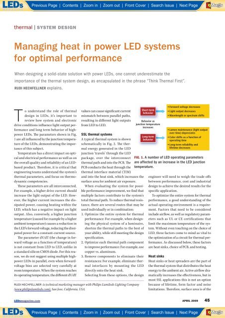
Previous Page | Contents | <strong>Zoom</strong> in | <strong>Zoom</strong> out | Front Cover | Search Issue | Next PageABE FMaGSthermal | SYSTEM DESIGNManaging heat in power LED systemsfor optimal performanceWhen designing a solid-state solution with power LEDs, one cannot underestimate theimportance of the thermal system design, as encapsulated in the phrase “Think Thermal First”.RUDI HECHFELLNER explains.To understand the role of thermaldesign in LEDs, it’s important toreview how system and electronicdrive conditions influence light output performanceand long term behavior of highpowerLEDs. The parameters shown in Fig.1 are all influenced by the junction temperatureof the LEDs, demonstrating the importanceof this subject.Temperature has a direct impact on opticaland electrical performance as well as onthe overall quality and reliability of an LEDbasedproduct. Therefore, it is critical thatengineering teams understand the system’sthermal parameters, and focus on thermodynamiccompetencies.These parameters are all interconnected.For example, a higher drive current shouldincrease the light output of the LED. However,the higher current increases the dissipatedpower, causing heating within theLED, which has a negative impact on lightoutput. Also, conversely, a higher junctiontemperature (caused for example by a higherambient temperature) causes a reduction inthe LED’s forward voltage, reducing the dissipatedpower for a constant-current source.The parameter dV/dT (the change in forwardvoltage as a function of temperature)is not constant from LED to LED, unlike ina standard silicon CMOS diode. For this reason,we do not suggest using multiple highpowerLEDs in parallel, even when forwardvoltagebins are selected very carefully atroom temperature. When the system reachesits operating temperature, the different dV/dTvalues can cause significant currentmismatch between parallel paths,resulting in different light outputsfrom LED to LED.SSL thermal systemsA typical thermal system is shownschematically in Fig. 2. The thermalenergy generated in the LEDjunction ‘travels’ through the LEDpackage, over the interconnectthermal path and into the PCB. ThePCB conducts the heat through thethermal interface material (TIM)and into the heat sink, which increases thesurface area for ambient air exposure.When evaluating the system for possibleperformance improvement, we find thatmultiple factors contribute to the system’stotal thermal path. To reduce thermal resistance,there are several routes that may beused individually or in combination:1. Optimize the entire system for thermalperformance: For example, when designingthe physical system of a luminaire,shorten the thermal paths to the best ofyour ability, while still meeting the designspecification.2. Optimize each thermal path componentto improve performance: For example, usecopper vs. aluminum.3. Remove components to eliminate theirresistances: For example, eliminate thermalinterfaces by mounting the LEDdirectly onto the heat sink.Selecting from these options, the designRUDI HECHFELLNER is technical marketing manager with Philips Lumileds Lighting Company(www.philipslumileds.com), San Jose, California, USA.Short-termbehaviorBehavior asjunction temperatureincreasesLong-termbehavior operating time FIG. 1. A number of LED operating parametersare affected by an increase in the LED junctiontemperature.engineer will need to weigh the trade-offsbetween performance, cost and industrialdesign to achieve the desired results for thespecific application.To optimize the entire system for thermalperformance, a good understanding of theactual operating environment is a requirement.Factors that need to be consideredinclude airflow, as well as regulatory parameterssuch as UL or CE certifications thatlimit the maximum temperature of the system.Without even touching on the choice ofLED, three factors come to mind as vital tothe optimization of a circuit for thermal performance.As discussed below, these factorsare heat sinks, choice of PCB, and testing.Heat sinksHeat sinks or heat spreaders are the part ofthe thermal system that distributes the heatenergy to the ambient air. Active airflow dramaticallyincreases the effectiveness, but inmost SSL applications this is not an optionbecause of lifetime, form factor and noiselimitations. Therefore, surface area is of theLEDsmagazine.com APRIL 2009 45Previous Page | Contents | <strong>Zoom</strong> in | <strong>Zoom</strong> out | Front Cover | Search Issue | Next PageABE FMaGS