MINI-CIRCUITS / AVANTEK MONOLITHIC AMPLIFIERS ( DC TO ...
MINI-CIRCUITS / AVANTEK MONOLITHIC AMPLIFIERS ( DC TO ...
MINI-CIRCUITS / AVANTEK MONOLITHIC AMPLIFIERS ( DC TO ...
- No tags were found...

Create successful ePaper yourself
Turn your PDF publications into a flip-book with our unique Google optimized e-Paper software.
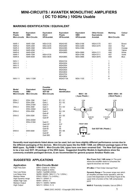
<strong>MINI</strong>-<strong>CIRCUITS</strong> / <strong>AVANTEK</strong> <strong>MONOLITHIC</strong> <strong>AMPLIFIERS</strong>( <strong>DC</strong> <strong>TO</strong> 8GHz ) 10GHz UsableMARKING IDENTIFICATION / EQUIVALENTModel Equivalent Equivalent Equivalent Equivalent Other Known Marking ColourPlastic SMD 83mil Plastic SMD Equivalents DotMini-circuits Mini-Circuits HP/Avantek HP/Avantek HP/Avantek Avantek Mini-CircuitsMAR-1 MAR-1SM MSA-0135 MSA0185 MSA-0186 MSA-0170 A01 BrownMAR-2 MAR-2SM MSA-0235 MSA0285 MSA-0286 MSA-0270 A02 RedMAR-3 MAR-3SM MSA-0335 MSA0385 MSA-0386 A03 OrangeMAR-4 MAR-4SM - MSA0485 - A04 YellowMAR-6 MAR-6SM - MSA0685 MSA-0686 MSA-2111 A06 WhiteMAR-7 MAR-7SM MSA-0735 MSA-0786 MSA-0711 A07 VioletMAR-8 MAR-8SM MSA-0835 MSA0885 MSA-0886 MSA-0870 A08 BlueMAV-1 - MSA0104 - 1 -MAV-2 - MSA0204 - 2 -MAV-3 - MSA0304 - 3 -MAV-4 - MSA0404 - 4 -MSA0504 - 5 -MSA0604 - 6 -MSA0704 - 7 -MSA0804 - 8 -MAV-11 MAV-11SM - MSA01104 MSA-1105 - A -PossibleModel Equivalent Equivalent MarkingPlastic SMD SOT-89 IdentificationMini-Circuits Mini-Circuits Mini-Circuits MAV / -04 MAR / ERA / -85( 4-pac Plastic ) ( 85mil Plastic )ERA-1 ERA-1SM Gali-1 E1 / 01GNDERA-2 ERA-2SM Gali-2 E2 / 02- ERA-21SM Gali-21 21ERA-3 ERA-3SM Gali-3 E3 / 03- ERA-33SM Gali-33 33INOUTERA-4 ERA-4SM Gali-4 E4 / 04- - Gali-4F 4FERA-5 ERA-5SM Gali-5 E5 / 05RAISE<strong>DC</strong>OLOUR- - Gali-5F 5FDOTDOT- ERA-50SM - 50- ERA-51SM Gali-51 51- - Gali-51F 51FFRONT VIEW- - Gali-52 52- - Gali-55 55 Gali SOT-89 ( Plastic )ERA-6 ERA-6SM Gali-6 E6 / 0601- - Gali-6F 6FIN- - Gali-S66 66GNDOUTGNDGenerally most equivalents listed above can be used, but can have slightly different performance curves due tothe different packaging of the devices. Mini-Circuits types like the RAM / VAM, are different package types of theMAR types. Eg RAM-1 = MAR-1. Mini-Circuits GAL types have now been renamed Gali. The New Gali types seemto be a low cost SOT- 89 package of the ERA types. Suggested Amplifier Models & Applications show thecommonly available packaged devices, & are recommended for general purpose Amateur Radio use.SUGGESTED APPLICATIONSApplicationMini-Circuits ModelHigh Freq GainERA1 Usable to 10GHzERA2 Usable to 6GHzVery Low NoiseGali52 / GaliS66 (2GHz)Low Noise Amp MAR6 / MAR8 / MAV11 ( To 1.2GHz )Medium Noise ERA3 / ERA5 ( To 2.4GHz )High Dynamic range MAV11 / ERA4 / 5Stable High Gain MAR1 / ERA3 / 5Medium OutputMAV11 / MAR3 / MAR4High Output MAV11 / ERA4 / 5 / 6Max Power Out ( 1dB comp ) = The pointwhere the amplifier starts to compress thesignal & becomes non linearIP3 dBm = Third Order Intercept PointDynamic Range = The power range over whichan amplifier provides linear operation, with theLower limit dependant on the Noise Figure & theupper limit a function of the 1dB compressionpointMAR-8 Potentially Unstable, Use an ERA-3MMIC.DOC 24/2/02 ©Copyright 2002 Mini-Kits 1
<strong>MINI</strong>-<strong>CIRCUITS</strong> AMPLIFIER GAIN / OUTPUT / NOISE FIGURE SELECTIONGain Typical dB at Freq GHz Maximum Power Out Noise IP3 dBm1dB Comp @ 1GHz Figure @ 1GHzModel 0.1 0.5 1 2 3 4 6 8MAR-1 18.5 17.5 15.5 - - - - - +1.5dBm 5.5 +14.0MAR-2 12.5 12.3 12.0 11.0 - - - - +4.5dBm 6.5 +17.0MAR-3 12.5 12.2 12.0 11.5 - - - - +10.0dBm 6.0 +23.0MAR-4 8.3 8.2 8.0 - - - - - +12.5dBm 6.5 +25.5MAR-6 20.0 18.5 16.0 11.0 - - - - +2.0dBm 3.0 +14.5MAR-7 13.5 13.1 12.5 11.0 - - - - +5.5dBm 5.0 +19.0MAR-8 32.5 28.0 22.5 - - - - - +12.5dBm 3.3 +27.0MAV-11 12.7 12.0 10.5 - - - - - +17.5dBm 3.6 +30.0ERA-1 - - - 11.6 11.2 - 10.5 9.6 +13.0dBm (2GHz) 7.0 (2GHz) +26.0ERA-2 16.0 - - 14.9 13.9 - 11.8 - +14.0dBm (2GHz) 6.0 (2GHz) +27.0ERA-3 22.2 - - 20.2 18.2 - - - +11.0dBm (2GHz) 4.5 (2GHz) +23.0ERA-4 13.8 - 14.0 13.9 13.9 13.4 - - +19.1dBm 5.2 +36.0ERA-5 20.4 - 20.0 19.0 17.6 15.8 - - +19.6dBm 4.0 +36.0ERA-6 11.1 - 11.1 11.3 11.5 11.3 - - +18.5dBm 8.4 +36.5Gali-1 12.7 - 12.5 11.8 11.3 10.5 10.5 11.0 +12.2dBm (2GHz) 4.5 (2GHz) +27.0Gali-21 14.3 - 13.9 13.1 12.4 11.5 11.9 12.4 +12.6dBm (2GHz) 4.0 (2GHz) +27.0Gali-2 16.2 - 15.8 14.8 13.7 12.7 13.2 15.1 +12.9dBm (2GHz) 4.6 (2GHz) +27.0Gali-33 19.3 - 18.7 17.5 16.3 15.5 15.8 - +13.4dBm (2GHz) 3.9 (2GHz) +28.0Gali-3 22.4 - 21.1 19.1 17.3 16.1 15.8 - +12.5dBm (2GHz) 3.5 (2GHz) +25.0Gali-6F 12.1 - 12.0 11.6 11.4 10.9 12.3 - +15.8dBm 4.5 +35.5Gali-4F 14.3 - 14.0 13.4 13.0 12.3 13.2 - +15.3dBm 4.0 +32.0Gali-51F 18.0 - 17.3 15.9 14.8 13.4 13.3 - +15.9dBm 3.5 +32.0Gali-5F 20.4 - 19.3 17.4 16.0 14.8 15.1 - +15.7dBm 3.5 +31.5Gali-55 21.9 - 20.6 18.5 17.0 15.5 15.7 - +15.0dBm (2GHz) 3.3 (2GHz) +28.5Gali-52 22.9 - 20.8 17.8 15.9 14.4 - - +15.5dBm 2.7 +32.0Gali-6 12.2 - 12.2 11.8 11.3 11.4 12.3 - +18.2dBm 4.5 +35.5Gali-4 14.4 - 14.1 13.5 12.9 12.5 13.1 - +17.5dBm 4.0 +34.0Gali-51 18.1 - 17.5 16.1 14.7 13.7 13.4 - +18.0dBm 3.5 +35.0Gali-5 20.6 - 19.4 17.5 16.0 14.9 15.1 - +18.0dBm 3.5 +35.0Gali-S66 22.0 - 20.3 17.3 15.5 - - - +2.8dBm 2.7 (2GHz) +18.0BIAS CONFIGURATIONSUGGESTED RESIS<strong>TO</strong>R BIAS VALUESModel ImA Vd +5Vcc +9Vcc +12Vcc +13.8Vcc P / Watts Resistor (+12Vcc)MAR-1 17 5.00 - 220ohm 470ohm 560ohm 0.119WMAR-2 25 5.00 - 150ohm 270ohm 390ohm 0.175WMAR-3 35 5.00 - 120ohm 200ohm 270ohm 0.245WMAR-4 50 5.25 - 75ohm 150ohm 180ohm 0.338WMAR-6 16 3.50 100ohm 390ohm 560ohm 680ohm 0.136WMAR-7 22 4.00 47ohm 220ohm 390ohm 470ohm 0.176WMAR-8 36 7.80 - 33ohm 120ohm 180ohm 0.151WMAV-11 60 5.50 - 56ohm 120ohm 150ohm 0.390WERA-1 40 3.60 35ohm 130ohm 220ohm 255ohm 0.336WERA-2 40 3.60 35ohm 130ohm 220ohm 255ohm 0.336WERA-3 35 3.50 43ohm 157ohm 243ohm 300ohm 0.298WERA-4 65 5.00 - 62ohm 109ohm 130ohm 0.462WERA-5 65 4.90 - 62ohm 109hm 130ohm 0.462WERA-6 70 5.50 - 50ohm 93ohm 136ohm 0.455WGali-1 40 3.40 40ohm 140ohm 220ohm 260ohm 0.344WGali-2 40 3.50 37.5ohm 137ohm 215ohm 260ohm 0.344WGali-3 35 3.30 47ohm 162ohm 249ohm 300ohm 0.305WGali-4 65 4.60 - 68ohm 110ohm 143ohm 0.480WGali-5 65 4.40 - 68ohm 110ohm 143ohm 0.480WGail-6 70 5.00 - 56ohm 100ohm 120ohm 0.490WMMIC.DOC 24/2/02 ©Copyright 2002 Mini-Kits 2
TYPICAL BIASING CONFIGURATIONMSA = Monolithic Silicon AmpMMIC= Monolithic MicrowaveIntegrated CircuitR bias = Vcc - VdI biasVcc = The supply VoltageVd = The Device VoltageI bias = The Bias Current In mA ( ImA )P Watts = V x IP Watts = Power Rating Of R biasV = Volts across R biasI = Current Through R biasC block: Determines the low frequency cut off of the amplifier circuit. The Capacitors value is chosen to suit the frequency that the amplifiercircuit is going to be used for. On frequencies above 2.4GHz ATC Porcelain Chip Capacitors are normally used for low loss. On 10GHz &higher, ¼ wave stripline couplers are commonly used for low loss.100MHz ( 1nF ) 400MHz ( 100pF ) 1.2GHz ( 10pF ) 2.5GHz ( 5pF ) 10GHz ( 1 - 2pF )RFC (Optional): Is used to isolate the bias resistor so that it does not appear in parallel with the output load of the amplifier, degrading the outputmatch of the amplifier. The impedance of the choke at the lowest frequency of operation of the amplifier plus the value of the bias resistor shouldbe at least 500ohms100MHz ( 10uH choke )400MHz ( 3 turns 0.315mm TCW on a FB-43-101 ferrite bead )1.2GHz ( 100uH SMD choke or, 6 turns 0.315mm ECW 3mm dia closewound airspaced )2.4GHz ( 47uH SMD choke or 1/4wave Striplines on the PC board )>2.4GHz ( 1/4Wave Striplines on the PC Board )C bypass: A Capacitor should be used in conjunction with the RFC to present a low impedance path to ground for any signal that manages to getpast the RFC. The Capacitor should be connected at the junction of the R bias resistor & the RFC to ground. On 2.4GHz or higher ATCPorcelain Capacitors or similar may be required for effective bypassing.100MHz ( 1nF ) 400MHz ( 100pF ) 1.2GHz ( 10pF ) > 2.4GHz 5 to 10pF ATC Chip Capacitor& or a Microstrip Radial Line StubPowersupply Bypassing: Suitable Capacitors should be used on the Vcc rail to effectively bypass low & high frequencies.Suggested Values 1uF Tantalum 0.1uF 1nF ( Use all in parallel )This Data was assembled from a number of different sources including the Mini-Circuits & HewlettPackard WEB sites. It is assumed to be reasonably accurate, & is intended as a quick reference guidefor Engineers & Experimenters. For more detailed Data please refer to the Manufacturers WEB sites.This Data may be updated at any time due to changes from Manufactures, or errors. OtherManufacturers producing similar Products have not been added to this Data as their products arecurrently not readily available for Experimenters to buy.Mini-Circuits Products are available in Australia from www.minikits.com.auMMIC.DOC 24/2/02 ©Copyright 2002 Mini-Kits 3