

XTC PROPORTIONAL SWITCHBOX CONTROLS - McConnel
XTC PROPORTIONAL SWITCHBOX CONTROLS - McConnel
XTC PROPORTIONAL SWITCHBOX CONTROLS - McConnel
- No tags were found...

You also want an ePaper? Increase the reach of your titles
YUMPU automatically turns print PDFs into web optimized ePapers that Google loves.
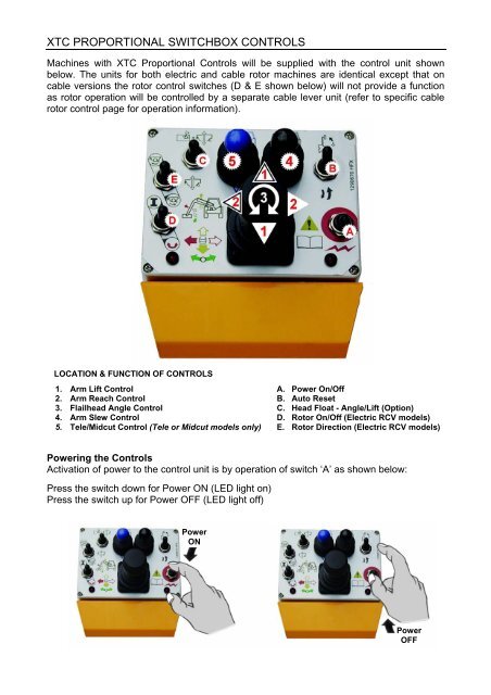
<strong>XTC</strong> <strong>PROPORTIONAL</strong> <strong>SWITCHBOX</strong> <strong>CONTROLS</strong>Machines with <strong>XTC</strong> Proportional Controls will be supplied with the control unit shownbelow. The units for both electric and cable rotor machines are identical except that oncable versions the rotor control switches (D & E shown below) will not provide a functionas rotor operation will be controlled by a separate cable lever unit (refer to specific cablerotor control page for operation information).LOCATION & FUNCTION OF <strong>CONTROLS</strong>1. Arm Lift Control2. Arm Reach Control3. Flailhead Angle Control4. Arm Slew Control5. Tele/Midcut Control (Tele or Midcut models only)A. Power On/OffB. Auto ResetC. Head Float - Angle/Lift (Option)D. Rotor On/Off (Electric RCV models)E. Rotor Direction (Electric RCV models)Powering the ControlsActivation of power to the control unit is by operation of switch ‘A’ as shown below:Press the switch down for Power ON (LED light on)Press the switch up for Power OFF (LED light off)PowerONPowerOFF
ARM OPERATIONAutoResetTele or Midcut Models only
HEAD FLOAT OPERATION (Angle Float standard / Lift Float optional)Angle Float OFFLift Float OFFAngle Float OFFLift Float ONAngle Float ONLift Float ONROTOR OPERATION – Electric Rotor Control Models onlyNOTE: The following section relates to machines with Electric Rotor Control only – for Cable RotorControl models refer to the cable rotor control section.Selection of Rotor Cutting DirectionUphill CuttingDownhill Cutting
Switching the Rotor OnFor safety reasons, to prevent accidental starting of the rotor, the ‘Rotor On’ switch cannotbe activated in a single operation or without first selecting the direction of cut – theprocedure for starting the rotor is as follows:Select the required cutting direction - the Rotor On/Off Switch (D) must then be switchedupwards and held in position for a minimum of 8 seconds before switching it into the fullydown ‘on’ position where it will remain until it is switched off. When the switch is moved tothe down position the red LED light below the switch will be lit to signify the rotor is on – ifthe LED does not light the switch was not held in its up position for long enough and therotor will not have started, repeat the process again holding the switch upwards for alonger period.Rotor StartSwitching the Rotor OffStopping the rotor is performed by switching either the Rotor Power Switch (D) or theRotor Direction Switch (E) to the central (off) position – the red LED light will go out tosignify the rotor has been switched off.Rotor StopCAUTION: When the rotor is switched off it will continue to ‘freewheel’ under its ownmomentum for up to 40 seconds before finally coming to a standstill – do not leave thetractor cab or attempt to approach the flailhead until the rotor has stopped turningcompletely.Alternative Rotor Stop
CABLE ROTOR CONTROLOn cable rotor control machines the rotor is operated by the lever shown below – from theupright ‘off’ position pushing the lever forward switches the rotor on for downhill cutting andpulling the lever backwards switches the rotor on for uphill cutting. The small pivot lockinglever mounted on the side of the control assembly rotates through 180° to lock the rotor ina specific cutting direction – this is a safety feature to avoid changes of rotor directionwithout first stopping the rotor. To change the direction of cut the rotor lever must beplaced in the upright ‘off’ position; when the rotor has stopped rotating completely the pivotlocking lever can be turned to the opposing position allowing the control lever to beoperated for opposite cutting direction.On some cable operated machines the rotor control lever will be assembled as part of themain bank of controls, whereas on others and all electric models it will be supplied as a‘standalone’ unit with its own mounting bracket.UPHILL CUTTINGLockDOWNHILL CUTTINGLockCAUTION: Ensure the rotor has stopped turning completely before attempting to changedirection - When switched off a rotor can continue to ‘freewheel’ under its own momentumfor up to 40 seconds before stopping.


