Instruction Manual book - Pichler
Instruction Manual book - Pichler
Instruction Manual book - Pichler
- No tags were found...

Create successful ePaper yourself
Turn your PDF publications into a flip-book with our unique Google optimized e-Paper software.
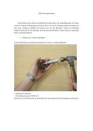
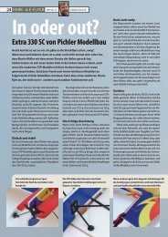
EDGE 540 V3-30cc - Item code: BH94 .<strong>Instruction</strong> <strong>Manual</strong>Secure.Repeat the procedure for the other winghalf.INSTALLING THE AILERON CONTROL HORN 1.3 x 50 mm. M2 lock nut.Install aileron control horn as sameas picture below.Elevatorcontrol horn1Repeat the procedure for the other winghalf.INSTALLING THE AILERONLINKAGES 1.Installing the aileron linkages as picturesbelow.70 mm3x12 mm.Attach the clevis to the outer hole in the controlhorn.5
EDGE 540 V3-30cc - Item code: BH94 .<strong>Instruction</strong> <strong>Manual</strong>Secure.2.INSTALLING THE AILERON SERVO- 2.ElectricwaythreadSecure.Secure.C/A glue.INSTALLING THE AILERON CONTROL HORN 2.3 x 50 mm. M2 lock nut.C/A glue.6
EDGE 540 V3-30cc - Item code: BH94 .<strong>Instruction</strong> <strong>Manual</strong>Secure.C/A glue.Elevatorcontrol horn 2C/A glue.INSTALLING THE AILERONLINKAGES 2.Installing the aileron linkages as picturesbelow.3x12 mm.70 mmRepeat the procedure for the other winghalf.INSTALLING THE ENGINE MOUNT.See pictures below:Secure.7
EDGE 540 V3-30cc - Item code: BH94 .<strong>Instruction</strong> <strong>Manual</strong>When the stopper assembly is installed in thetank, the top of the vent tube should rest justbelow the top surface of the tank. It should nottouch the top of the tank.Drill 8mmhole.Vent tubeFuel pick- up tubeFUEL TANK.INSTALLING THE STOPPER ASSEMBLY 1) The stopper has been pre-assembledat the factory. 2) Using a modeling knife, cut one lengthof silicon fuel line (the length of silicon fuel lineis calculated by how the weighted clunk shouldrest about 8mm away from the rear of the tankand move freely inside the tank). Connect oneend of the line to the weighted clunk and theother end to the nylon pick up tube in the stopper. 3) Carefully bend the second nylon tubeup at a 45 degree angle (using a cigarettelighter). This tube will be the vent tube to themuffler. 4) Carefully bend the third nylon tube downat a 45 degree angle (using a cigarette lighter).This tube will be vent tube to the fueling valve.Fuel fill tube 5) Test fit the stopper assembly into thetank. It may be necessary to remove some ofthe flashing around the tank opening usinga modeling knife. If flashing is present, makesure none of it falls into the tank. 6) When satisfied with the alignment ofthe stopper assembly tighten the 3mm x 20mmmachine screw until the rubber stopper expandsand seals the tank opening. Do not overtighten the assembly as this could cause thetank to split. 7) Using a modeling knife, cut 3 lengths offuel line 150mm long. Connect 2 lines to the 2vent tubes and 1 line to the fuel pickup tube inthe stopper. 8) Feed three lines through the fuel tankcompartment and through the pre-drilled holein the firewall. Pull the lines out from behindthe engine, while guiding the fuel tank intoplace. Push the fuel tank as far forward aspossible, the front of the tank should just abouttouch the back of the firewall.Blow through one of the lines to ensurethe fuel lines have not become kinked insidethe fuel tank compartment. Air should flowthrough easily.8
EDGE 540 V3-30cc - Item code: BH94 .<strong>Instruction</strong> <strong>Manual</strong> 9) To secure the fuel tank in place, apply abead of silicon sealer to the forward area ofthe tank, where it exits the fuselage behind theengine mounting box and to the rear of the tankat the forward bulkhead.Do not secure the tank into place permanentlyuntil after balancing the airplane. Youmay need to remove the tank to mount thebattery in the fuel tank compartmentSecure.INSTALLING THE ENGINE-THROTTLE.4x70mmFuel tankSecure.9
EDGE 540 V3-30cc - Item code: BH94 .<strong>Instruction</strong> <strong>Manual</strong>INSTALLING THE THROTTLE - CABLE. 1. Install one adjustable metal connectorthrough the third hole out from the center ofone servo arm, enlarge the hole in the servoarm using a 2mm drill bit to accommodate theservo connector. Remove the excess materialfrom the arm.After installing the adjustable metal connectorapply a small drop of thin C/A tothe bottom nut. This will prevent the connectorfrom loosening during flight.Throttle servoThrottle -cableThrottle - cableLeft side.10
EDGE 540 V3-30cc - Item code: BH94 .<strong>Instruction</strong> <strong>Manual</strong>Secure.Right side. 2) Using the hardware provided, mountthe main landing gear to the fuselage.MAIN GEAR INSTALATION.PARTS REQUIRED 1) Assemble and mounting the wheel pantsas shown in the following pictures.6x 20mmCut.Remove thecoveringLandinggear.11
EDGE 540 V3-30cc - Item code: BH94 .<strong>Instruction</strong> <strong>Manual</strong>Drill 8mmhole.Secure.Secure.COWLING. 1. Slide the fiberglass cowl over the engineand line up the back edge of the cowl withthe marks you made on the fuselage.Top side12
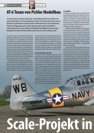
EDGE 540 V3-30cc - Item code: BH94 . 2. While keeping the back edge of thecowl flush with the marks, align the front ofthe cowl with the crankshaft of the engine. Thefront of the cowl should be positioned so thecrankshaft is in nearly the middle of the cowlopening. Hold the cowl firmly in place usingpieces of masking tape. 3. Slide the cowl back over the engineand secure it in place using four wood screws. 4. Install the muffler and muffler extensiononto the engine and make the cutout in thecowl for muffler clearance. Connect the fueland pressure lines to the carburetor, mufflerand fuel filler valve.<strong>Instruction</strong> <strong>Manual</strong>3 x 12mmMachine screw.Left side.Trim andcutBottom side.Bottom side.Mark line.13
EDGE 540 V3-30cc - Item code: BH94 .<strong>Instruction</strong> <strong>Manual</strong>Remove thecoveringBottom side. 3) A drop of C/A glue on the wheel collarscrews will help keep them from coming loseduring operation.Front viewEpoxy glue.INSTALLING THE SPINNER.Install the spinner backplate, propeller andspinner cone. The spinner cone is held inplace using two 3mm x 12mm wood screws.C/A glue.Secure14
EDGE 540 V3-30cc - Item code: BH94 .<strong>Instruction</strong> <strong>Manual</strong>Secure.HORIZONTAL STABILIZER.Horizontal stabilizer installationSee picture below.Top side. Draw a center line onto the horizontal stabilizer.Then put the horizontal into the fuselarge.INSTALLING THE ELEVATORSERVOS.Center line. 1. Install the rubber grommets and brasscollets into the elevator servo. Test fit theservo into the servo tray.Check to mark sure the wing and stabilizerare paralell. If they are not, lightly sandthe opening in the fuselage for the stabilizeruntil the stabilizer is paralell to the wing. 2. Mount the servo to the tray using themounting screws provided with your radiosystem.15
EDGE 540 V3-30cc - Item code: BH94 .<strong>Instruction</strong> <strong>Manual</strong>VERTICAL INSTALLATION.Vertical stabilizer installationSee picture below. 4. Now, remove the rudder and using amodeling knife, carefully cut just inside themarked lines and remove the film of the rudder.Just as you did with the horizontal stabilizer,make sure you only press hard enoughto cut the film, not the balsa rudder. Also carefully remove the covering fromthe horizontal fin as below the lines whichyou drew as same picture below.Removecovering.Removecovering. 1. Put the rudder into the fuselage as sameas picture below. 2. Mark the shape of the vertical on theleft and right side of the rudder on to the horizontalstabilizer using a felt-tip pen. 5) When you are sure that everything is aaligned correctly, mix up a generous amountof 30 minute epoxy. Apply a thin layer to theslot in the mounting platform and to the verticalstabilizer mounting area. Apply epoxy tothe lower rudder hinge. Set the stabilizer inplace and re-align. Double check all of yourmeasurements once more before the epoxycures. Remove any excess epoxy using apaper towel and rubbing alcohol and hold thestabilizer in place with T-pins or masking tape.Allow the epoxy to fully cure before proceeding.Mark line.HorizontalStabilizer.90ºVerticalStabilizer.16
EDGE 540 V3-30cc - Item code: BH94 .<strong>Instruction</strong> <strong>Manual</strong>SecureEpoxy glue.Epoxy glue.4 x 50mmC/A glue.Secure.4x 50mmELEVATOR CONTROL HORN INSTALLA-TION.SecureElevator control horn install as same as theway of aileron control horn. Please see picturesbelow.3 x 40 mm.M2 lock nut.17
EDGE 540 V3-30cc - Item code: BH94 .<strong>Instruction</strong> <strong>Manual</strong>ELEVATOR PUSHROD INSTALLATION.Epoxy glue.Elevator pushrod install as same as the wayof aileron pushrod.125 mm3 x 12 mmSecure.Secure.C/A glue.Elevatorcontrol horn.C/A glue.18
EDGE 540 V3-30cc - Item code: BH94 .<strong>Instruction</strong> <strong>Manual</strong>ElevatorpushrodElevatorpushrodBottom side.RUDDER SERVO INSTALLATION.AluminiumRudder push-pullcable.Rudder Servo.19
EDGE 540 V3-30cc - Item code: BH94 .<strong>Instruction</strong> <strong>Manual</strong>C/A glue.Bottom side.RUDDER CONTROL HORN INSTALLA-TION.Rudder control horn install as same as theway of aileron control horn. Please see picturesbelow.3 x 80 mmControl horn of Rudder.Ruddercontrol horn.RUDDER PUSHROD INSTALLATION. 1. Rudder pushrod install as same asthe way of aileron control horn. 2. Rudder push - pull system install assame as picture below.Bottom side.3 x 12mmC/A glue.Secure.20
EDGE 540 V3-30cc - Item code: BH94 .<strong>Instruction</strong> <strong>Manual</strong>Bottom sideRuddercable.Ruddercable.ElevatorpushrodElevatorpushrodRuddercable.Ruddercable.Plastic parts of rudderpushrod.3 x 12mmCut.Secure.C/A glue.21
EDGE 540 V3-30cc - Item code: BH94 .<strong>Instruction</strong> <strong>Manual</strong>Secure.Mark line.Removecovering.Rudder push-pullcable.Rudder plastic light.C/A Epoxy.Remove thecovering22
EDGE 540 V3-30cc - Item code: BH94 .<strong>Instruction</strong> <strong>Manual</strong>C/A glue.Secure.MOUNTING THE TAIL WHEELBRACKET.Secure.3x12mm3x15mmDrill a hole4mm diameter.Bottom side.23
EDGE 540 V3-30cc - Item code: BH94 .<strong>Instruction</strong> <strong>Manual</strong>INSTALLING THE SWITCH. 1. Cut out the switch hole using a modelingknife. Use a 2mm drill bit and drill out the twomounting holes through the fuselage side.Tie wrap. 2. Secure the switch in place using thetwo machine screws provided with the radiosystem.SwitchBATTERY.SwitchSwitchTie wrap.INSTALLING THE RECEIVER AND BATTERY. 1. Plug the servo leads and the switchlead into the receiver. You may want to plugan aileron extension into the receiver to makeplugging in the aileron servo lead easierwhen you are installing the wing . Plug thebattery pack lead into the switch. 2. Wrap the receiver and battery pack inthe protective foam to protect them from vibration.Use a rubber band or masking tape tohold the foam in place. 3. Position the battery pack and receiverbehind the fuel tank. Use two tie wraps to holdthe battery and receiver securely in place aspictures belowDo not permanently secure the receiverand battery until after balancing themodel.Tie wrap.RECEIVER.WING ATTACHMENT.Locate the aluminium wing dihedral brace.24
EDGE 540 V3-30cc - Item code: BH94 .<strong>Instruction</strong> <strong>Manual</strong>Drill 3mmhole.Secure.RECEIVER.Left wing.See picture wing attach to fuselage.Installing the fuselage hatch as same as picturebelow.Wing bolt.Left wingWing bolt.RECEIVER.SwitchDrill 3mmhole.4 x 35mm25
EDGE 540 V3-30cc - Item code: BH94 .<strong>Instruction</strong> <strong>Manual</strong>Secure.Accurately mark the balance point on the topof the wing on both sides of the fuselage. Thebalance point is located 88mm back from theleading edge. This is the balance point atwhich your model should balance for your firstflights. Later, you may wish to experiment byshifting the balance up to 10mm forward orback to change the flying characteristics.Moving the balance forward may improve thesmoothness and arrow- like tracking, but itmay then require more speed for take offand make it more difficult to slow down forlanding. Moving the balance aft makes themodel more agile with a lighter and snappier”feel”. In any case, please start at the locationwe recommend .Lift the model. If the tail drops when youlift, the model is “tail heavy” and you mustadd weigh* to the nose. If the nose drops, itis “nose heavy” and you must add weight* tothe tail to balance.With the wing attached to the fuselage, allparts of the model installed ( ready to fly), andempty fuel tanks, hold the model at themarked balance point with the stabilizer level.Top side*If possible, first attempt to balance the modelby changing the position of the receiver batteryand receiver. If you are unable to obtaingood balance by doing so, then it will be necessaryto add weight to the nose or tail toachieve the proper balance point.BALANCING. 1) It is critical that your airplane be balancedcorrectly. Improper balance will causeyour plane to lose control and crash.THE CENTER OF GRAVITY IS LOCATED88 MM BACK FROM THE LEADING EDGEOF THE WING. 2) Mount the wing to the fuselage. Using acouple of pieces of masking tape, place themon the top side of the wing 88mm back fromthe leading edge, at the fuselage sides. 3. Turn the airplane upside down. Placeyour fingers on the masking tape and carefullylift the plane .CONTROL THROWS. 1) We highly recommend setting up aplane using the control throws listed. 2) The control throws should be measuredat the widest point of each control surface. 3) Check to be sure the control surfacesmove in the correct directions.26
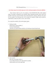
EDGE 540 V3-30cc - Item code: BH94 .<strong>Instruction</strong> <strong>Manual</strong>Ailerons : 25mm up 25mm downElevator : 25mm up 25mm downRudder : 40mm right 40mm leftAileron Control252525254040PRE-FLIGHT CHECK. 1) Completely charge your transmitter andreceiver batteries before your first day of flying. 2) Check every bolt and every glue joint inyour plane to ensure that everything is tightand well bonded. 3) Double check the balance of theairplane. 4) Check the control surface. 5) Check the receiver antenna . It shouldbe fully extended and not coiled up inside thefuselage. 6) Properly balance the propeller.We wish you many safe and enjoyableflights with your EDGE 540-V3 30CC.27