Combo D.pdf - Positronic Industries Inc
Combo D.pdf - Positronic Industries Inc
Combo D.pdf - Positronic Industries Inc
- No tags were found...

Create successful ePaper yourself
Turn your PDF publications into a flip-book with our unique Google optimized e-Paper software.
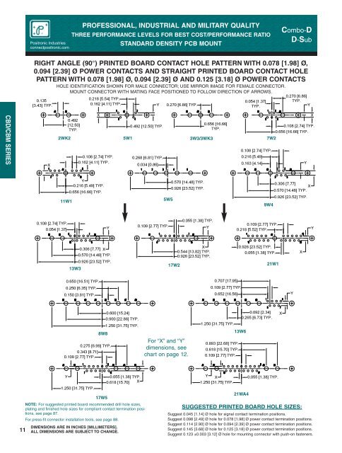
<strong>Positronic</strong> <strong>Industries</strong>connectpositronic.comPROFESSIONAL, INDUSTRIAL AND MILITARY QUALITYTHREE PERFORMANCE LEVELS FOR BEST COST/PERFORMANCE RATIOSTANDARD DENSITY PCB MOUNT<strong>Combo</strong>-DD-SubRIGHT ANGLE (90°) PRINTED BOARD CONTACT HOLE PATTERN WITH 0.078 [1.98] Ø,0.094 [2.39] Ø POWER CONTACTS AND STRAIGHT PRINTED BOARD CONTACT HOLEPATTERN WITH 0.078 [1.98] Ø, 0.094 [2.39] Ø AND 0.125 [3.18] Ø POWER CONTACTSHOLE IDENTIFICATION SHOWN FOR MALE CONNECTOR; USE MIRROR IMAGE FOR FEMALE CONNECTOR.0.135[3.43] TYP.MOUNT CONNECTOR WITH MATING FACE POSITIONED TO FOLLOW DIRECTION OF ARROWS.0.218 [5.54] TYP.0.162 [4.11] TYP.Y0.270 [6.86] TYP.0.054 [1.37]TYP.0.270 [6.86]TYP.YCBD/CBM SERIESX2WK20.492[12.50]TYP.X0.108 [2.74] TYP.0.162 [4.11] TYP.0.492 [12.50] TYP.5W10.268 [6.81] TYP.0.034 [0.86]3W3/3WK30.656 [16.66]TYP.X0.108 [2.74] TYP.0.656 [16.66] TYP.7W20.108 [2.74] TYP.0.216 [5.49]0.163 [4.14]YY0.216 [5.49] TYP.0.656 [16.66] TYP.11W15W50.570 [14.48] TYP.0.926 [23.52] TYP.0.306 [7.77]X0.570 [14.48] TYP.0.926 [23.52] TYP.9W40.108 [2.74] TYP.0.054 [1.37]Y0.109 [2.77] TYP.0.055 [1.38] TYP.Y0.109 [2.77] TYP.0.218 [5.52] TYP.Y0.306 [7.77] X0.570 [14.48] TYP.0.926 [23.52] TYP.13W3X0.544 [13.82] TYP.0.926 [23.52] TYP.17W20.926 [23.52] TYP.0.055 [1.38] TYP.21W1X0.650 [16.51] TYP.0.250 [6.35] TYP.0.150 [3.81] TYP.0.707 [17.95]0.109 [2.77] TYP.0.652 [16.56]Y0.275 [6.99] TYP.0.343 [8.71]0.109 [2.77] TYP.8W80.600 [15.24]0.900 [22.86] TYP.1.250 [31.75] TYP.For “X” and “Y”dimensions, seechart on page 12.1.250 [31.75] TYP.0.893 [22.68] TYP.0.618 [15.70] TYP.0.109 [2.77] TYP.13W60.092 [2.34]0.265 [6.73] TYP.X11Y1.250 [31.75] TYP.DIMENSIONS ARE IN INCHES [MILLIMETERS].ALL DIMENSIONS ARE SUBJECT TO CHANGE.0.055 [1.38] TYP.0.618 [15.70] X17W5NOTE: For suggested printed board recommended drill hole sizes,plating and finished hole sizes for compliant contact termination positions,see page 87.For press-fit connector installation tools, see page 88.Y X1.250 [31.75] TYP.21WA40.055 [1.38] TYP.SUGGESTED PRINTED BOARD HOLE SIZES:Suggest 0.045 [1.14] Ø hole for signal contact termination positions.Suggest 0.098 [2.49] Ø hole for 0.078 [1.98] Ø power contact termination positions.Suggest 0.114 [2.90] Ø hole for 0.094 [2.39] Ø power contact termination positions.Suggest 0.145 [3.68] Ø hole for 0.125 [3.18] Ø power contact termination positions.Suggest 0.123 ±0.003 [3.12] Ø hole for mounting connector with push-on fasteners.