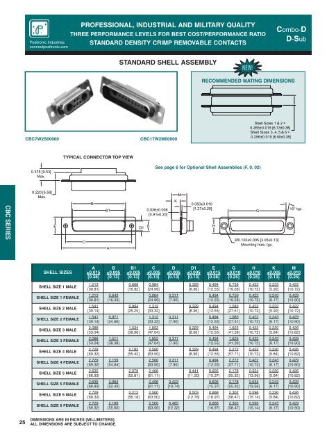
<strong>Positronic</strong> <strong>Industries</strong>connectpositronic.comPROFESSIONAL, INDUSTRIAL AND MILITARY QUALITYTHREE PERFORMANCE LEVELS FOR BEST COST/PERFORMANCE RATIOSTANDARD DENSITY CRIMP REMOVABLE CONTACTS<strong>Combo</strong>-DD-SubSTANDARD SHELL ASSEMBLYNEW!RECOMMENDED MATING DIMENSIONSCBC7W2S00000CBC17W2M00000Shell Sizes 1 & 2 =0.265±0.015 [6.73±0.38]Shell Sizes 3, 4, 5 & 6 =0.256±0.015 [6.50±0.38]TYPICAL CONNECTOR TOP VIEW0.375 [9.53]Max.See page 6 for Optional Shell Assemblies (F, 0, 02)CBC SERIES0.220 [5.59]Max.BE D1 DCB1A0.036±0.008[0.91±0.20]KM0.050±0.010[1.27±0.25]HGØ0.120±0.005 [3.05±0.13]Mounting hole, typ.10° typ.SHELL SIZESA±0.015[0.38]B±0.005[0.13]B1±0.005[0.13]C±0.005[0.13]D±0.005[0.13]D1±0.005[0.13]E±0.015[0.38]G±0.010[0.25]H±0.010[0.25]K±0.005[0.13]M±0.010[0.25]SHELL SIZE 1 MALE1.213[30.81]0.666[16.92]0.984[24.99]0.329[8.36]0.494[12.55]0.759[19.28]0.422[10.72]0.233[5.92]0.422[10.72]SHELL SIZE 1 FEMALE1.213[30.81]0.643[16.33]0.984[24.99]0.311[7.90]0.494[12.55]0.759[19.28]0.422[10.72]0.243[6.17]0.429[10.90]SHELL SIZE 2 MALE1.541[39.14]0.994[25.25]1.312[33.32]0.329[8.36]0.494[12.55]1.083[27.51]0.422[10.72]0.233[5.92]0.422[10.72]SHELL SIZE 2 FEMALE1.541[39.14]0.971[24.66]1.312[33.32]0.311[7.90]0.494[12.55]1.083[27.51]0.422[10.72]0.243[6.17]0.429[10.90]SHELL SIZE 3 MALE2.088[53.04]1.534[38.96]1.852[47.04]0.329[8.36]0.494[12.55]1.625[41.28]0.422[10.72]0.230[5.84]0.426[10.82]SHELL SIZE 3 FEMALE2.088[53.04]1.511[38.38]1.852[47.04]0.311[7.90]0.494[12.55]1.625[41.28]0.422[10.72]0.243[6.17]0.429[10.90]SHELL SIZE 4 MALE2.729[69.32]2.182[55.42]2.500[63.50]0.329[8.36]0.494[12.55]2.272[57.71]0.422[10.72]0.230[5.84]0.426[10.82]SHELL SIZE 4 FEMALE2.729[69.32]2.159[54.84]2.500[63.50]0.311[7.90]0.494[12.55]2.272[57.71]0.422[10.72]0.243[6.17]0.429[10.90]SHELL SIZE 5 MALE2.635[66.93]2.079[52.81]2.406[61.11]0.441[11.20]0.605[15.37]2.178[55.32]0.534[13.56]0.230[5.84]0.426[10.82]SHELL SIZE 5 FEMALE2.635[66.93]2.064[52.43]2.406[61.11]0.423[10.74]0.605[15.37]2.178[55.32]0.534[13.56]0.243[6.17]0.429[10.90]SHELL SIZE 6 MALE2.729[69.32]2.212[56.18]2.500[63.50]0.503[12.78]0.668[16.97]2.302[58.47]0.596[15.14]0.230[5.84]0.426[10.82]SHELL SIZE 6 FEMALE2.729[69.32]2.189[55.60]2.500[63.50]0.485[12.32]0.668[16.97]2.302[58.47]0.596[15.14]0.243[6.17]0.429[10.90]25DIMENSIONS ARE IN INCHES [MILLIMETERS].ALL DIMENSIONS ARE SUBJECT TO CHANGE.
P O S I T R O N I C I N D U S T R I E S<strong>Combo</strong>-DD-SubPROFESSIONAL, INDUSTRIAL AND MILITARY QUALITYTHREE PERFORMANCE LEVELS FOR BEST COST/PERFORMANCE RATIOSTANDARD DENSITY CRIMP REMOVABLE CONTACTS<strong>Positronic</strong> <strong>Industries</strong>connectpositronic.comORDERING INFORMATION - CODE NUMBERING SYSTEMSpecify Complete Connector By Selecting An Option From Step 1 Through 8STEPEXAMPLE1 2 3 4 5 6 7 8 9CBC 7W2 M 1 0 Z 0 0 /AA10-14STEP 1 - BASIC SERIESCBC SeriesSTEP 2 - CONNECTOR VARIANTSShell Size 15W1Shell Size 27W2, 11W1Shell Size 39W4, 13W3, 17W2, 21W1Shell Size 4* 1 13W6, 21WA4, 25W3, * 1 27W2Shell Size 524W7, 36W4, 43W2, 47W1Shell Size 646W4STEP 3 - CONNECTOR GENDERM - MaleS - Female - Industrial or Military LevelPosiBand Closed Entry Signal ContactsProfessional Level female open entry contacts areavailable and can be ordered separately, see page 73.STEP 4 - CONTACT TERMINATION TYPE0 – Connector ordered without contacts. Order signal,power, shielded, high voltage, air and thermocouplecontacts separately. See pages 68-80 for contactpart numbers.1 – Signal contacts, 20 AWG-24 AWG [0.5mm 2 -0.25mm 2 ].11 – Signal contacts, 20 AWG-24 AWG [0.5mm 2 -0.25mm 2 ] with MC/FC 4012D Power Contact.12 – Signal contacts, 20 AWG-24 AWG [0.5mm 2 -0.25mm 2 ] with MC/FC 4016D power contact.13 – Signal contacts, 20 AWG-24 AWG [0.5mm 2 -0.25mm 2 ] with MCC/FCC 4101D shielded contacts.14 – Signal contacts, 20 AWG-24 AWG [0.5mm 2 -0.25mm 2 ] with MCC/FCC 4102D shielded contacts.* 2 STEP 5 - MOUNTING STYLE0 – Mounting Hole, 0.120 [3.05] Ø02 – Mounting Hole, 0.154 [3.91] ØF – Float Mounts, UniversalS2 – Swaged Spacer, 4-40 Threads, 0.125 [3.18] LengthS5 – Swaged Locknut, 4-40 ThreadsRoHS• per EU Directive 2002/95/EC* 2 STEP 10 - SPECIAL OPTIONSFOR SPECIAL OPTIONS, SEESPECIAL OPTIONS APPENDIXON PAGE 89.STEP 9 - ENVIRONMENTALCOMPLIANCEOPTIONS/AA - Compliant per EU Directive2002/95/EC (RoHS)STEP 8 - SHELL OPTIONS0 – Zinc Plated, with Chromate Seal.* 4 S – Stainless Steel, passivated.X – Tin Plated.Z – Tin Plated and Dimpled (male connectors only)* 2 STEP 6 - HOODS0 – NoneH – Hood, Top Opening, Metal, shell sizes 2 through 5AN – Lightweight Aluminum Hood, nickel finish.AC – Lightweight Aluminum Hood, no finish.* 3 G – Hood, EMI/RFI, Metal, shell sizes 1 through 6Z – Hood, Top or Side Opening, robust extended height, plastic andcomposite, with rotating jackscrews, shell sizes 1 through 5•NOTE: If compliance to environmentallegislation is not required, this step will notbe used. Example: CBC7W2M10Z00* 2 STEP 7 - LOCKING AND POLARIZING SYSTEMS0 – None.V3 – Lock Tab, connector front panel mounted.V5 – Lock Tab, connector rear panel mounted.VL – Lock Lever, used with Hoods only.T – Fixed Female Jackscrews.T2 – Fixed Female Jackscrews.T6 – Fixed Male and Female Polarized Jackscrews.E – Rotating Male Jackscrews.E2 – Rotating Male Screw Locks.E3 – Rotating Male with Internal Hex for 3/32 Hex DrivesE6 – Rotating Male and Female Polarized Jackscrews.NOTE: Once you have made a connector selection, contactTechnical Sales if you would like to receive a drawing in DXF, PDFformat or a 3-dimensional IGES, STEP, or SOLIDWORKS file.CBC SERIESNOTES* 1 Connector variant 13W6 and 27W2 are currently available in femaleonly, contact Technical Sales for availability of male connector.* 2 For additional information on accessories listed in steps5, 6, 7 and 10, see Accessory Catalog.* 3 When using G hood with CBC variants, use the extended heighthood. See Accessories Catalog for extended G hood options.* 4 For stainless steel dimpled male versions, contact Technical Sales.For crimping information and crimp tools,see Application Tools section, pages 81-89.SK Drawing3-dimensional modelDIMENSIONS ARE IN INCHES [MILLIMETERS].ALL DIMENSIONS ARE SUBJECT TO CHANGE.26
- Page 1 and 2: Catalog C-004 Rev. E2
- Page 3: P O S I T R O N I C I N D U S T R I
- Page 6 and 7: APPLICATION TOOLS SPECIAL OPTIONS D
- Page 8: GENERAL INFORMATIONRATED CURRENT (A
- Page 11 and 12: Combo-DD-SubPROFESSIONAL, INDUSTRIA
- Page 13 and 14: Combo-DD-SubPROFESSIONAL, INDUSTRIA
- Page 15 and 16: Combo-DD-SubPROFESSIONAL, INDUSTRIA
- Page 17 and 18: Combo-DD-Sub0.125 [3.18] ØTyp.0.22
- Page 19 and 20: Combo-DD-SubPROFESSIONAL, INDUSTRIA
- Page 21 and 22: Combo-DD-SubPROFESSIONAL, INDUSTRIA
- Page 23 and 24: Combo-DD-SubPROFESSIONAL, INDUSTRIA
- Page 25 and 26: Combo-DD-SubPROFESSIONAL, INDUSTRIA
- Page 27 and 28: Combo-DD-SubPROFESSIONAL, INDUSTRIA
- Page 29 and 30: P O S I T R O N I C I N D U S T R I
- Page 31: 1Combo-DD-SubPROFESSIONAL, INDUSTRI
- Page 35 and 36: Combo-DD-SubPROFESSIONAL, INDUSTRIA
- Page 37 and 38: Combo-DD-SubPROFESSIONAL, INDUSTRIA
- Page 39 and 40: Combo-DD-SubPROFESSIONAL, INDUSTRIA
- Page 41 and 42: Combo-DD-SubPROFESSIONAL, INDUSTRIA
- Page 43 and 44: Combo-DD-SubPROFESSIONAL, INDUSTRIA
- Page 45 and 46: P O S I T R O N I C I N D U S T R I
- Page 47 and 48: P O S I T R O N I C I N D U S T R I
- Page 49 and 50: Positronic Industriesconnectpositro
- Page 51 and 52: P O S I T R O N I C I N D U S T R I
- Page 53 and 54: CBDPB/CBDPC SERIESPositronic Indust
- Page 55 and 56: CBDPB/CBDPC SERIESPositronic Indust
- Page 57 and 58: P O S I T R O N I C I N D U S T R I
- Page 59 and 60: Combo-DD-SubMicroTCA POWERINPUT CON
- Page 61 and 62: Combo-DD-SubMicroTCA POWERINPUT CON
- Page 63 and 64: Combo-DD-SubMicroTCA POWERINPUT CON
- Page 65 and 66: Combo-DD-SubMicroTCA POWERINPUT CON
- Page 67 and 68: Combo-DD-SubMicroTCA POWERINPUT CON
- Page 69 and 70: P O S I T R O N I C I N D U S T R I
- Page 71 and 72: Combo-DD-SubCOMBO-DCONNECTOR SAVERS
- Page 73 and 74: P O S I T R O N I C I N D U S T R I
- Page 75 and 76: Combo-DD-SubNEW!UNIQUE FEATURESPosi
- Page 77 and 78: Combo-DD-SubNEW!UNIQUE FEATURESPosi
- Page 79 and 80: Combo-DD-SubNEW!UNIQUE FEATURESPosi
- Page 81 and 82: Combo-DD-SubNEW!REMOVABLE CONTACTSP
- Page 83 and 84:
Combo-DD-SubNEW!REMOVABLE CONTACTSP
- Page 85 and 86:
Combo-DD-SubNEW!REMOVABLE CONTACTSP
- Page 87 and 88:
Combo-DD-SubNEW!REMOVABLE CONTACTSP
- Page 89 and 90:
Combo-DD-SubNEW!REMOVABLE CONTACTSP
- Page 91 and 92:
Combo-DD-SubNEW!REMOVABLE CONTACTSP
- Page 93 and 94:
Combo-DD-SubNEW!REMOVABLE CONTACTSP
- Page 95 and 96:
Combo-DD-SubSTEP 2: CRIMP WIRE TO C
- Page 97 and 98:
Combo-DD-SubAPPLICATION TOOLSCRIMPI
- Page 99 and 100:
Combo-DD-Sub16 MC120N-133.0 9501-0-
- Page 101 and 102:
Combo-DD-Sub1/2 inch shaftfor arbor
- Page 103 and 104:
Combo-DD-SubDESC CROSS REFERENCE* 1
- Page 105 and 106:
POSITRONIC INDUSTRIESPositronic Pro