Combo D.pdf - Positronic Industries Inc
Combo D.pdf - Positronic Industries Inc
Combo D.pdf - Positronic Industries Inc
- No tags were found...

Create successful ePaper yourself
Turn your PDF publications into a flip-book with our unique Google optimized e-Paper software.
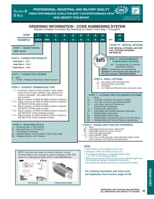
P O S I T R O N I C I N D U S T R I E S<strong>Combo</strong>-DD-SubPROFESSIONAL, INDUSTRIAL AND MILITARY QUALITYTHREE PERFORMANCE LEVELS FOR BEST COST/PERFORMANCE RATIOHIGH DENSITY PCB MOUNTNEW!<strong>Positronic</strong> <strong>Industries</strong>connectpositronic.comORDERING INFORMATION - CODE NUMBERING SYSTEMSpecify Complete Connector By Selecting An Option From Step 1 Through 8STEPEXAMPLE1 2 3 4 5 6 7 8 9CBCD 8W2 S 0 0 0 0 S /AA10-14STEP 1 - BASIC SERIESCBCD SeriesSTEP 2 - CONNECTOR VARIANTSShell Size 1 - 8W2Shell Size 2 - 19W1* 1 Shell Size 4 - 45W2STEP 3 - CONNECTOR GENDERM - MaleS - Female - PosiBand Closed Entry Signal ContactsSTEP 4 - CONTACT TERMINATION TYPE0 – Connector ordered without contacts. Order signal,power, thermocouple, shielded, high voltage or aircontacts separately. See pages 68-80 for contactpart numbers.1 – Signal contacts, 22 AWG-30 AWG [0.03mm 2 -0.05mm 2 ].* 2 11 – Signal contacts, 22 AWG-30 AWG [0.03mm 2 -0.05mm 2 ]with MC/FC 4012D power contact.* 2 12 – Signal contacts, 22 AWG-30 AWG [0.03mm 2 -0.05mm 2 ]with MC/FC 4016D power contact.* 2 13 – Signal contacts, 22 AWG-30 AWG [0.03mm 2 -0.05mm 2 ]with MCC/FCC 4101D shielded contacts.* 2 14 – Signal contacts, 22 AWG-30 AWG [0.03mm 2 -0.05mm 2 ]with MCC/FCC 4102D shielded contacts.* 3 STEP 5 - MOUNTING STYLE0 – Mounting Hole, 0.120 [3.05] Ø02 – Mounting Hole, 0.154 [3.91] ØF – Float Mounts, UniversalS2 – Swaged Spacer, 4-40 Threads, 0.125 [3.18] LengthS5 – Swaged Locknut, 4-40 ThreadsRoHS• per EU Directive 2002/95/ECSTEP 9 - ENVIRONMENTALCOMPLIANCE OPTIONS/AA - Compliant per EU Directive2002/95/EC (RoHS)NOTE: If compliance to environmentallegislation is not required, this step will notbe used. Example: CBCD8W2S0000S•* 3 STEP 10 - SPECIAL OPTIONSFOR SPECIAL OPTIONS, SEE SPE-CIAL OPTIONS APPENDIXON PAGE 89.STEP 8 - SHELL OPTIONS0 – Zinc Plated, with Chromate Seal.* 5 S – Stainless Steel, passivated.X – Tin Plated.Z – Tin Plated and Dimpled (male connectors only).* 3 STEP 7 - LOCKING AND POLARIZING SYSTEMS0 – None.V3 – Lock Tab, connector front panel mounted.V5 – Lock Tab, connector rear panel mounted.VL – Lock Lever, used with Hoods only.T – Fixed Female Jackscrews.T2 – Fixed Female Jackscrews.T6 – Fixed Male and Female Polarized Jackscrews.E – Rotating Male Jackscrews.E2 – Rotating Male Screw Locks.E3 – Rotating Male with Internal Hex for 3/32 Hex DrivesE6 – Rotating Male and Female Polarized Jackscrews.* 3 STEP 6 - HOODS AND PUSH-ON FASTENERS0 – NoneAN – Lightweight Aluminum Hood, nickel finish.AC – Lightweight Aluminum Hood, no finish.H – Hood, Top Opening, Metal* 4 G – Hood, EMI/RFI, MetalZ – Hood, Top or Side Opening, robust extended height, plasticand composite, with rotating male jackscrewsNOTE: Once you have made a connector selection, contactTechnical Sales if you would like to receive a drawing in DXF, PDFformat or a 3-dimensional IGES, STEP, or SOLIDWORKS file.NOTES* 1 45W2 variant currently available in female only.* 2 Available on 19W1 and 45W2 connectors only.* 3 For additional information on accessories listed in steps5, 6, 7 and 10, see Accessory Catalog.* 4 When using G hood with CBCD variants, use the extended height hood.See Accessories Catalog for extended G hood options.* 5 For stainless steel dimpled male versions, contact Technical Sales.SK Drawing3-dimensional modelFor crimping information and crimp tools,see Application Tools section, pages 81-89.CBCD SERIESDIMENSIONS ARE IN INCHES [MILLIMETERS].ALL DIMENSIONS ARE SUBJECT TO CHANGE.42