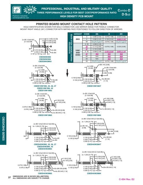
37<strong>Positronic</strong> <strong>Industries</strong>connectpositronic.comNEW!PROFESSIONAL, INDUSTRIAL AND MILITARY QUALITYTHREE PERFORMANCE LEVELS FOR BEST COST/PERFORMANCE RATIOHIGH DENSITY PCB MOUNT<strong>Combo</strong>-DD-SubPRINTED BOARD MOUNT CONTACT HOLE PATTERNHOLE IDENTIFICATION SHOWN FOR MALE CONNECTOR; USE MIRROR IMAGE FOR FEMALE CONNECTOR.MOUNT RIGHT ANGLE (90°) CONNECTOR WITH MATING FACE POSITIONED TO FOLLOW DIRECTION OF ARROWS.2x Ø0.123±0.003[3.12±0.08]A1B0.010 [0.25]B0.055 [1.40]0.187 [4.75] Typ.BB1 25A2CBDD8W2M3CBDD8W2M4CBDD8W2M932x Ø0.123±0.003[3.12±0.08]2x 0.656[16.66]713715A10.160 [4.06]0.205 [5.21]0.090 [2.29] Typ.1962x 0.492 [12.50]0.080 [2.03]0.035 [0.89]441016618122x ØA6x ØC18x ØCØACBDD19W1M3, 35, 36, 37CBDD19W1M4, 45CBDD19W1M932x Ø0.123±0.003[3.12±0.08]2x 0.656[16.66]13A1460.100 [2.54]0.100 [2.54]SUGGESTEDPRINTED BOARD HOLE SIZESVARIANT CODE ØA B ØC8W219W1AND45W213 150.100 [2.54]0.160 [4.06]0.100 [2.54]0.205 [5.21]0.090 [2.29] Typ.3 0.080 [2.03] 0.078 [1.98] 0.035 [0.89]4 0.080 [2.03] 0.100 [2.54] 0.045 [1.14]93See chart for size 16contact on page 87. 0.078 [1.98]See chart for size 22contact on page 87.3, 35 0.098 [2.49]36 0.114 [2.90]37 0.145 [3.68]2x 0.656[16.66]7193A14161061812CBDD19W1M472x Ø0.123±0.003[3.12±0.08]2x 0.656[16.66]13A146Ø0.145 [3.68]0.078 [1.98] 0.035 [0.89]4, 45 0.098 [2.49] 0.100 [2.54] 0.045 [1.14]47 N/A N/A N/A65 N/A N/A N/A84 N/A N/A N/ASee chart for size 8See chart for size 2293 contact on page 87. 0.078 [1.98] contact on page 87.2x Ø0.123±0.003[3.12±0.08]0.396 [10.06]18x Ø0.045[1.14]0.156 [3.96]0.056 [1.42]0.044 [1.12]CBDD/CBHD SERIESBB2x 1.250 [31.75]162x Ø0.123±0.003 [3.12±0.08]130172236A1A20.100 [2.54]0.308 [7.82]0.095 [2.41] Typ.2x 1.250 [31.75]77A1913 15 16 180.078 [1.98]0.160 [4.06]0.078 [1.98]0.205 [5.21]18x Ø0.035 [0.89]0.090 [2.29] Typ.3x Ø0.045 [1.14]CBDD19W1M65A20.358 [9.09]0.150 [3.81]CBDD45W2M3, 35, 36, 37CBDD45W2M4, 45CBDD45W2M932x Ø0.123±0.003 [3.12±0.08]10823812430.358 [9.09]0.150 [3.81]152943x ØC2x ØA150.100 [2.54]0.100 [2.54]0.100 [2.54]13 15 16 180.100 [2.54]0.160 [4.06]0.100 [2.54]0.205 [5.21]0.090 [2.29] Typ.CBDD19W1M840.100 [2.54]2x Ø0.123±0.003 [3.12±0.08]2x 1.250 [31.75]2x Ø0.145[3.68]16130172236A10.100 [2.54]0.308 [7.82]0.095 [2.41] Typ.CBDD45W2M472x 1.250 [31.75]77A1A2A20.358 [9.09]0.150 [3.81]2x Ø0.123±0.003 [3.12±0.08]91082337812430.358 [9.09]0.150 [3.81]21x Ø0.045 [1.14]152943x Ø0.045[1.14]150.396 [10.06]0.156 [3.96]0.056 [1.42]0.044 [1.12]1622232916222329370.078 [1.98]0.078 [1.98]30360.100 [2.54]0.308 [7.82]0.095 [2.41] Typ.37CBDD45W2M65DIMENSIONS ARE IN INCHES [MILLIMETERS].ALL DIMENSIONS ARE SUBJECT TO CHANGE.430.100 [2.54]0.100 [2.54]43x Ø0.035 [0.89]6x Ø0.045 [1.14]3036370.100 [2.54]0.308 [7.82]0.095 [2.41] Typ.CBDD45W2M844350x Ø0.045 [1.14]C-004 Rev. E2
P O S I T R O N I C I N D U S T R I E S<strong>Combo</strong>-DD-SubPROFESSIONAL, INDUSTRIAL AND MILITARY QUALITYTHREE PERFORMANCE LEVELS FOR BEST COST/PERFORMANCE RATIOHIGH DENSITY PCB MOUNTNEW!<strong>Positronic</strong> <strong>Industries</strong>connectpositronic.comORDERING INFORMATION - CODE NUMBERING SYSTEMSpecify Complete Connector By Selecting An Option From Step 1 Through 8FOR CONNECTORSNOT INCLUDING SIZE 8 CONTACTSSTEP 3 - CONNECTOR GENDER* 1 F - Female - Professional Level -Open Entry Signal ContactsM - Male* 1 S - Female - Industrial / Military Level -PosiBand Closed Entry Signal Contacts1 2 3 4 5 6 7 8 9CBDD 8W2 M 93 S 0 0 0 /AA* 2 STEP 5 - MOUNTING STYLE0 – Mounting Hole, 0.120 [3.05] Ø02 – Mounting Hole, 0.154 [3.91] ØB3 – Bracket, Mounting, Right Angle (90°) Metal with Cross BarB8 – Bracket, Mounting, Right Angle (90°) Plastic with Cross BarF – Float Mounts, UniversalP – Threaded Post, Brass, 0.250 [6.35] LengthP2 – Threaded Post, Nylon, 0.250 [6.35] LengthR2 – Bracket, Mounting, Right Angle (90°) Metal, Swaged to Connectorwith 4-40 Thread Fixed Female Jackscrews with Cross BarR6 – Bracket, Mounting, Right Angle (90°) Metal, Swaged to Connectorwith 0.120 [3.05] Ø Mounting Hole with Cross BarR7 – Bracket, Mounting, Right Angle (90°) Metal, Swaged to Connectorwith 4-40 Threads with Cross BarR8 – Bracket, Mounting, Right Angle (90°) Metal, Swaged to Connectorwith 4-40 Locknut with Cross BarSSTEPEXAMPLESTEP 1 - BASIC SERIESCBDD Series -CBHD Series - High ConductivityPower ContactsSTEP 2 - CONNECTOR VARIANTSShell Size 1 - 8W2See next page for ordering information forother shell size options.STEP 4 - CONTACT TERMINATION TYPE21 – Fixed Solder Cup, 22 AWG-30 AWG [0.3mm2-0.05mm2].3 – Solder, Straight Printed Board Mount, 0.170 [4.32] Taillength.4 – Solder, Right Angle (90°) Printed Board Mount, 0.314[7.98] Signal Contact Extension.93 – Signal Omega type compliant and Power Bi-Spring typecompliant, termination length 0.225 [5.72].– Swaged Spacer, 4-40 Threads, 0.250 [6.35] Length, Spacerlength changes to 0.265 [6.73] when used in conjunction withCode 93 contactsS2 – Swaged Spacer, 4-40 Threads, 0.125 [3.18] LengthS5 – Swaged Locknut, 4-40 ThreadsS6 – Swaged Spacer with Push-on Fastener, 4-40 Threads, 0.250[6.35] LengthRoHS• per EU Directive 2002/95/EC•10-14* 2 STEP 10 - SPECIAL OPTIONSFOR SPECIAL OPTIONS, SEESPECIAL OPTIONS APPENDIXON PAGE 89.CONTACT TECHNICAL SALESFOR ORDERING DETAILS OFTHE FOLLOWING:Other Special Requirements.Straight and Right Angle ThermocouplePCB mount contactsSTEP 9 - ENVIRONMENTALCOMPLIANCE OPTIONS/AA - Compliant per EU Directive2002/95/EC (RoHS)NOTE: If compliance to environmentallegislation is not required, this step will notbe used. Example: CBDD8W2M93S000STEP 8 - SHELL OPTIONS0 – Zinc Plated, with Chromate Seal.* 4 S – Stainless Steel, passivated.X – Tin Plated.Z – Tin Plated and Dimpled (male connectors only).* 2 STEP 7 - LOCKING AND POLARIZING SYSTEMS0 – None.V3 – Lock Tab, connector front panel mounted.V5 – Lock Tab, connector rear panel mounted.VL – Lock Lever, used with Hoods only.T – Fixed Female Jackscrews.T2 – Fixed Female Jackscrews.T6 – Fixed Male and Female Polarized Jackscrews.E – Rotating Male Jackscrews.E2 – Rotating Male Screw Locks.E3 – Rotating Male with Internal Hex for 3/32 Hex DrivesE6 – Rotating Male and Female Polarized Jackscrews.* 2 STEP 6 - HOODS AND PUSH-ON FASTENERS0 – NoneAN – Lightweight Aluminum Hood, nickel finishAC – Lightweight Aluminum Hood, no finishH – Hood, Top Opening, Metal* 3 G – Hood, EMI/RFI, MetalN – Push-on Fastener, for Right Angle (90°) Mounting BracketsZ – Hood, Top or Side Opening, robust extended height, plasticand composite, with rotating male jackscrewsCBDD/CBHD SERIESNOTES* 1 Power contacts are always supplied with “Closed Entry” female contacts.* 2 For additional information on accessories listed in steps5, 6, 7 and 10, see Accessory Catalog.* 3 When using G hood with CBDD variants, use the extended height hood.See Accessories Catalog for extended G hood options.* 4 For stainless steel dimpled male versions, contact Technical Sales.C-004 Rev. E2DIMENSIONS ARE IN INCHES [MILLIMETERS].ALL DIMENSIONS ARE SUBJECT TO CHANGE.38
- Page 1 and 2: Catalog C-004 Rev. E2
- Page 3: P O S I T R O N I C I N D U S T R I
- Page 6 and 7: APPLICATION TOOLS SPECIAL OPTIONS D
- Page 8: GENERAL INFORMATIONRATED CURRENT (A
- Page 11 and 12: Combo-DD-SubPROFESSIONAL, INDUSTRIA
- Page 13 and 14: Combo-DD-SubPROFESSIONAL, INDUSTRIA
- Page 15 and 16: Combo-DD-SubPROFESSIONAL, INDUSTRIA
- Page 17 and 18: Combo-DD-Sub0.125 [3.18] ØTyp.0.22
- Page 19 and 20: Combo-DD-SubPROFESSIONAL, INDUSTRIA
- Page 21 and 22: Combo-DD-SubPROFESSIONAL, INDUSTRIA
- Page 23 and 24: Combo-DD-SubPROFESSIONAL, INDUSTRIA
- Page 25 and 26: Combo-DD-SubPROFESSIONAL, INDUSTRIA
- Page 27 and 28: Combo-DD-SubPROFESSIONAL, INDUSTRIA
- Page 29 and 30: P O S I T R O N I C I N D U S T R I
- Page 31 and 32: 1Combo-DD-SubPROFESSIONAL, INDUSTRI
- Page 33 and 34: P O S I T R O N I C I N D U S T R I
- Page 35 and 36: Combo-DD-SubPROFESSIONAL, INDUSTRIA
- Page 37 and 38: Combo-DD-SubPROFESSIONAL, INDUSTRIA
- Page 39 and 40: Combo-DD-SubPROFESSIONAL, INDUSTRIA
- Page 41 and 42: Combo-DD-SubPROFESSIONAL, INDUSTRIA
- Page 43: Combo-DD-SubPROFESSIONAL, INDUSTRIA
- Page 47 and 48: P O S I T R O N I C I N D U S T R I
- Page 49 and 50: Positronic Industriesconnectpositro
- Page 51 and 52: P O S I T R O N I C I N D U S T R I
- Page 53 and 54: CBDPB/CBDPC SERIESPositronic Indust
- Page 55 and 56: CBDPB/CBDPC SERIESPositronic Indust
- Page 57 and 58: P O S I T R O N I C I N D U S T R I
- Page 59 and 60: Combo-DD-SubMicroTCA POWERINPUT CON
- Page 61 and 62: Combo-DD-SubMicroTCA POWERINPUT CON
- Page 63 and 64: Combo-DD-SubMicroTCA POWERINPUT CON
- Page 65 and 66: Combo-DD-SubMicroTCA POWERINPUT CON
- Page 67 and 68: Combo-DD-SubMicroTCA POWERINPUT CON
- Page 69 and 70: P O S I T R O N I C I N D U S T R I
- Page 71 and 72: Combo-DD-SubCOMBO-DCONNECTOR SAVERS
- Page 73 and 74: P O S I T R O N I C I N D U S T R I
- Page 75 and 76: Combo-DD-SubNEW!UNIQUE FEATURESPosi
- Page 77 and 78: Combo-DD-SubNEW!UNIQUE FEATURESPosi
- Page 79 and 80: Combo-DD-SubNEW!UNIQUE FEATURESPosi
- Page 81 and 82: Combo-DD-SubNEW!REMOVABLE CONTACTSP
- Page 83 and 84: Combo-DD-SubNEW!REMOVABLE CONTACTSP
- Page 85 and 86: Combo-DD-SubNEW!REMOVABLE CONTACTSP
- Page 87 and 88: Combo-DD-SubNEW!REMOVABLE CONTACTSP
- Page 89 and 90: Combo-DD-SubNEW!REMOVABLE CONTACTSP
- Page 91 and 92: Combo-DD-SubNEW!REMOVABLE CONTACTSP
- Page 93 and 94: Combo-DD-SubNEW!REMOVABLE CONTACTSP
- Page 95 and 96:
Combo-DD-SubSTEP 2: CRIMP WIRE TO C
- Page 97 and 98:
Combo-DD-SubAPPLICATION TOOLSCRIMPI
- Page 99 and 100:
Combo-DD-Sub16 MC120N-133.0 9501-0-
- Page 101 and 102:
Combo-DD-Sub1/2 inch shaftfor arbor
- Page 103 and 104:
Combo-DD-SubDESC CROSS REFERENCE* 1
- Page 105 and 106:
POSITRONIC INDUSTRIESPositronic Pro