Design and Analysis of Kinematic Couplings for Modular Machine ...
Design and Analysis of Kinematic Couplings for Modular Machine ...
Design and Analysis of Kinematic Couplings for Modular Machine ...

Create successful ePaper yourself
Turn your PDF publications into a flip-book with our unique Google optimized e-Paper software.
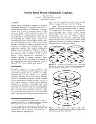
While at the small scale, repeatability <strong>of</strong> kinematic couplings has been proven to be more than sufficient<strong>for</strong> most industrial applications, interchangeability has not yet been studied in detail. The fundamentalcontribution <strong>of</strong> this analysis is a statistical model <strong>of</strong> mechanical interchangeability <strong>of</strong> the canoe ball <strong>and</strong>three-pin coupling interfaces. Parametric relationships result in terms <strong>of</strong> the manufacturing tolerances onthe couplings <strong>and</strong> interface plates, the error <strong>of</strong> the coupling mounting <strong>and</strong> measurement processes, <strong>and</strong> thedetail <strong>of</strong> pre-calibration <strong>of</strong> the contact point locations. Simplification <strong>of</strong> this model to traditional ballgroovecouplings, or extension to inexact constraint quasi-kinematic couplings <strong>for</strong> which a minimumenergyconfiguration must be found, is straight<strong>for</strong>ward future work.3.2 Global Error Model <strong>of</strong> a <strong>Kinematic</strong> Coupling InterfaceRecalling that the six-points <strong>of</strong> contact from a kinematic coupling exactly constrain a solid body, kinematiccouplings can be exploited as minimum geometric error interfaces <strong>for</strong> two main reasons. First, the<strong>for</strong>ced point-line contact <strong>of</strong> the ball triangle on the groove lines reduces the positional error <strong>of</strong> the couplingcentroid to one-third the error <strong>of</strong> the coupling positions. Second, the deterministic point-line contactenables calculation <strong>of</strong> an error trans<strong>for</strong>mation between the nominal interface mating position <strong>and</strong> the truemating position, when the position <strong>and</strong> orientation <strong>of</strong>fsets <strong>of</strong> the balls <strong>and</strong> grooves are known. Furthermore,at a very fine scale, the mechanical error motion <strong>of</strong> the interface from Hertzian contact between theballs <strong>and</strong> grooves can be determined [2]. However, at even extreme interface preloads <strong>and</strong> disturbancesthis error motion is very small compared to the magnitude <strong>of</strong> the kinematic trans<strong>for</strong>mation due to error inthe coupling placements from typical CNC machining processes. Because <strong>of</strong> this determinism, the kinematicerror <strong>of</strong> the coupling interface can be expressed in closed <strong>for</strong>m.To start the error model, consider a general machine design application in which two modules matethrough an interface <strong>of</strong> canoe ball kinematic couplings, shown in Figure 3.1 <strong>for</strong> the base interface <strong>of</strong> anindustrial robot. The grooves sit on a fixed floor-mounted lower module, <strong>and</strong> the mating balls are attachedto the upper module. Reference coordinate frames are placed centroidally on the groove set (F groove ) <strong>and</strong>the ball set (F ball ), <strong>and</strong> the couplings are secured using a sufficient (bolted or magnetic) preload. For themachining task, the tool center point (TCP) <strong>and</strong> co-located coordinate frame (F TCP ) are <strong>of</strong>fset from the ball40