40 Chapter II 6-Cylinder EnginesCRANKSHAFT SPROCKETREAR OIL SEALFRONT OIL SEALSCREWWASHERSCREWCLUTCH PILOTBEARINGLOCKWASHERSCREWJR FRONT AND INTERMEDIATt~gL BEARING CAPBEARING CAPSIDE OIL SEALSFLYWHEEL ASSEMBLY6502Fig. 23 Crankshaft and Related PartsTRANSMISSION. Remove the transmission. Removethe flywheel housing dust cover. Mark the clutch assembly so it can be replaced in the same position. Removethe clutch release rod, spring, and bearing. Remove theclutch pressure plate and disc (Tool-7563). Remove theflywheel retaining bolts and pry the flywheel off thecrankshaft. Remove the flywheel through the housinglower access opening.CAUTION: Do not get grease or oil on the clutch<strong>com</strong>ponents.(2) INSTALLATION STANDARD OR OVERDRIVE TRANSMISSION. Position the flywheel onthe crankshaft flange and align the bolt holes, theninstall the mounting bolts. Tighten the bolts in sequenceacross from each other to 75-85 foot-pounds torque.Using a pilot shaft (Tool-6392-N)to locate the clutchdisc, install the pressure plate and disc. Install theclutch release rod, bearing, spring, and hub. Install theflywheel housing dust cover. Install the transmission.(3) REMOVAL FORDOMATIC. Remove the tworubber plugs from the floor pan, then remove the converter housing to engine block upper bolts. Raise thefront of the car and position safety stands. Remove thetransmission control linkage shield, the torque converterlower access plate, the torque converter air inlet shield,and the torque converter front access plate. Turn thetorque converter until the drain plug is at the loweredge. Drain the transmission and torque converter.Remove the drive shaft. Disconnect the speedometercable and transmission control rod at the transmission.Remove the battery cable from the starter,then removethe starter. Remove the transmission oil level indicatortube.Install the drain plug in the torque converter. Position a jack under the transmission. Remove the transmission support bolts. Remove the frame cross memberat the rear of the transmission. Remove the two lowerbolts securing the torque converter housing to theengine block. Move the transmission back far enough toclear the flex drive plate. Secure the torque converterto the housing.CAUTION: // the torque converter is not secured, itwill slideoffthe splines.Remove the flex drive plate from the crankshaft.(4) INSTALLATION FORDOMATIC. Position theflex drive plate on the crankshaft and align the boltholes, then install the mounting bolts. Tighten the boltsto 75-85 foot-pounds torque. Align the converter pilotand the housing dowel holes, then install the torqueconverter housingto engine block lower bolts. Installthe flex plate to converter bolts. Install the frame crossmember. Remove the jack. Install the transmission rearsupport bolts.Connect the transmission throttle control linkage, themanual control linkage, and the speedometer cable.Install the torque converter air inlet shield, controllinkage shield, torque converter housing front accesscover, the torque converter lower access cover,transmission oil level indicator tube.Install the starter, then connect the batteryand thecable tothe starter. Install the drive shaft. Remove the safetystands and lower the car. Install the converterhousingto engine block bolts. Install the rubber plugs and position the floor mat.Fill the transmission with fluid. Start the engine tofill the torque converter, then add fluid until the properlevel is reached on the oil level indicator. Check for
Section 7 Flywheel, Crankshaft, and Main Bearings 41leaks. Check and adjust the manual control, the neutralswitch, and the throttle linkage.b. Crankshaft.The crankshaft is precision-molded, alloy iron withintegral counterweights and is statically and dynamically balanced. Oil distribution holes are drilled throughthe shaft to pressure lubricate the main and connectingrod bearings.NOTE: Handle the crankshaft with care to avoidpossible fractures or damage to the finished surfaces.(1) REMOVAL. Remove the engine and install iton a work stand. Remove the flywheel housing, clutchassembly, flywheel or flex drive plate, and the enginerear plate. Mark the clutch pressure plate assembly soit can be installed in the same position on the flywheel.Remove the crankshaft damper, cylinder front cover,sprockets and timing chain. Remove the oil pan and theoil pump screen housing assembly.Make sure all bearing caps (main and connectingrod) are marked so they can be installed in theiroriginal locations. Remove the connecting rod bearingcaps, using care not to intermix the caps, then push thepistons to the topof the cylinders.Remove the mainbearing caps, and mark them forinstallation on the same journals. <strong>Car</strong>efully lift thecrankshaft out of the block so the thrust bearing surfaces are not damaged. Remove the rear journal oil sealfrom the block and rear bearing cap, and remove thecap to block side seals.(2)INSTALLATION. Be sure the bearings and thecrankshaft journals are clean. Install a new rear journaloil seal in the block and rear main bearingfully lower the crankshaft into place.cap. <strong>Car</strong>eCAUTION: Be careful not to damage the bearingsurfaces.Check the clearance of each main bearing usingPlastigage (Chapter I). After the clearance has beenchecked and found to be satisfactory, apply a light coatof engine oil to the journals and bearings, then installall the bearing caps except the thrust bearing cap.Install new side seals when the rear main bearing capis installed. Install the thrust bearing cap and draw thecap bolts up lightly, then align the thrust bearingbolts to specifications.(Chapter I). Tighten the capCheck the crankshaft end play (Chapter I).Install the connecting rod caps in their original positions. Check the bearing clearance, using Plastigage(Chapter I). After the clearance has been checked andfound to be satisfactory, apply a light coat of engineoil to the journals and bearings, then install the rodcaps. Tighten the nuts to 45-50 foot-pounds torque.Install the pal nuts and tighten them to 3-4 foot-poundstorque. Check the end play of each rodconnecting(Chapter I).Install the engine rear plate. Install the flywheel orflex drive plate. Align the clutch disc (Tool-6392-N),<strong>com</strong>press the clutch pressure plate and springs,installthe pressure plate assembly. Install the flywheel housing. Install the sprockets and timingchain. Install thecylinder front cover, oil pump screen assembly and oilpan, the crankshaft damper, and belt.On cars equipped with power steering, install thepower steering pump pulley and belt.Install the engine in the car. Fill the crankcase, thenstart the engine and check for oil pressure and oil leaks.c. Main Bearings.The main bearings are the steel-backed, copper-lead,or lead-babbitt insert-type.Crankshaft end play is controlled by the number 3main bearing flanges.If the crankshaft has been removed, new bearings canbe readily fitted. However, the bearings can be fittedwith the engine in the chassis as follows:Remove the oil pan, then remove the oil pump.NOTE: Replace one bearingat a time, leaving theother bearings securely fastened.Remove the main bearing cap to which new bearings are to be fitted. Insert the upper bearing removaltool (Tool 6-331) in the oil hole in the crankshaft.Rotate the crankshaft in the opposite direction to enginerotation to force the bearing out of the block.NOTE: When replacingstandard bearings with newbearings, it is good practice to first tryproper clearance with two blue bearing halves.to obtain theTo install the upper main bearing, place the plainend of the bearing over the shaft on the locking tangside of the block. Using the same tool,rotate the crankshaft in the direction of engine rotation until the bearingseats itself. Remove the tool. Replace the bearing cap.Clean the crankshaft journal and bearings. Check thebearing clearance using Plastigage (Chapter I). Afterthe clearance has been checked and found to be satisfactory, apply a light coat of engine oil to the journalsand bearings, then install the bearing cap. Tighten thebolts to 95-105 foot-pounds torque.If the rear mainbearing is replaced, replace thejournal oil seals and the side seals.Install the oil pump and oil pan. Fill the crankcase,then start the engine and check for oil pressure and oilleaks.
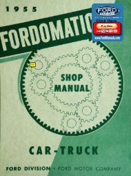
- Page 1 and 2: 19 5 6FORDDIVISIONM O T O COMPANY
- Page 3 and 4: -19 5 6Copyright 1955FORD MOTOR COM
- Page 5 and 6: .- ..49.... 78.847414551011.Forewor
- Page 7 and 8: cessories."SectionPart ONEPOWER PLA
- Page 9 and 10: Section 1 Trouble Shooting(d) If th
- Page 11 and 12: Section 2 Engine Tune-Uptributor va
- Page 13 and 14: Section 3 Engine Removal and Instal
- Page 15 and 16: up"Section 3 Engine Removal and Ins
- Page 17 and 18: Section 4 Intake and Exhaust Manifo
- Page 19 and 20: S-8680Section 5 Rocker Mechanism, C
- Page 21 and 22: Section 5 Rocker Mechanism, Cylinde
- Page 23 and 24: Section 6 Timing Chain, Sprockets,
- Page 25 and 26: up9'Section 7 Flywheel, Crankshaft,
- Page 27 and 28: Section 7 Flywheel, Crankshaft, and
- Page 29 and 30: Section 8 Cylinder Block, Pistons,
- Page 31 and 32: Section 8 Cylinder Block, Pistons,
- Page 33 and 34: SectionPart ONEPOWER PLANTChapter6-
- Page 35 and 36: Section 2 Manifolds 33c. Installati
- Page 37 and 38: ~~Section 3 Cylinder Head and Valve
- Page 39 and 40: Section 5 Cylinder Front Cover and
- Page 41: STANDARDSection 6 Sprockets andTimi
- Page 45 and 46: Section 8 Connecting Rods and Beari
- Page 47 and 48: Section 9 Oil Pan, Oil Filter, and
- Page 49: LITHO IN U.S.A.7098-56