Eberspacher D3LC Compact 1998 Heater Installation ...
Eberspacher D3LC Compact 1998 Heater Installation ...
Eberspacher D3LC Compact 1998 Heater Installation ...
- No tags were found...

Create successful ePaper yourself
Turn your PDF publications into a flip-book with our unique Google optimized e-Paper software.
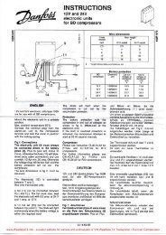
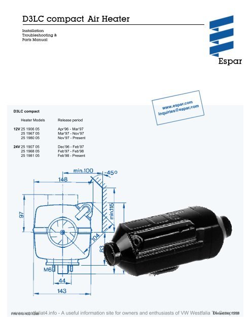
<strong>D3LC</strong> compact Air <strong>Heater</strong><strong>Installation</strong>Troubleshooting &Parts ManualEspar<strong>D3LC</strong> compact<strong>Heater</strong> ModelsRelease period12V 25 1906 05Apr’96 - Mar’9725 1967 05 Mar’97 - Nov’9725 1980 05 Nov’97 - Present24V 25 1907 05Dec’96 - Feb’9725 1968 05 Feb’97 - Feb’9825 1981 05 Feb’98 - Presentwww.westfaliat4.info - A useful information site for owners and enthusiasts of VW Westfalia T4 December Campers <strong>1998</strong>P/N: 610-102-1298
Table of contentsPage#Introduction General Specifications 3<strong>Heater</strong> Warnings 4Introduction 5Principal Dimensions 6Mounting Pattern 6<strong>Heater</strong> Components 7<strong>Installation</strong> Procedures <strong>Heater</strong> Location 8<strong>Heater</strong> Mounting 8<strong>Heater</strong> Air Ducting 8Fuel System 10Electrical Connections 12Exhaust & Combustion Air Intake Connections 13Operating Switches 13<strong>Heater</strong> Operation Switch On 14Start Up 14Temperature Setting 14Temperature Control 14Switch Off 14Controls and Safety Equipment 14Operation Flow Chart 15Maintenance, Wiring Diagrams - model 25 1980/1981 16Troubleshooting Wiring Diagrams - model 25 1967/1968 17& Repairs Wiring Diagrams - model 25 1906/1907 18Recommended Periodic Maintenance 19Basic Troubleshooting 19Self Diagnostics 20Fuel Quantity Test 24Components Specification Chart 24Repair Steps 25<strong>Heater</strong> Parts <strong>D3LC</strong> compact - Service Parts Diagram 28<strong>D3LC</strong> compact - Parts List 32Special NotesNote: Highlight areas requiring special attention or clarification.Caution: Indicates that personal injury or damage to equipment may occur unless specific guidelines are followed.Warning: Indicates that serious or fatal injury may result if specific guidelines are not followed.This publication was correct at the time of print. However, Espar Inc. has a policy of continuous improvement and reserves theright to amend any specifications without prior notice.www.westfaliat4.info - A useful information site for owners and enthusiasts of VW Westfalia T4 Campers
3<strong>Heater</strong> WarningsWarning To Installer:Correct installation of this heater is necessary toensure safe and proper operation.Read and understand this manual before attempting toinstall the heater.Warning - Explosion Hazard1. <strong>Heater</strong> must be turned off while re-fueling.2. Do not install heater in enclosed areas where combustiblefumes may be present.3. Do not install heaters in engine compartments of gasolinepowered boats.Warning - Fire Hazard1. Install heater so it will maintain a minimum distance of2” from any flammable or heat sensitive material.2. Install the exhaust system so it will maintain a minimumdistance of 2” from any flammable or heatsensitive material.3. Ensure that the fuel system is intact and there are noleaks.Failure to follow these instructions could cause fireresulting in serious or fatal injury.Warning - Asphyxiation Hazard1. Route the heater exhaust so that exhaust fumes cannotenter any passenger compartments.2. Ensure an air tight seal will be maintained between theheater and mounting surface and at any exhaust connectionpoints.3. Ensure that heating air supply is taken from an areawhere poisonous gases will not be present.4. If running exhaust components through an enclosedcompartment, ensure that it is vented to the outside.Failure to follow these instructions could cause oxygendepletion resulting in serious or fatal injury.Direct questions to Espar <strong>Heater</strong> SystemsUSA 1-800-387-4800CDA 1-800-668-5676www.westfaliat4.info - A useful information site for owners and enthusiasts of VW Westfalia T4 Campers
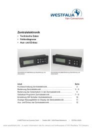
7<strong>Heater</strong> ComponentsParts List1 Hot Air Blower Wheel 11 Operating Unit (Rheostat) F = Fresh Air2 Blower Motor 12 Outer Casing C = Combustion Air3 Combustion Air Blower Wheel 13 Exhaust Line D = Fuel4 Glow Plug 14 Flange Seal H = Hot Air5 Control Unit 15 Fuel Line E = Exhaust6 Safety Thermal Sensor 16 Main Fuse, 25 A7 Combustion Chamber 17 Combustion Air Intake Line8 Flame Monitor 18 Fuel Metering Pump9 Heat Exchanger 19 Fuel Strainer10 Operating Unit (Thermostat) 20 7 Day Timer (optional)www.westfaliat4.info - A useful information site for owners and enthusiasts of VW Westfalia T4 Campers
8<strong>Installation</strong> Procedures<strong>Heater</strong> LocationDepending on the type of vehicle, the best location for mountingthe heater will vary. Typically, heaters aremounted inside tool or luggage compartments. However, theheater may be mounted anywhere inside thevehicle provided you adhere to the following conditions:• Combustion air intake, exhaust and fuel inlet must belocated outside of vehicle.• <strong>Heater</strong> must be mounted on flat horizontal surface providingan air tight seal between heater and vehicle.• Do not mount the heater outside the vehicle, unless careis taken to protect the heater from the weather.When selecting the location, consider the following:<strong>Heater</strong> MountingAmounting plate and hardware are provided with the heater kit.• Choose heater location.• Using template provided, drill and cut center hole. Cutone (1) four and one half inch (41/2”) diameter hole orone rectangular hole four (4”) by five (5”) inches.• Mount heater on mounting plate with nuts and springwashers provided.• For ease of installation make the exhaust, combustionair intake and fuel connections at base of heater beforemounting the heater into the vehicle.• Position heater in vehicle and secure with “Tek” screwsprovided.• Combustion air and exhaust connections.• Ducting.• Fuel line connections.• Electrical connections.Note:Tighten screws sufficiently to ensure positiveseal between mounting plate andmounting surface. Do not over tighten.Mounting Plate <strong>Installation</strong>HEX HEAD TEK SCREWFLATWASHERSILICONE GASKETS.S. PLATEPLATE SEALNUTSPRING WASHER<strong>Heater</strong> Air Ducting<strong>Installation</strong>A 90mm flexible duct 40 inches long, hot air outlet andclamps are provided with the heater kit. In routing andinstalling the ducting the following criteria must beobserved:• Run ducting with smooth bends. Avoid crushing duct.• Position hot air outlet so that it cannot be obstructed.• Use protective air intake grille on air inlet side of heaterto prevent objects from being sucked in.• Ensure provisions are made for proper air return ventilation.• Use return air ducting for best heating efficiencywww.westfaliat4.info - A useful information site for owners and enthusiasts of VW Westfalia T4 Campers
9Return DuctingDucting Components1. Protective Grill 3. Hose Clamp 2-2 3/4” 5. Air Outlet - Rotatable 7. 90° Bend Ducting 2 3/8”2. Air Outlet Hood 4. Flex Duct 3” or 90mm 6. Connection PieceWarning:Do not use existing vehicle ducting oroutlets. Ducts and outlets must becapable of withstanding a minimumof 300°F operating temperatures.To avoid exhaust leakage, theheater must always be operatedwith an end cap installed.Caution:Do not over tighten duct clamps.Do not position outlet so that it willblow hot air directly at operator or atroom thermostat.www.westfaliat4.info - A useful information site for owners and enthusiasts of VW Westfalia T4 Campers
10Fuel SystemThe fuel metering pump is the heart of the system and mustbe installed properly to ensure a successful heater operation.Fuel System Overview1. Fuel Pick-Up Pipe2. 5.0 Rubber Connector3. 11mm Clamp4. 2.0mm Black Plastic Fuel Line5. Fuel Metering Pump6. 9mm Clamp7. 3.5mm Rubber Connector8. 1.5mm White Plastic Fuel Line9. 5mm Rubber Fuel LineNote:Butt joints and clamps on all connections.OptionalFuel Pick-Up Pipe <strong>Installation</strong> (Standard Pick-Up)• Choose a protected mounting location close to the fuelpump and heater. A spare fuel sender gauge plate providesan ideal mounting location.• Drill the mounting holes as shown• Cut the fuel pick-up pipe to length.• Mount the fuel pick-up pipe as shown.• Lower the fuel pick-up pipe (with reinforcing washer) intothe tank using the slot created by the two 1/4” holes.• Lift the assembly into position through the 1” hole.• Assemble the rubber washer, metal cup washer and nut.Note:Drill the two 1/4” holes first.(Custom Pick-Up Pipe with NPT fitting)• Remove an existing plug from the top of the fuel tank.• Cut the fuel pick-up pipe to length.• Secure the fuel pick-up pipe into position using thecombined NPT compression fitting as shown.NPT fitting and pipeNote:NPT fittings are available in various sizes(Refer to parts section).www.westfaliat4.info - A useful information site for owners and enthusiasts of VW Westfalia T4 Campers
11Fuel Metering Pump• Choose a protected mounting location close to thefuel pick-up pipe and heater.• Using the bracket and rubber mount provided, installfuel pump as shownNote:Proper mounting angle of the fuel pump isnecessary to allow any air or vapor in thefuel lines to pass through the pump ratherthan cause a blockage.Fuel Line• Route fuel lines from the fuel pick-up pipe to the fuelmetering pump then to the heater.• Use fuel lines provided.• Other sizes or types of fuel lines may inhibit properfuel flow.• Make proper butt joints using clamps and connectorpieces as shown on page 8• Use a sharp utility knife to cut plastic fuel lines toavoid burrs.www.westfaliat4.info - A useful information site for owners and enthusiasts of VW Westfalia T4 Campers
12Electrical ConnectionsCaution:Install power fuse only after all electrical connections are complete.Main Harness.......................................................................11 core harness (red/white, green/red, blue/white, red, white,grey/red, grey, brown, brown, brown/white and yellow).Connect to heater control unit (mounted in heater) using the 14 pinconnector then connect glow plug connector.Place protective hood over glow plug and control unit & secure.Connect to other harnesses as described for each harness.Power Harness.....................................................................2 core harness (red and brown).Connect red wire to fuse holder near battery.Connect red fuse link wire to other side of fuse holder.Connect other end of fuse link wire directly to battery positive postusing ring terminal provided.Connect brown wire directly to battery negative post using ring terminalprovided.Run power harness to main harness - connect 2 pin connectorsSwitch Harness....................................................................6 core harness (red, brown/white, yellow, grey, brown and grey/red)Connect to rheostat switch or thermostat (refer to switch connectionsection).Connect switch harness to main harness using 8 pin connector.Fuel Metering Pump Harness.............................................2 core harness (green/red and brown).Connect to fuel metering pump using single terminals and rubberprotective boots (no polarity required).Connect fuel metering pump harness to main harness usingtwo single connectors.Electrical ConnectionsFuel Metering Pump HarnessMain HarnessResistor for models(12V) 25 1967 05(24V) 25 1968 05Fuse and holderSwitch HarnessThermostatPower HarnessNote: All exposed electrical connections shouldbe coated with protective grease. (petroleumgel, Vaseline, etc.).www.westfaliat4.info - A useful information site for owners and enthusiasts of VW Westfalia T4 Campers
13Exhaust and Combustion Air Intake ConnectionsA 24mm flexible stainless steel exhaust pipe (39”long) anda 20mm flexible plastic tube (39” long) for combustion airintake are included with the heater kit. Exhaust clamps andholders are also provided.Caution: Run exhaust and combustion air intakes sothey cannot be plugged by dirt, water orsnow. Ensure the outlets do not face intothe vehicle slip stream.Keep exhaust and combustion air intake aminimum of 12” apart.Drill 1/8” holes where necessary to allowwater drainage.Balance the exhaust pipe length with thecombustion air intake length.Combustion air intake and exhaust lengthscan be shortened to a minimum of 8”.• Attach the exhaust pipe to the exhaust outlet of theheat exchanger• Run to an open area to the rear or side of the vehicleso that fumes cannot build up and enter the cab or thecombustion air inlet to the heater.• Install protective cap.• Attach the combustion air intake tube to the combustionair inlet of the heater• Once secure to the heater inlet, the intake pipe mustrun to the underside of the vehicle where it will pick upclean, fresh, moisture free air.Operating SwitchesThe heater can be controlled using a Thermostat orRheostat type switch. It can also be accessed by a 7 daytimer with thermostat.Thermostat• Mount the thermostat in a location where it is easilyaccessible and it’s temperature sensor is representativeof the area being heated.• Mount using the mounting slots in it’s base.• Connect the six core switch harness to the thermostatas shownBrown/White - Power from battery “-”Grey/Red - Temperature setting “+”Red - Power from battery “+’Yellow - Switch control to heaterGrey- Temperature sensorRheostat SwitchNote:When using Rheostat switch, the ReturnDucting method must be used as shownon page 9. This allows the heater’s internalsensor to properly monitor cab temperature.Exhaust (min. 8”).Combustion Air Intake(min. of 8”).• Mount the rheostat switch in a locationwhere it is easily accessible.• Connect the six core switch harnessas shownWarning:Warning:The exhaust is hot, keep a minimum of2” clearance from any heat sensitivematerialRoute exhaust so that the exhaustfumes cannot enter the passenger compartment.www.westfaliat4.info - A useful information site for owners and enthusiasts of VW Westfalia T4 Campers
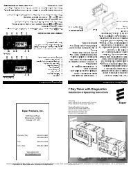
147 Day Timera - Power from battery “+”b - Switch control to heaterc - Power from battery “-”d - Diagnostics from heatere - Temperature setting “+”f - Temperature setting “-”g - Vehicle dimmer switch for light displayh - Vehicle ignition accessories for continuous operation of heater<strong>Heater</strong> OperationSwitch OnWarning:To prevent fire, the heater must beswitched off while filling fuel tanks.To prevent asphyxiation, the heatermust not be operated in enclosed areas• Switch the heater on using the room thermostat’s,On/Off switch (1=On, 0=Off ) or the rheostat switch.Start UpOn start up the indicator light illuminates and the followingsequences take place:Temperature Control• The temperature is monitored constantly at the heaterintake or thermostat.• This temperature is compared to the set temperatureon the adjusting dial.• The heater cycles through Boost, High, Medium andLow heat modes to maintain the desired temperature.• If the desired temperature is exceeded while the heateris operating in low heat mode the heater will switch off.This is a comfort feature.• The heater will re-start in medium heat mode once heatis again required.• Control unit does a systems check (glow plug, flamesensor, temperature sensor, safety thermal sensor).• Blower starts slowly and begins to accelerate.• Glow plug is energized and starts preheating the combustionchamber.• After a short delay (approximately 15 seconds) the fuelpump delivers fuel.• Ignition will take place as the fuel/air mixture contactthe glow plug.• Blower speed and fuel delivery are slowly increased.• Once flame is established the glow plug will switch off.• <strong>Heater</strong> will begin heating.Temperature SettingUsing the adjusting dial, set the desired temperature range.From 1-4• Lowest Setting - approx. 10°C (50˚F)• Mid - Setting - approx. 18°C (65˚F)• Highest Setting - approx. 30°C (85˚F)HighLowOperatingindicatinglightSwitch OffOnce switched off either manually or automatically, theheater begins a controlled cool down cycle.• The fuel pump stops delivering fuel.• The glow plug is re-energized for a 15 second after-glow.• The blower continues to run for 3 minutes and automaticallyswitches off.Controls and Safety Equipment• If the heater fails to ignite within two 90 second startattempts, a "no start" shut down occurs.• If a flame out occurs after the heater has started, theheater will attempt to restart.• If repeated flame outs occur within 10 minutes theheater will not restart.• Overheat shut down will occur if there is a restriction ofthe heating air flow (i.e. blocked inlet or outlet). Theoverheat switch will automatically reset once the heaterhas cooled down. Once the air flow restriction isremoved, the heater can be re-started by switching theheater off then back on.• If the voltage drops below 10.5 volts or rises above15.9 volts the heater will shut down (21volts and 30volts for 24 volt systems).• If the glow plug circuit or fuel metering pump circuit areinterrupted the heater will not start.• The blower motor is checked on start up and every 4minutes. Shut down will occur if the blower does notstart or maintain proper speed.www.westfaliat4.info - A useful information site for owners and enthusiasts of VW Westfalia T4 Campers
15Operational Flow Chartwww.westfaliat4.info - A useful information site for owners and enthusiasts of VW Westfalia T4 Campers
16Wiring Diagram<strong>D3LC</strong>compactGlow plug positive pulsedModels:25 1980 05 (12v)25 1981 05 (24v)www.westfaliat4.info - A useful information site for owners and enthusiasts of VW Westfalia T4 Campers
17Wiring Diagram<strong>D3LC</strong>compactGlow plug positive pulsedwith current regulatorModels:25 1967 05 (12v)25 1968 05 (24v)www.westfaliat4.info - A useful information site for owners and enthusiasts of VW Westfalia T4 Campers
18Wiring Diagram<strong>D3LC</strong>compactGlow plug negative pulsedModels:25 1906 05 (12v)25 1907 05 (24v)www.westfaliat4.info - A useful information site for owners and enthusiasts of VW Westfalia T4 Campers
20Self DiagnosticsThe heater is equipped with self diagnostic capability. Toretrieve information on the heaters last 5 faults, a retrievaldevice is required (part # CA1 05 020).Connect the fault code retrieval device as shownEquipment Face and ControlsSymbols that are seen on the display face are as follows:AFF1-F5Actual fault.Up to five stored faults can be accessed.The AF and F1 are the same number.This sign is displayed when the heater isin operation.DIAGThe word (Diagnostic) will come on whenthe diagnostic number is requested.000 Three digit diagnostic fault code number.On/OffRetrieval DeviceP/N: CA1 05 020Retrieval DeviceP/N: CA1 05 020• Switch the fault code retrieval device on and wait 10seconds.• Press the "D" button.• Wait 3-5 seconds for the current fault code to appear(AF).• To review the previous faults use the arrow buttons(F1= Most Recent, F5= Oldest).• To erase the faults that are in memory press both "L"keys at the same time.• Consult the fault code chart for code number descriptions.www.westfaliat4.info - A useful information site for owners and enthusiasts of VW Westfalia T4 Campers
24Fuel Quantity TestThe fuel quantity should be tested if the heater has difficultystarting or maintaining a flame:Preparation• Detach the fuel line from the heater.• Insert the fuel line into a measuring glass (20 cm 3size).• Switch the heater on and allow fuel system to bleed outair for approx. 25 seconds.• Switch the heater off and empty the measuring glass.Component Specification ChartComponent values given are reference numbers only(at room temperature). Actual component values mayvary ±10%.Motor SpeedsBoost4,200 RPMHigh4,200 RPMMedium 2,200 RPMLow3,000 RPMRecirculation 1,000 RPM (when using internaltemperature sensor)0 RPM when using externaltemperature sensor)Resistance ValuesMetering pump 12VMetering pump 24VGlow Plug 12VGlow Plug 24VOperating control/setpint pot.approx. 10Ωapprox. 36Ωapprox. 0.6 Ωapprox. 2 Ω1740-2180 Ω (±80Ω)Exhaust GasMeasurement• Switch heater on.• Hold the fuel line in the measuring glass while fuel isbeing delivered. Hold the graduated measuring glass atglow plug height during measurement• The pump will stop automatically after delivering fuelfor 90 seconds.• Once fuel pump stops, switch heater off. A restart willoccur if heater is not shut off.Evaluation• CO2 concentration in exhaust gas when heater is runningin High heat mode 9-11%.• Smoke test value from exhaust gas when heater isrunning in High heat mode
26<strong>Heater</strong> Casing Disassembly• Remove internal hex screw and cap.• Pry off air outlet hood using a flat screw driver.• Remove rivets by punching center pin through and pryingout base.• Remove rubber seal at base of heat exchanger.• Separate outer casing.• Re-assemble in reverse order using new rivets.1. Outer Casing2. Air Outlet Hood3. Cap with Internal Hex ScrewOverheat SensorFlame Sensor• Release Duo-Clip locking devices with a screw driverand detach insulating brackets.• Use new locking devices when installingOverheat Sensor Replacement• Using a small flat screw driver, pry off holding clips.• Lift sensor from mounting studs.• Install replacement sensor using new holding clips.• Ensure the sensor is securely mounted against heatexchanger.www.westfaliat4.info - A useful information site for owners and enthusiasts of VW Westfalia T4 Campers
27Flame Sensor Replacement• Using a small flat screw driver, pry off holding spring.• Remove spring and flame sensor.• Install replacement sensor using a new mounting spring.• Ensure the sensor is securely mounted against heatexchangerAir Blower1. Blower2. Heat Exchanger3. Gasket• Remove four mounting screws.• Separate blower from heat exchanger.• Re-assemble using new gasket.132Heat Exchanger• Remove two mounting screws and baffle plate.• Remove and replace gasket.• Clean excessive carbon from inside heat exchangerusing a brass wire brush, varsol and compressed air.• Inspect felt ring and replace if damaged.• Re-assemble in reverse order using new gaskets.1. Baffle Plate2. Gasket3. Seal Ring123www.westfaliat4.info - A useful information site for owners and enthusiasts of VW Westfalia T4 Campers
28Parts Diagram<strong>D3LC</strong>compactwww.westfaliat4.info - A useful information site for owners and enthusiasts of VW Westfalia T4 Campers
www.westfaliat4.info - A useful information site for owners and enthusiasts of VW Westfalia T4 Campers29
30www.westfaliat4.info - A useful information site for owners and enthusiasts of VW Westfalia T4 Campers
www.westfaliat4.info - A useful information site for owners and enthusiasts of VW Westfalia T4 Campers31
32Parts List<strong>D3LC</strong>compact<strong>Heater</strong> modelRef.DescriptionNo.Part Number1 Heat exchanger 25 1882 06 00 00 • • • • • •2 Combustion air blower 12 Volt 25 1906 99 20 00 • • •24 Volt 25 1907 99 20 00 • • •3 Flame sensor 25 1895 99 35 00 • • • • • •4 Safety thermal sensor 25 1895 41 00 00 • • • • • •*includes cable section5 Lower half of casing 25 1822 01 01 00 • • • • • •6 Upper half of casing 25 1906 01 06 00 • • • • • •7 Control unit 12 Volt 25 1895 50 00 03 • •24 Volt 25 1896 50 00 02 • •12 Volt 25 1976 51 00 03 •24 Volt 25 1977 51 00 02 •* If replacing the contol unit on heater models 25 1906 and 25 1967to the latest control unit 12 Volt 25 1976 51 00 03 you must replace themain heater harness with the p/n. CA1 60 120 harness or follow the conversioninstructions provided with the control unit to modify the existing harness* If replacing the contol unit on heater models 25 1907 and 25 1968to the latest control unit 24 Volt 25 1977 51 00 02 you must replace themain heater harness with the p/n. CA1 60 120 harness or follow the conversioninstructions provided with the control unit to modify the existing harness8 Flange seal 25 1822 01 00 02 • • • • • •9 Cable cover 25 1895 01 02 00 • • • • • •10 Glow plug 12 Volt 25 1830 01 01 00 • • •24 Volt 25 1831 01 01 00 • • •11 Seal ring 25 1830 01 01 01 • • • • • •12 Glow plug screen 25 1822 06 04 00 • • • • • •13 Gasket, blower 25 1822 01 00 03 • • • • • •14 Gasket, heat exchanger 25 1822 06 00 02 • • • • • •15 Seal ring, heat exchanger 25 1862 06 00 03 • • • • • •16 Spring, flame sensor 25 1895 01 00 03 • • • • • •17 Clip 171 42 082 • • • • • •18 <strong>Heater</strong> bracket 25 1822 01 00 04 • • • • • •19 Grub screw M6x20 DIN 835 106 10 022 • • • • • •20 Fillister head bolt M5x20 103 10 461 • • • • • •21 U-Clip 25 1688 01 00 03 • • • • • •22 Rivet, black plastic 131 31 051 • • • • • •23 Fillister head bolt M3x10 25 1822 01 00 05 • • • • • •24 Gasket 25 1822 80 09 01 • • • •25 Cable connection 25 1895 01 03 00 • • • •26 Tapit Screw M5x16 109 00 044 • • • • • •27 Mounting plate with hardware & seal CA0 00 019 • • • • • •28 Angle bracket 20 1348 03 00 02 • • • • • •29 Rubber mount 20 1673 80 01 01 • • • • • •29a Rubber mount 6mm 20 1185 00 00 01 • • • • • •30 Clamp for fuel metering pump 152 00 144 • • • • • •31 Plastic fuel line 1.5mm ID 090 31 118 • • • • • •www.westfaliat4.info - A useful information site for owners and enthusiasts of VW Westfalia T4 Campers
33<strong>Heater</strong> modelRef.DescriptionNo.Part Number31a Fuel hose 360 75 300 • • • • • •32 Fuel hose 360 75 350 • • • • • •33 Plastic fuel line 2mm ID 090 31 125 • • • • • •34 Fuel metering pump 25 1830 45 00 00 • • •25 1831 45 00 00 • • •35 Fuel screen 20 1312 00 00 06 • • • • • •36 Hose connection 20 1621 45 00 00 • • • • • •37 Rubber boots 320 31 120 • • • • • •38 Terminals 18 AWG - fuel metering pump CA1 90 060 • • • • • •39 Main Harness CA1 60 105 • •CA1 60 107 • •CA1 60 120 • •*40 Fuel pick up pipe (Compression fitting type) CA0 12 042 • • • • • •*41 Compression fittings 1/4” NPT CA0 12 044 • • • • • •3/8” NPT CA0 00 031 • • • • • •1/2” NPT CA0 12 005 • • • • • •42 Standard fuel pick up pipe 2mm CA0 12 056 • • • • • •43 Flat plug connector CA1 90 006 • • • • • •44 Connector housing 206 31 009 • • • • • •45 Socket housing 206 31 301 • • • • • •46 Socket connections 206 52 120 • • • • • •47 Grommet 20 1280 09 01 03 • • • • • •48 Tie clips 197mm CA1 00 005 • • • • • •49 "C" Clamp 10mm 152 00 139 • • • • • •50 Current regulator 25 1966 30 01 00 •25 1830 30 01 00 •51 Clamp 9mm 10 2063 00 90 98 • • • • • •52 Clamp 11mm 10 2063 01 10 98 • • • • • •53 Blade Fuse (25amp) 204 00 089 • • • • • •54 Fuse holder with terminals CA1 07 001 • • • • • •55 Terminals CA1 90 043 • • • • • •*56 Plastic Screen 75mm 25 1729 89 00 05 • • • • • •*57 Flange for outlet grill 25 1226 89 00 12 • • • • • •*58 Clamp 52mm-82mm CA1 10 041 • • • • • •59 Safety screen 75mm 25 1552 05 01 00 • • • • • •60 Outlet hood 75mm 25 1822 80 01 00 • • • • • •61 Clamp 3 inch(75mm) CA1 10 041 • • • • • •Clamp 4 inch(100mm) CA1 10 042 • • • • • •62 Flexible air hose 75mm 10 2114 34 00 00 • • • • • •63 Deflector 75/100mm 22 1050 89 21 00 • • • • • •*64 90° Air outlet hood 22 1000 01 00 03 • • • • • •65 C clamp 152 10 051 • • • • • •66 Flexible exhaust hose 25 1774 80 01 00 • • • • • •www.westfaliat4.info - A useful information site for owners and enthusiasts of VW Westfalia T4 Campers
34<strong>Heater</strong> modelRef.DescriptionNo.Part Number67 Clamp 26mm 152 61 102 • • • • • •68 Clamp 10 2064 02 00 32 • • • • • •69 Air intake silencer 20 1451 01 01 00 • • • • • •70 C clamp 152 10 047 • • • • • •71 End sleeve with cross bar 25 1729 89 00 02 • • • • • •*72 Fibre ring adapter 90mm- 4” (Wooden) CA2 02 002 • • • • • •90-100mm (Plastic) 20 1602 80 00 01 • • • • • •73 End sleeve with cross bar 25 1729 80 06 00 • • • • • •74 Switch/ Thermostat harness (15’) CA1 70 111 • • • • • •75 Fuel metering pump harness (20’) CA1 75 015 • • • • • •76 Power harness (13’) CA1 65 106 • • • • • •77 Thermostat 12 Volt 301 00 154 • • •24 Volt 301 00 153 • • •*78 Operating switch (rotary) 12 Volt 25 1895 71 00 00 • • •24 Volt 25 1896 71 00 00 • • •*79 7 day timer 22 1000 30 40 00 • • • • • •80 3/8” Ring terminal 10-12G CA1 90 014 • • • • • •81 Plug and socket connector 206 00 040 • • • • • •82 Terminals CA1 900 21 • • • • • •83 <strong>D3LC</strong>c North American manual (not shown) 610 102 1298 • • • • • •*84 Fault code retrieval device (shown pg. 20) CA1 05 020 • • • • • •* indicates optional featureswww.westfaliat4.info - A useful information site for owners and enthusiasts of VW Westfalia T4 Campers
Service History NotesSerial N°:________________________Date installed:_______________________Model N°:________________________DateService Detailswww.westfaliat4.info - A useful information site for owners and enthusiasts of VW Westfalia T4 Campers
1st. Printing - November <strong>1998</strong>Printed in CanadaP/N: 610-102-1298Espar Products, Inc.6435 Kestrel RoadMississauga, OntarioCanada L5T 1Z817672 N. Laurel Park DriveSuite 400ELivonia, MichiganUnited States48152-3984Canada (Tel): 905-670-0960800-668-5676Fax: 905-670-0728U.S. (Tel): 800-387-4800A member of the Worldwide Eberspächer GmbH Group of Companieswww.westfaliat4.info - A useful information site for owners and enthusiasts of VW Westfalia T4 Campers