GFK-160A Blower System - Heatilator Fireplaces
GFK-160A Blower System - Heatilator Fireplaces
GFK-160A Blower System - Heatilator Fireplaces

You also want an ePaper? Increase the reach of your titles
YUMPU automatically turns print PDFs into web optimized ePapers that Google loves.
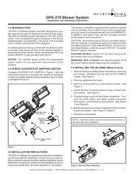
4.2 INSTALLING THE BLOWERPosition the blower all the way to the rear and centerin the fireplace. Pull the blower forward 1/8" to1/4" from the back wall of the fireplace (Figure 3).Thread blower cord plug through hole on bottom of cordbracket and plug into blower receptacle labeled "FAN" onpower cord.POWER CORD STYLE JUNCTION BOXPOWER CORD4.3 INSTALLING THE SPEED CONTROLAND SENSOR SWITCHIf using a remote control system that utilizes fancontrol, disregard steps 1-3 and follow remote controlinstallation instructions.1. Remove the knob and locknut from the variable speedcontrol. Slide the control behind the fi replace wall, inthe lower right front corner, with the stem sticking outof the pre-punched hole. Attach the locknut tightly andreattach the knob on the stem. Turn the speed controlswitch to the "ON" position.SENSOR SWITCHNOTE: Some models may have a separate mountinglocation on the base pan or valve bracket formounting this speed control.NOTE: SOME MODELS MAY HAVEA SEPARATE MOUNTING LOCATIONON THE BASE PANE OR VALVEBRACKET FOR MOUNTING THISSPEED CONTROL.BLOWERSPEED CONTROL2. Slide the temperature sensor switch/bracket assemblyonto the weld stud on the outside of the combustionchamber. Secure the bracket assembly with the wingnut provided. See Figure 4.NOTICE: The weld stud is located either on the lower rightside or the bottom of the combustion box.TEMPERATURESENSOR SWITCH1/8” TO 1/4”FIREPLACEWALLBLOWERSPEEDCONTROLWINGNUTPOWER STRIP STYLE JUNCTION BOXFigure 3BLOWERSENSORSWITCH“FAN”RECEPTACLESPEEDCONTROLFigure 4NOTICE: The switch/bracket assembly must be installedso that the sensor switch is facing the combustion boxsurface.3. Connect the variable speed control and the temperaturesensor switch to the junction box with the wires provided.See Figure 5 for the wiring diagram that matches thestyle of junction box on the fi replace.4. Turn the 110-120 VAC service "ON" at the circuitbreaker.2 Hearth & Home Technologies • <strong>GFK</strong>-<strong>160A</strong> <strong>Blower</strong> <strong>System</strong> Installation Instructions • 107-981 Rev P • 9/12