5700 WOOD STOVE - Hearth & Home Technologies
5700 WOOD STOVE - Hearth & Home Technologies
5700 WOOD STOVE - Hearth & Home Technologies
- No tags were found...

You also want an ePaper? Increase the reach of your titles
YUMPU automatically turns print PDFs into web optimized ePapers that Google loves.
RR<strong>5700</strong> ACT Wood Stoveand Welcome to the Quadra-Fire Family!<strong>Hearth</strong> & <strong>Home</strong> <strong>Technologies</strong> welcomes you to our traditionof excellence! In choosing a Quadra-Fire appliance, you haveour assurance of commitment to quality, durability, and performance.This commitment begins with our research of the market,including ‘Voice of the Customer’ contacts, ensuring we makeproducts that will satisfy your needs. Our Research and Developmentfacility then employs the world’s most advanced technologyto achieve the optimum operation of our stoves, inserts andfireplaces. And yet we are old-fashioned when it comes to craftsmanship.Each unit is meticulously fabricated and surfaces arehand-finished for lasting beauty and enjoyment. Our pledge to qualityis completed as each model undergoes a quality control inspection.We wish you and your family many years of enjoyment in thewarmth and comfort of your hearth appliance. Thank you for choosingQuadra-Fire.SAMPLE OF SERIAL NUMBER / SAFETY LABELLOCATION: On right side of insert as face the applianceHOT WHILE IN OPERATION DO NOT TOUCH, KEEP CHILDREN AND CLOTHING AWAY. CONTACT MAY CAUSE SKIN BURNS. KEEPCAUTION: FURNISHINGS AND OTHER COMBUSTIBLE MATERIAL FAR AWAY FROM THE APPLIANCE. SEE NAMEPLATE AND INSTRUCTIONSCHAUD LORS DE L'OPÉRATION. NE PAS TOUCHER. GARDEZ LES ENFANTS ET LES VÊTEMENTS LOIN DE L'ESPACE DÉSIGNÉ DE L'INSTALLATION. LE CONTACTATTENTION: PEUT CAUSER DES BRÛLURES À LA PEAU. GARDEZ LES MEUBLES ET LES MATÉRIAUX COMBUSTIBLES LOIN DE L'ESPACE DÉSIGNÉ DE L'APPAREIL. VOIRL'ÉTIQUETTE ET LES INSTRUCTIONS.LISTED ROOM HEATER, SOLID FUEL TYPE.ALSO FOR USE IN MOBILE HOMES. (UM)84-HUD . "For Use with Solid Wood Fuel Only"PREVENT HOUSE FIRESInstall and use only in accordance withmanufacturer's installation and operatinginstructions. Contact local building or fire officialsabout restrictions and installation inspections inyour area. Do not obstruct the space beneathheater.WARNING - For Mobile <strong>Home</strong>s: Do not install ina sleeping room. An outside combustion air inletmust be provided and unrestricted while unit is inuse. The structural integrity of the mobile homefloor, ceiling and walls must be maintained. Thestove needs to be properly grounded to the frameof the mobile home. Components required formobile home installation: Outside Air Kit, PartNumber 831-1780.Refer to manufacturer's instructions and localcodes for precautions required for passingchimney through a combustible wall or ceiling andmaximum offsets.Inspect and clean chimney frequently - UnderCertain Conditions of Use, Creosote Buildup MayOccur Rapidly.Do not connect this unit to a chimney servinganother appliance.Optional Components: Optional Blower, Part831-1701.Electrical Rating: 115 VAC, 1.2 Amps, 60 Hz.Route power cord away from unit. Do not routecord over or in front of appliance.DANGER: Risk of electrical shock. Disconnectpower supply before servicing.Replace glass only with 5mm ceramic availablefrom your dealer.Do not use grate or elevate fire. Build wood firedirectly on hearth.Do not overfire - if heater or chimney connectorglows, you are overfiring.Operate only with the fuel loading door closed.Open only to add fuel to the fire.FLOOR PROTECTION:PROTECTION DU PLANCHER:Floor protector must be a 1/2 inch min. thickness, ("k" value =Le protecteur de plancher doit être d'un minimum de 1/2 inchd'épaisseur, ('k" value = .84) de matériel incombustible ou.84) non-combustible material or equivalent, extending beneathéquivalent, s'étendant du dessous de l'appareil de chauffageheater and to front/sides/rear as indicated on the diagramà l'avant, aux cotés et à l'arrière comme indiqué sur lebelow. Exception: Non-combustible floor protections mustdiagramme suivant. Exception: Les protectionsextend beneath the flue pipe when installed with horizontalincombustibles du plancher doivent s'étendre en dessous duventing and extend 2 inches (51mm) beyond each side.conduit de cheminée lorsqu'installées avec une ventilation àl'horizontale et s'étendre de 2 inches (51mm) de chaque côté.Fuel loading door16" from glass33-5/8”minimumManufactured by:Fabriqué par:4-3/16”3-3/16”8"USA44-9/16”minimum1445 N. Highway, Colville, WA 99114www.quadrafire.comAPPAREIL DE CHAUFFAGE DE PIÈCE, DE TYPE DECOMBUSTIBLE SOLIDE, POUR USAGE DANS LESMAISONS MOBILES. (UM) 84 HUD. "Pour Usage AvecBois Solide Seulement"PRÉVENTION DES FEUX DE MAISONInstallez et utilisez en accord avec les instructionsd'installation et d'opération du fabricant. Contactez lebureau de la construction ou le bureau des incendies ausujet des restrictions et des inspections d'installation dansvotre voisinage. Ne pas obstruez l'espace en dessous del'appareil.AVIS - Pour Les Maisons Mobiles: Ne pas installer dansune chambre à coucher. Un tuyau extérieur decombustion d'air doit être installé et ne doit pas êtreobstrué lorsque l'appareil est en usage. La structureintégrale du plancher, du plafond et des murs de lamaison mobile doit être maintenue intacte. L'appareil dechauffage doit être fixé à la charpente de la maisonmobile. Les composants requis pour l'installation desmaisons mobiles: Assemblage d'air extérieur, Numéro dePièce 831-1780.Référez vous aux instructions du fabricant et des codeslocaux pour les précautions requises pour passer unecheminée à travers un mur ou un plafond combustibles,et les compensations maximums.Inspectez et nettoyez la cheminée fréquemment. Souscertaines conditions, il se peut que la créosotes'accumule rapidement.Ne pas connecter cet appareil à une cheminée servant unautre appareil.Composants Optionnels: Ventilateur Optionnel, Pièce#831-1701.Puissance Électrique: 115 VAC, 1.2 Amps, 60 Hz.Éloignez le fil électrique de l'appareil. Ne pas faire passerle fil électrique au dessus ou en dessous de l'appareil.DANGER: Il y a risque de décharge électrique.Déconnectez le fil électrique de la prise de contact avantle service.Remplacez la vitre seulement avec une vitre céramiquede 5 mm disponible chez votre fournisseur.N'élevez pas le feu. Bâtissez le feu de bois directementsur l'âtre.Ne pas surchauffer. Si l'appareil de chauffage ou le tuyaude cheminée rougissent, vous surchauffez.Opérez l'appareil seulement lorsque la porte dechargement est fermée. Ouvrez la porte seulementlorsque vous devez ajouter des combustibles dans le feu.203mm(8")203mm (8")457mm (18")CANADA1083mm (42-5/8")min203mm(8")1387mm(54-9/16")minimumTested andBeavertonListed by O-T L Oregon USACOMNI-Test Laboratories, Inc.TESTED TO:/ TESTÉ À:Report / RapportUL 1482, ULC S627-93#061-S-38-2VENT SPECIFICATIONS:SINGLE WALL: Six inch (6 inches) (152mm) diameter, minimum 24 MSG black orblued steel connector pipe, with a listed factory-built UL103HT* Class "A" chimney,suitable for use with solid fuels, or a masonry chimney, and the referenced clearances.DOUBLE WALL: Six inch (6 inches) (152mm) diameter, listed double wall airinsulated connector pipe with listed factory-built UL103HT* Class "A" chimney, or amasonry chimney and the referenced clearancesMOBILE HOME: Use double wall pipe by Dura-Vent DVL, Selkirk Metalbestos DS orSecurity DL double wall connector pipe. Must be equipped with a spark arrestor.Apply double wall clearances below when installing unit.MINIMUM CLEARANCES TO COMBUSTIBLE MATERIALS:In Inches & (Millimeters)NOTE: All "A" , "C" and "F" Dimensions are to inside diameter of the flue collar.<strong>5700</strong> Step TopINSTALLATION: FULL VERTICAL OR HORIZONTAL WITH MINIMUM 2 FT VERTICAL OFF <strong>STOVE</strong> TOPINSTALLATION: ENTIÈREMENT VERTICALE OU HORIZONTALE AVEC 609mm VERTICAL MINIMUM DU HAUT DU POÊLEA B C D E F G HSINGLE WALL PIPE 12.5 (318) 8 (203) 25.5 (648) 15 (381) 2 (51) 13 (330) 45.5 (1156) 18 (457)**CONDUIT DU MUR SIMPLEDOUBLE WALL PIPE 9.5 (241) 5 (127) 25.5 (648) 15 (381) 2 (51) 13 (330) 45.5 (1156) 12 (305) CONDUIT DU MUR DOUBLEINSTALLATION: 90 o ELBOW OFF TOP OF <strong>STOVE</strong> THROUGH BACKWALLINSTALLATION: 90 o DU COURBURE AU DESSUS DE HAUT DU POÊLE A TRAVERS LE MUR ARRIEREDOUBLE WALL PIPE 9.5 (241) 5 (127) 25.5 (648) 15 (381) 2 (51) 13 (330) 45.5 (1156) 12 (305)SPÉCIFICATIONS DE LA VENTILATION:MUR SIMPLE: De six (6 inches) (152mm) de diamètre le connecteur de conduit deminimum d'acier noir ou bleu de minimum de 24MSG, avec une cheminée bâtit enusine UL103HT* de Classe "A", adéquate pour usage avec les combustions solides,ou une cheminée de briques, avec espaces libres référés.MUR DOUBLE: De six (6 inches) (152mm) de diamètre, le connecteur du conduitd'air isolé pour mur double avec une cheminée bâtit en usine UL103HT* de Classe"A:, ou une cheminée de briques, avec espaces libres alloués.MAISON MOBILE: Utiliser un conduit de mur double par Dura-Vent DVL, SelkirkMetalbestos DS ou Security DL. Doit être équipé d'un arrêt d'étincelle. Utiliser lesespaces libres pour mur double comme mentionné ci-bas.ESPACES LIBRES MINIMUM DES MATÉRIAUX COMBUSTIBLES:En Pouces & (millimètres)NOTE: Toutes les dimensions "A", "C", et "F" sont à partir du diamètre intérieurde l'entrée du conduit.INSTALLATION: ALCOVE - Six inch (6 inches) (152mm) diameter listed DOUBLE WALL air insulated connector pipe with UL103 HT* listed factory-builtClass "A" chimney, or a masonry chimney. (Mobile <strong>Home</strong> must be equipped with a spark arrestor.) Maximum depth of Alcove shall be no more than 48inches (1220mm) with a minimum height of 45.5 inches (1156mm) to top of unit, and the referenced clearances.INSTALLATION: ALCÔVE - De six (6 inches) (152mm) de diamètre, le connecteur du conduit d'air isolé pour mur double avec une cheminée bâtit en usineUL103HT de Classe "A", ou une cheminée de briques. (Les maisons mobiles doivent être équipées d'un arrêt d'étincelle). La profondeur maximum de l'alcôvene doit pas être de plus de 48 inches (1220mm) avec une hauteur minimum de 45.5 inches (1156mm) du haut de l'appareil, et des espaces libres alloués.(*In Canada must comply with Standard CAN/ULC-S629-M87 for the 650 o C Factory-built chimney.)(*Au Canada doit conformer a CAN/ULC-S629-M87 la norme pour 650 o C cheminée bâtit en usine.)DOUBLE WALL PIPE 10.5 (268) 6 (153) 25.5 (648) 15 (381) N/A N/A 45.5 (1156) CONDUIT DU MUR DOUBLE*****NFPA MINIMUM CLEARANCES - NOT TESTED*** SEE PIPE MANUFACTURERS CLEARANCES - NOT TESTEDALCOVE SIDE VIEW /VUE DE CÔTÉ DE L'ALCÔVEGABALCOVE TOP VIEW /VUE DU HAUT DE L'ALCÔVEBACKWALL/SIDEWALLMUR ARRIÈRE/MUR DE CÔTÉCORNER INSTALLATIONINSTALLATION DU COIN90 OFF TOPUP & OUT CEILING CLEARANCEESPACE LIBRE DU DESSUS DEL'APPAREIL AU PLAFOND AVEC 90 DECOURBURE<strong>STOVE</strong> TO CEILING CLEARANCEESPACE LIBRE DU POÊLE AU PLAFOND2007 2008 2009 Jan. Feb. Mar. Apr. May June July Aug. Sept. Oct. Nov. Dec. U.S. ENVIRONMENTAL PROTECTION AGENCY - Certified tocomply with July 1990 particulate emission standards.250-7072EDO NOT REMOVE THIS LABEL / NE PAS ENLEVER L'ÉTIQUETTEMade in U.S.A./Fait Aux États-UnisCD"G" is from topwhere flue isconnectedGCONDUIT DU MUR DOUBLEHSERIAL NO. / NUMÉRO DE SÉRIE007AEBFCDFESize: 8-1/2” x11Copy: Red & BlackBackground: SilverMaterial: Foil w/slit backSerialNumberModelNameTest Lab &Report No.Mfg DatePage 250-7090ESeptember 1, 2008
R<strong>5700</strong> ACT Wood StoveTABLE OF CONTENTSListings & Safety Cautions.............................................4Installation Materials Needed.........................................4Venting System Overview..............................................4Dimensions....................................................................5Locating Your Stove.......................................................5Serial Number Label Location........................................6Clearances to Combustibles..........................................6Vent Specifications.........................................................7Floor Protection..............................................................7Alternate Materials Worksheet.......................................8INSTALLATION METHODS:Chimney Height / Draft & 2-10-3 Rule........................... 9Flue Systems & Chimney Connections.......................... 10Masonry Chimney..........................................................10Solid Pack with Metal Supports.....................................11-12Metal Pre-Fab Chimney.................................................13Mobile <strong>Home</strong>..................................................................14ACCESSSORY / PARTS REPLACEMENTAsh Removal System................................................... 15Pedestal & Leg Kit Installation..................................... 16Blower Installation........................................................ 17Outside Air Kit.............................................................. 17Brick Replacement....................................................... 23Glass Replacement...................................................... 23Door Handle Assembly................................................ 24Baffle & Ceramic Blanket Removal & Installation........ 24Accessory & Replacement Parts List........................... 25Exploded Views............................................................ 26Service & Maintenance Log......................................... 27-28<strong>Home</strong>owner’s Notes..................................................... 29Warranty Policy............................................................ 30-31Contact Information...................................................... 32OPERATING INSTRUCTIONS:Ash Removal System.....................................................15Burning Process.............................................................19Start-Up & Primary Air Systems.....................................192-Step Door Handle Instructions....................................19Operating Instructions....................................................20Building a Fire................................................................20Opacity...........................................................................21Burn Rates.....................................................................21Wood Selection..............................................................21Blower Operation...........................................................21MAINTENANCE:Creosote Removal.........................................................22Chimney Cleaning..........................................................22Ash Disposal .................................................................22Overfiring.......................................................................22Firebrick ........................................................................22Glass Care & Cleaning..................................................22Plated Surfaces..............................................................22September 1, 2008250-7090EPage
R<strong>5700</strong> ACT Wood StoveThese installation instructions describe the installation and operationof the QUADRA-FIRE <strong>5700</strong> woodstove. This stove meets theU.S. Environmental Protection Agency’s 1990 particulate emissionstandards. The <strong>5700</strong> is listed by OMNI-Test Laboratories, Inc. toUL Safety Standard 1482, and ULC S627-93, and (UM) 84-HUD.The <strong>5700</strong> is approved for mobile home installations when notinstalled in a sleeping room and when an outside combustionair inlet is provided. The structural integrity of the mobile homefloor, ceiling, and walls must be maintained. The stove must beproperly grounded to the frame of the mobile home and use onlylisted double-wall connector pipe. Outside Air Kit, Part 831-1780,must be installed in a mobile home installation.Check with your local building code agency before you begin yourinstallation to ensure compliance with local codes, including theneed for permits and follow-up inspections. Be sure local buildingcodes do not supersede UL specifications and always obtaina building permit so that insurance protection benefits cannot beunexpectedly cancelled. If any assistance is required during installation,please contact your local dealer.Inspect and clean vent system frequently in accordance with theinstructions contained in this manual. Do not connect this unit toa chimney serving another appliance.When using optional Blower, Part 831-1701, route power cord awayfrom unit. Do not route cord under or in front of appliance.Do not elevate fire. Build wood fire directly on firebrick.Do not overfire - if heater or chimney connector glows, you areoverfiring. Stove thermometer recommended.Operate only with the door closed. Open only to add fuel to thefire. Operating with the door open can cause hot embers or sparksto fall out and a fire may result.INSTALLATION MATERIALS NEEDED FOR SAFETYCHIMNEY CONNECTOR (also known as flue pipe or stove pipe):The chimney connector joins the stove to the chimney (see page9). It must be 6” (152mm) minimum diameter 24 MSG black orblued steel, or an approved air-insulated double wall ventingpipe.LISTINGS & SAFETY CAUTIONSFIRE SAFETY: To provide reasonable fire safety, the following shouldbe given serious consideration:1. Install at least one smoke detector on each floor of your hometo ensure your safety. They should be located away from theheating appliance and close to the sleeping areas. Followthe smoke detector manufacturer’s placement and installationinstructions, and be sure to maintain regularly.2. A conveniently located Class A fire extinguisher to contend withsmall fires resulting from burning embers.3. A practiced evacuation plan, consisting of at least two escaperoutes.4. A plan to deal with a chimney fire as follows:In the event of a chimney fire:a. Immediately evacuate the home.b. Notify fire departmentVENTING SYSTEMThe venting system consists of a chimney connector and a chimney.These get extremely hot during use. Temperatures inside thechimney may exceed 2000°F (1100°C) in the event of a creosotefire. To protect against the possibility of a house fire, the chimneyconnector and chimney must be properly installed and maintained. Anapproved thimble must be used when a connection is made through acombustible wall to a chimney. A chimney support package must beused when a connection is made through the ceiling to a prefabricatedchimney. These accessories are absolutely necessary to provide safeclearances to combustible wall and ceiling material. Follow ventingmanufacturer’s clearances when installing venting system.This stove may be connected to a lined masonry chimney or a Listedhigh temperature prefabricated approved metal chimney. Do notconnect it to a chimney serving another appliance. To do so will affectthe safe operation of both appliances.THIMBLE: A manufactured or site-constructed device installed incombustible walls through which the chimney connector passes tothe chimney (see pages 12-13). It is intended to keep the wallsfrom igniting.CHIMNEY SYSTEMS:A. APPROVED MASONRY (see specifications on page 10)with at least 5/8” (16mm) fire clay lining joined with refractorycement or other listed system suitable for use with woodstoves.B. PREFABRICATED 6" (152mm) listed high temperature (UL103 HT or ULC S629M) chimney. Components required bymanufacturers for installation such as the chimney supportbase, firestop (as appropriate), attic insulation shield, insulatedtee, etc., are necessary to assure a safe chimney installation.Use only components manufactured for the chimney. Chimneyinstallation should meet NFPA 211 standards.WARNING! NEVER DRAW OUTSIDE COMBUSTION AIR FROM AWALL, FLOOR OR CEILING CAVITY OR FROM ANY ENCLOSEDSPACE SUCH AS AN ATTIC OR GARAGE.WARNING! DO NOT ATTEMPT TO OPERATE THIS <strong>WOOD</strong><strong>STOVE</strong>WITHOUT READING AND UNDERSTANDING THESE OPERAT-ING INSTRUCTIONS THOROUGHLY. FAILURE TO OPERATETHIS APPLIANCE PROPERLY MAY CAUSE A HOUSE FIRE.WARNING! THIS APPLIANCE IS HOT WHILE IN OPERATIONAND MAY REMAIN SO UP TO 40 MINUTES AFTER THERE ISNO FUEL IN THE FIREBOX. IF THIS APPLIANCE IS IN A HIGHTRAFFIC AREA OR CHILDREN MAY BE NEAR IT IS RECOM-MENDED THAT YOU PURCHASE A DECORATIVE BARRIOR TOGO IN FRONT OF THE APPLIANCE. always keep childrenaway while it is operating and do not let anyoneoperate this appliance unless they are familiarwith these operation instructions.Page 250-7090ESeptember 1, 2008
R10-1/16"(256mm)26-5/8" (676mm)C L13-5/16"(338mm)DIMENSIONS<strong>5700</strong> ACT Wood Stove33-1/16" (840mm)30-1/4" (768mm)17.0" (768mm)38-3/4"(984mm)17-1/8" (494mm)21-1/16" (535mm)11.0"(279mm)14-15/16"(379mm)back of stove to glass29-3/16" (742mm)19-7/16" (494mm)21-9/16"(548mm)13-11/16"(348mm)24.0" (610mm)26-5/8" (676mm)4-1/2"(114mm)C L7-1/4"(184mm)4.0"(102mm)35-1/2"(902mm)19-15/16" (506mm)4-3/16" (106mm)26-11/16" (678mm)Shown with Ash Removal System AccessoryLOCATING YOUR <strong>STOVE</strong>8-9/16"(217mm)26-15/16" (684mm)10-7/16"(265mm)When locating your stove consider safety, convenience, traffic flow, and the fact that the stove will need a chimneyand chimney connector. It is a good idea to plan your installation on paper, using exact measurements for clearances andfloor protection, before actually beginning the installation. If you’re not using an existing chimney, place the stove wherethere will be a clear passage for a factory-built listed chimney through the ceiling and roof.AVOID FIRE: Maintain the designated clearances to combustibles. Insulation must not touch the chimney. You must maintainthe designated air space clearance around the chimney. This space around a chimney is necessary to allow natural heatremoval from the area. Insulation in this space will cause a heat buildup, which may ignite wood framing. NOTE: Clearancesmay only be reduced by means approved by the regulatory authority having jurisdiction.We recommend that a qualified building inspector and your insurance company representative review yourplans before and after installation.September 1, 2008250-7090EPage
R<strong>5700</strong> ACT Wood StoveCLEARANCES TO COMBUSTIBLES (UL AND ULC)BACkWALL / SIDEWALLAbCD90° OFF TOPUP & OUT CEILINGCLEARANCEgH*ALCOVE SIDE VIEWgAB<strong>STOVE</strong> TO CEILINGCLEARANCECORNER INSTALLATIONeFALCOVE TOP VIEWCeDFMINIMUM CLEARANCES TO COMBUSTIBLE MATERIALS In Inches and (Millimeters)NOTE: All “A”, “C” and “F” Dimensions are to the inside diameter of the flue collar.A b C D e F g HINSTALLATION: Full Vertical OR Horizontal with 2 foot minimum vertical Off Stove TopSINGLE WALL PIPE 12.5 (318) 8 (203) 25.5 (648) 15 (381) 2 (51) 13 (432) 45.5 (1156) 18 (457)*DOUBLE WALL PIPE 9.5 (241) 5 (127) 25.5 (648) 15 (381) 2 (51) 13 (432) 45.5 (1156) 12 (305)INSTALLATION: 90 o ELBOW OFF TOP OF <strong>STOVE</strong> THROUGH BACkWALLDOUBLE WALL PIPE 9.5 (241) 5 (127) 25.5 (648) 15 (381) 2 (51) 13 (432) 45.5 (1156) 12 (305)INSTALLATION: ALCOVE Six inch (6") (152mm) diameter listed Double Wall air insulated connectorpipe with UL103 HT listed factory-built Class "A" chimney, or a masonry chimney. (Mobile <strong>Home</strong>must be equipped with a spark arrestor). Maximum depth of Alcove shall be no more than48"(1220mm) with a minimum height of 45.5" (1156mm) to top of unit, and the referencedclearances.DOUBLE WALL PIPE 10.5 (268) 6 (153) 25.5 (648) 15 (381) N/A N/A 45.5 (1156) *** NFPA MINIMUM CLEARANCES - NOT TESTED** SEE PIPE MANUFACTURERS CLEARANCES - NOT TESTEDSERIAL NUMBER / SAFETY LABEL LOCATION:ON BACK OF <strong>STOVE</strong>Page 250-7090ESeptember 1, 2008
R<strong>5700</strong> ACT Wood StoveFLOOR PROTECTIONFLOOR PROTECTION: Floor protector must be non-combustible material, extending beneath heater and to the front/sides/rearas indicated. The floor must be non-combustible or otherwise adequately protected from radiant heat given off by the unit andfrom sparks and falling embers. A layer of thin brick or ceramic tile over a combustible floor is not sufficient. A listed hearth padthat has a “k” value of .84 or lower meets this requirement.In US installations, it is necessary to install a floor protector of 1/2" thick metal clad millboard (“k” value = .84) or equivalent atleast 16" (457mm) in front of glass door and 8" (203mm) to both sides of the fuel loading door. Open the door and measure 8”(203mm) from the side edge of the opening in the face of the stove. See *exception below.See Alternate Materials Worksheet on Page 8 to determine if alternate floor protection materials are acceptable.In Canada, similar floor protection must be provided 18" (457mm) in front and 8" (203mm) from the sides and rear of thestove. See *exception below.*Exception: Non-combustile floor protection must extend beneath the flue pipe when installed with horizontal ventingand extend 2” (51mm) beyond each side.NOTE: Drawings are for illustration purposes only and are not to scale.52-13/16 in.3-3/16"Fuel loading door4-13/16"44-9/16"minimum33-5/8 in.optionalcoverage135°32-1/16 in.16" from glass8"USA44-7/8 in.29-5/16 in.3-1/16 in.USA33-5/8"minimum203mm (8")203mm(8")203mm(8")1387mm(54-9/16")minimum457mm (18")USACANADAmust extend 2" beyond each side of pipe1083mm (42-5/8")minimumUSA - RequiredCanada - RecommendedVent SpecificationsSingle Wall: Six inch (6”) (152mm) diameter, minimum 24 MSG black or blued steel connector pipe, with a Listed factory-builtchimney type UL103 HT* suitable for use with solid fuels, or a masonry chimney, and the referenced clearances.Double Wall: Six inch (6”) (152mm) diameter, listed double wall air insulated connector pipe with Listed factory-built UL103 HT* Class“A” chimney, or a masonry chimney (Mobile <strong>Home</strong> must be equipped with a spark arrestor), and the referenced clearances.*In Canada must comply with CAN/ULC-S269-for the 650° C Factory-built chimneySeptember 1, 2008250-7090EPage
R<strong>5700</strong> ACT Wood Stovefigure 6FLUE SYSTEMSThere are two separate and different parts to a flue system: thechimney connector and the chimney itself.A. Single wall connector or stove pipe. This must be at least24 gauge mild steel or 26 gauge blue steel. The sectionsmust be attached to the stove and to each other withthe crimped (male) end pointing toward the stove. SeeChimney Connector Diagram below. All joints, includingthe connection at the stove collar, should be securedwith three sheet metal screws. Make sure to followthe minimum clearances to combustibles as set out onpage 6 of this manual. Where passage through the wall,or partition of combustible construction is desired, theinstallation shall conform to CAN/CSA-B365 (Canada).B. Factory-built listed chimney connector (vented). A listedconnector (vented) must be used when installing this unitin a mobile home. The listed connectors must conform toeach other to ensure a proper fit and seal.MASONRY CHIMNEY (Cont’d)The flue should be checked to determine that it is not toolarge for the stove. NFPA 211 allows the cross-sectionalarea of the flue to be no more than 3 times the crosssectionalarea of the flue collar of the stove (28 x 3 =84 square inches). It is recommended that a chimneywith a larger diameter than 6” (152mm) be relined,since the oversized flue can cause poor performanceand contribute to the accumulation of creosote. (Seepage 9 for more information about troubleshooting draftproblems).CAUTION! DO NOT CONNECT THIS UNIT TO A CHIMNEYFLUE SERVING ANOTHER APPLIANCE.When connecting the stove through a combustible wall toa masonry chimney, special methods are needed. Thereare several ways to make this connection, includingthe construction of a masonry thimble. In Canada, theinstallation shall conform to CAN/CSA-B365. Check withyour local building authorities and/or consult the NationalFire Protection Association (NFPA 211). Refer to Figure13B on page 13 and Figures 14A & 14B on page 14TOWARDS<strong>STOVE</strong>FLUEGASDIRECTIONWood Stud 2"(51mm)Clearancefrom chimneywallFireclay liner 5/8"(16mm) Minimumor equivalent.HeaderFIGURE 10A - Chimney ConnectorMASONRY CHIMNEYFor optimal performance, masonry chimneys used to vent thisappliance should be lined with a 6" (152mm) stainless steelliner. Installations into a clay flue without a stainless steel linermay reduce draw which affects performance, cause the glassto darken and produce excessive creosote.Ensure that a masonry chimney meets the minimum standardsof the National Fire Protection Association (NFPA) Standard211. It must have at least a 5/8" (16mm) fire clay liner or a listedchimney liner system. See Figure 11B on page 11. Make surethere are no cracks, loose mortar or other signs of deteriorationand blockage. It is best to have the chimney inspected by aprofessional, and be sure to have the chimney cleaned beforethe stove is installed and operated.Fireclay liner 5/8"(16mm) Minimumor equivalent.Sill supportFIGURE 10BThimble Assembly:12" (305mm) of brickseparation betweenclay liner andcombustibles.WARNING!! if installing this model to a masonry chimney, always be sure the chimney is in goodcondition and that it meets the minimum standards of the national fire protection association (NFPA)standard 211. A FACTORY BUILT CHIMNEY MUST BE 6” (152mm) UL103 HT.this appliance is made with a 6 inch (152mm) diameter chimney connector as the flue collar on theunit. changing the diameter of the chimney can affect draft and cause poor performance. it is notrecommended to use offsets or elbows at altitudes above 4000 feet above sea level or when thereare other factors that affect flue draft.Page 10250-7090ESeptember 1, 2008
R<strong>5700</strong> ACT Wood StoveSOLID PACK CHIMNEY WITH METAL SUPPORTS AS A THIMBLEFor the method of installation to a masonry chimney shown in Figures 13A & 13B on page 13, it will be necessary to purchasea 12” (305mm) long 8" (203mm) inside diameter, section of prefabricated Listed solid pack chimney to use as a thimble.Purchase a wall spacer, trim collar, and a wall band manufactured to fit the chimney section you purchase.The safety features of this system are two fold:1. A 2" (51 mm) air space between the chimney section and combustible wall2. The 1" (25mm) air space around the chimney connector as it passes through the chimney section to the chimney.The location of the opening through the wall to the chimney must leave a minimum 18" (457mm) vertical clearancebetween the connector pipe and the ceiling (or minimum recommended from pipe manufacturer) to prevent theceiling from catching fire.Measure for the center-line as shown in Figure 11A below. Cut an opening in the wall large enough to accommodate theoutside dimension of the chimney section plus the minimum air space specified by its manufacturer. It may be necessaryto cut the wall studs and install a header and a sill frame to maintain the wall support. The hole in the chimney must haveat least an 8" (203mm) diameter fire clay liner or equivalent, secured with refractory mortar. If it is necessary to cut a holein the chimney liner, use extreme care to keep it from shattering.CONCreTe CAPFIreCLAY FLUe LINerWITH AIr SPACeWallrAFTerCenter LineOpeningCenter of HoleCenter LineCeILINg JOIST1" (25mm)CLeArANCeWITH FIreSTOPFLASHINgeAVeCOMbUSTIbLe WALL1" (25mm) CLeArANCeTHIMbLe,12" (305mm)OF brICKSHeATHINgAdd center-line measurement todepth measurement of your floor protector.Mark this combined measurementat correct wall location for yourinstallation, maintaining minimumclearance to combustibles.FIGURE 11AFLOOr PrOTeCTOrFIGURE 11BAIrTIgHTCLeANOUT DOOrWARNING! always follow chimney connector manufacturer’s instructions for proper installation.chimney connector is to be used only within the room, between the stove and ceiling or wall, neverpassing through a combustible ceiling or wall. THE CONNECTOR SHALL NOT PASS THROUGH AN ATTIC ORROOF SPACE, CLOSET OR SIMILAR CONCEALED SPACE, OR A FLOOR, OR CEILING. MAINTAIN minimum clearancesto combustibles as REFERENCED on page 7.September 1, 2008250-7090EPage 11
R<strong>5700</strong> ACT Wood StoveSOLID PACK CHIMNEY WITH METAL SUPPORTS AS A THIMBLE (Cont’d)First, make the frame for the thimble, ensuring it is nosmaller than 14" (356mm) square, to maintain a 2"(51mm) air space around the chimney section.Min. Chimney Clearanceto Wall Spacer andCombustibles - 2" (51mm)Min. Clearance2" (51mm)Attach the wall spacer to the chimney side of theframe. Then insert the frame into the opening, toenailing it to the wall studs. Install the wall band in theframing to secure the chimney section in place.Insert a single section of chimney connector into thechimney through the wall band, being sure it doesnot protrude into the chimney beyond the edge ofthe chimney flue lining.Apply high temperature furnace cement to the end ofthe chimney section and install it over the connector,through the wall spacer. Tighten the wall band tohold the chimney section firmly in place and againstthe chimney.Chimney FlueLinerFireclayLiner orequivalentWall bandMasonry ChimneyWall SpacerConstructed to NFPA 211FIGURE 12A1" (25mm) AirSpace to ChimneySectionChimneyConnectorChimney SectionTrim CollarInstall the trim collar on the outside of the opening.Check to make sure there is a 1" (25mm) air spacebetween the connector and the chimney section.During installation be certain that a 2" (51mm) airspace to the wood framing is maintained. Do notfill this space with insulation. Insulation in this airspace will cause a heat buildup which may ignitethe wood framing.Trim CollarChimney Sectionwith 2" (51mm)Clearance toCombustiblesFire ClayFlue Linerwith AirspaceMasonryChimneyWall SpacerWall band toSecureChimneySectionFIGURE 12BChimneyConnectorWood Studs Used forFraming - Spaced 2"(51mm) clearancefrom MasonryChimneyPage 12250-7090ESeptember 1, 2008
R<strong>5700</strong> ACT Wood StoveCONNECTION TO A METAL PRE-FABRICATED CHIMNEYWhen a metal prefabricated chimney is used,the manufacturer’s installation instructionsmust be followed precisely. You must alsopurchase (from the same manufacturer)and install the ceiling support package orwall pass-through and “T” section package,firestops (where needed), insulation shield, roofflashing, chimney cap, etc. Maintain the properclearance to the structure as recommended bythe manufacturer. This clearance is usually aminimum of 2” (51mm), although it may vary bymanufacturer or for certain components.There are basically two methods of metalchimney installation. One method is to installthe chimney inside the residence through theceiling and the roof (Figure 13A). Install anattic insulation shield to maintain the specifiedclearance to insulation. Insulation in this airspace will cause a heat buildup which may ignitethe ceiling joists.The other method is to installan exterior chimney that runs up the outsideof the residence (Figure 13B). This methodof installation requires at a minimum a wallpass-through device, a wall support package,insulated “T” section and roof flashing. Thecomponents illustrated may not look exactly likethe system you purchase, but they demonstratethe basic components you will need for aproper and safe installation.The chimney must be the required heightabove the roof or other obstruction for safetyand proper draft operation. The chimneymust be a minimum of 3’ (91cm) higher thanthe highest point where it passes through theroof, and at least 2’ (61cm) higher than thehighest part of the roof or structure that iswithin 10’ (305cm) of the chimney, measuredhorizontally (2-10-3 Rule Figure on page9).ChimneyConnectorChimneyConnectorFloorProtectorMaintain 2" (51mm)ClearanceListed ChimneyCombustibleCeilingCeiling SupportMaintain 2" (51mm)Clearance Through eave**Listed CapStorm CollarFlashingFIGURE 13A - INTERIOR CHIMNEY**Listed CapFlashingCombustibleCeilingJoistsChimneyConnectorListedChimney PipeChimneyConnectorTo StoveTrim Collaron InsideWallInsulated " T "Combustible Wall* refer to Clearancesto CombustiblesListedChimneyTo StoveAtticInsulationShieldSpecifiedClearanceCeilingSupportCombustible Outside Wall2" (51mm)ClearanceWall Spacer onOutside WallListed ChimneyInsulated " T "Wall SupportIMPORTANT!Follow the manufacturer’sinstallation instructionsand maintain themanufacturer’s specifiedclearance distances.FloorProtectorCombustible Wall*refer to Clearances to CombustiblesFIGURE 13B - EXTERIOR CHIMNEYIn Canada when using a factory-built chimney, make sure it is safety listed, Type UL 103 HT CLASS "A"or conforming to CAN/ULC-S629, STANDARD FOR 650°C FACTORY-BUILT CHIMNEYS.September 1, 2008250-7090EPage 13
R<strong>5700</strong> ACT Wood StoveMOBILE HOME INSTALLATIONYou must use a Quadra-Fire Outside Air Kit for installation in a mobile home.1. An outside air inlet must be provided for combustion andmust remain clear of leaves, debris, ice and/or snow. Itmust be unrestricted while unit is in use to prevent roomair starvation which can cause smoke spillage and aninability to maintain a fire. Smoke spillage can also setoff smoke alarms.2. Stove must be secured to the mobile home structure bybolting pedestal through hearth pad and into floor. Forleg models, use 1/4” (6mm) lag bolts with the appropriatelength for your application.3. Stove must be grounded with #8 solid copper groundingwire or equivalent and terminated at each end with N.E.C.approved grounding device.4. Stove must be installed with an approved UL103 HTventilated chimney connector, UL103 HT chimney, andterminal cap with spark arrestor. Never use a single wallconnector (stove pipe) in a mobile home installation. Useonly double-wall connector pipe, Dura-Vent DVL, Selkirkmetalbestos DS or Security DL double-wall connector orany Listed double-wall connector pipe.5. Refer to page 6 of this manual or the Serial Number labelon the back of the stove for clearances to combustibles.6. Floor protection requirements on pages 7-8 must befollowed precisely.7. In Canada, this appliance must be connected to a 6”(152mm) factory-built chimney conforming to CAN/ULC-629M, STANDARD FOR FACTORY BUILT CHIMNEYS.8. Use silicone to create an effective vapor barrier at thelocation where the chimney or other component penetratesto the exterior of the structure.9. Follow the chimney and chimney connector manufacturer’sinstructions when installing the flue system for use in amobile home.NOTE: Offsets from the vertical, not exceeding 45°, areallowed per Section 905(a) of the Uniform MechanicalCode (UMC). Offsets greater than 45° are consideredhorizontal and are also allowed, providing the horizontalrun does not exceed 75% of the vertical height of thevent. Construction, clearance and termination must be incompliance with the UMC Table 9C.NOTE: Top sections of chimney must be removable to allowmaximum clearance of 13.5 ft (411cm) from ground levelfor transportation purposes.FloorProtectorFIGURE 14AStorm CollarJoist Shield/FirestopSpark Arestor Caproof FlashingDouble WallConnector PipeOutside AirKit ConnectorOutside AirFloor VentWARNING: NEVER DRAW COMBUSTION AIR FROMA WALL, FLOOR OR CEILING CAVITY OR FROMANY ENCLOSED SPACE SUCH AS AN ATTIC ORGARAGE.CAUTION: THE STRUCTURAL INTEGRITY OF THEMOBILE HOME FLOOR, WALL AND CEILING/ROOFMUST BE MAINTAINED. (i.e., DO NOT CUT THROUGHFLOOR JOIST, WALL STUD, CEILING TRUSS, ETC.)WARNING: DO NOT INSTALL IN SLEEPING ROOM.10. Burn wood only. Other types of fuels may generate poisonous gases (e.g., carbon monoxide).11. If unit burns poorly while an exhaust blower is on in home, (i.e., range hood), then increase combustion air.Page 14250-7090ESeptember 1, 2008
R<strong>5700</strong> ACT Wood StoveASH REMOVAL SYSTEM (ARS) INSTALLATION1. Place protective pad or stove pallet on floor.2. Lay body of stove on its back on protective pad or pallet.3. Remove ash removal system top and bottom cover plates byloosening nuts under stove. Discard both plates.STOVe bOTTOMFIGURE 15ATOP COVerPLATeNUTSgrATe4. Using a rubber mallet, install plugs (supplied) into two frontholes, See Figure 15B.5. Line up holes in ash removal system with holes in adapter onbottom of stove.6. Screw ash removal system securely in place.7. Insert ashpan into ash removal system box, making surethe overhanging lip is facing towards you.8. Attach legs or pedestal.CAUTION FOR NOTE LEG MODELS: DO NOT TILT THEUNIT ON THE CAST IRON LEGS. Lift the unit upright andplace it into position on the floor protector.9. After righting stove, insert ash removal system grate intoopening in firebox floor.ARS OPERATING AND CLEANING1. When stove is cool, open front door and brush mostof the ash into the center of the firebox. Rememberto leave 1/4” to 1/2” (6-13mm) of ash on the fireboxfloor to act as a natural grate, allowing air to flowfreely underneath wood.2. Clean ash down through the ash removal systemgrate into the drawer below. If there are large piecesin the ashes, you can remove the grate beforebrushing the ash into the drawer. Be sure to replacethe grate before operating the stove.3. Swing open ash removal door on leg model. (On thepedestal model, first pull down the hinged pedestalfront to expose the ash removal door).4. Pull out the ash drawer. CLOSE the ash removaldoor. (Closing this door avoids ash blowing into theroom in the event of a downdraft).5. Empty the ashes following the directions below.6. Swing open ash removal door and replace ashdrawer with the overhanging lip facing toward you.7. Close ash removal door securely.Disposal of Ashes. Ashes should be placed in a metalcontainer with a tight fitting lid. The closed container ofashes should be placed on a non-combustible floor oron the ground, well away from all combustible materials,pending final disposal. If the ashes are disposed of byburial in soil or otherwise locally dispersed, they shouldbe retained in the closed container until all cinders havethoroughly cooled.Ash DrawerDISCARDLEG MODELINSTALL PLUGSINTO THESE TWOHOLESAsh DrawerFIGURE 15bPEDESTAL MODELPull down pedestal front firstSeptember 1, 2008250-7090EPage 15
R<strong>5700</strong> ACT Wood StovePEDESTAL OR LEG KIT INSTALLATIONWARNING: DO NOT OPERATE <strong>STOVE</strong> BEFORE FULLY ASSEMBLING ALLCOMPONENTS. BURNING YOUR <strong>STOVE</strong> WITHOUT A PEDESTAL OR LEGKIT ATTACHED WILL VOID YOUR WARRANTY AND COULD PRESENT ASAFETY HAZARD.PEDESTAL MODEL1 Place protective pad or stove pallet on floor.2. Lay body of stove on its back on protective pad orpallet.3. Loosen screws on adapter and slide pedestal overadapter on bottom of stove4. Line up holes in sides of pedestal with holes inadapter.5. Securely tighten pedestal into place.6. Carefully stand stove up and place in desired location.7. Slip wooden decorative strips onto pedestal edges.8. Open door of stove and check to make sure firebricksand ceramic blanket are in their proper locations (seepages 23-24). FIGURE 16ALEG MODEL1. Remove leg mounting brackets packaged inside firebox.2. Place protective pad or stove pallet on floor.3. Lay body of stove on its back on protective pad orpallet.4 Remove the bolts, using a 9/16” Hex Head socket orwrench, from the adapter and save.5. Secure mounting brackets to the bottom of the stovewith 1/4”-20 Phillips screws. See Figure 16A. Thesescrews are located on the outer skin at the bottom rearof the stove.6. Loosely assembly bolts into the corner of the mountingbrackets.7. Slide legs onto mounting brackets and tighten.8. Carefully stand stove up and place in desired location.9. Use leveling bolts on legs to stabilize and level stove.10. Open door of stove and check to make sure firebricksand ceramic blanket are in their proper locations (seepages 23-24).FIGURE 16BLeg MOUNTINg brACKeTS(packaged inside stove firebox).CAUTION! DO NOT TILT THE UNIT ON THECAST IRON LEGS. Lift the unit upright andplace it into position on the floor protector.Page 16250-7090ESeptember 1, 2008
R<strong>5700</strong> ACT Wood StoveINSTALLATION OF OPTIONAL BLOWER, Part 831-1701The blower is shipped fully assembled and ready for installation.1. Remove the three bolts (1/4”-20 Phillips Head) on the outer skin at the bottom rear of stove.2. Align holes in mounting flange of blower with bolt holes in stove. Blower should be positioned around bottom of rear outerskin as shown in drawing below.3. Re-insert and tighten bolts, securing blower onto outer wall of stove.Do not remove ground from plug. Plug blower cord into a grounded outlet. Route power cord away from stove in such amanner to avoid heat from the stove, traffic, or other damage. Do not route cord under or in front of stove.ADJUSTING THE BLOWER SPEED CONTROL, IF NECESSARY**The blower speed control for this unit is adjusted at the factory and normally does notrequire further adjustment.NOTE: When the speed control is turned clockwise, it will click on to high speed. Continue to turn the speed control clockwiseto decrease the speed. At full clockwise, the blower should blow gently, but should not stop.1. With the unit plugged in, turn the speed control knob to slow (full clockwise).2. With a small screwdriver, adjust the blower speed by turning the adjustment mechanism through the hole on the sideof the speed control.3. Adjust the speed so the blower runs slowly, but does not stop. Turn clockwise to slow the blower and counterclockwiseto increase the speed.bLOWer SPeeD CONTrOLblowerMountingFlangeOuterSkinFIGURE 17ASeptember 1, 2008250-7090EPage 17
R<strong>5700</strong> ACT Wood StoveOUTSIDE AIR KIT INSTALLATIONIncluded in Kit: 1 front cover; fiberglass rope; 2 ventstraps; venting flange & 4 screws; termination cap& screws. Not all materials are needed for eachmodel.Pedestal ModelItems Needed for Installation: 4” (102mm) flex pipein the length as required for your installation;Phillips screwdriver; Silicone sealant; Drills andsaws necessary for cutting holes through the wallor flooring in your home.1. Remove all materials from packing box.FlexFlange2. Using a #2 Phillips screwdriver, remove 2 boltsbeneath the ashcatcher. Re-use bolts to install frontcover. Be certain that the cover is pushed back asfar as possible.3. Install side covers to each side. Slide covers intoarea and secure with 4 sheet metal screws.4. Floor installation: Cut a 4” (102mm) minimumhole in the floor to accommodate outside air piping.Use 4” (102mm) metal flex or rigid piping to directlyconnect outside air to the unit or into vented crawlspace. (Do not put flex into a non-vented crawlspace). Use the supplied termination cap with arodent screen. Seal between the floor and thepipe with silicone to prevent moisture penetration.Install fiberglass sealing rope under each side ofpedestal.FrontCoverFiberglassSealingropeSideCover(2)FIGURE 18ACut-awayviewOutside Air Termination Cap(Contains rodent Screen)Leg Model4 in. (102mm) FlexLine (Not Included)5. Rear/wall installation: Cut a 4” (102mm) hole inoutside wall to accommodate outside air piping.Use 4” (102mm) metal flex or rigid piping todirectly connect outside air to stove intake. Usethe supplied termination cap with a rodent screen.Seal between the wall and the pipe with siliconeto prevent moisture penetration. Install fiberglasssealing rope under each side of pedestal.FrontCover4 in. Flex Line(Not Included)Flex FlangeSide Cover(2)Outside Air Termination Cap(contains rodent screen)FIGURE 18BPage 18250-7090ESeptember 1, 2008
ROPERATING INSTRUCTIONSIMPORTANT - PLEASE READ BEFORE USING <strong>STOVE</strong><strong>5700</strong> ACT Wood StoveBURNING PROCESSIn recent years there has been an increasing concern about airquality. Much of the blame for poor air quality has been placedon the burning of wood for home heating. In order to improve thesituation, we at Quadra-Fire have developed cleaner-burning woodstoves that surpass the requirements for emissions establishedby our governing agencies. These wood stoves, like any otherappliances, must be properly operated in order to ensure that theyperform the way they are designed to perform. Improper operationcan turn most any wood stove into a smoldering environmentalhazard.KINDLING or 1st STAGEIt helps to know a little about the actual process of burning inorder to understand what goes on inside a stove. The first stageof burning is called the kindling stage. In this stage, the wood isheated to a temperature high enough to evaporate the moisturewhich is present in all wood. The wood will reach the boilingpoint of water (212°F) and will not get any hotter until the wateris evaporated. This process takes heat from the coals andtends to cool the stove.Fire requires three things to burn: fuel, air and heat. So, if heatis robbed from the stove during the drying stage, the new load ofwood has reduced the chances for a good clean burn. For thisreason, it is always best to burn dry, seasoned firewood. Whenthe wood isn’t dry, you must open the air controls and burn thestove at a high burn setting for a longer time to start it burning.The heat generated from the fire should be warming your homeand establishing the flue draft, not evaporating the moisutre outof wet, unserasoned wood, resulting in wasted heat.The air control on the right side of the stove is called the Start -UpAir Control; it is used during the kindling stage of burning. It mustbe closed (pulled out) after the first 5 to 15 minutes.2nd STAGEThe next stage of burning, the secondary stage, is the period whenthe wood gives off flammable gases which burn above the fuelwith bright flames. During this stage of burning it is very importantthat the flames be maintained and not allowed to go out. This willensure the cleanest possible fire. If you are adjusting your stovefor a low burn rate, you should close down the air to the pointwhere you can still maintain some flame. If the flames tend togo out, the stove is set too low for your burning conditions. Theair control in the center of the stove beneath the ashcatcher, isthe one used to adjust the stove for burn rates. This is called thePrimary Control. See Figure 19A.FINAL STAGEThe final stage of burning is the charcoal stage. This occurs whenthe flammable gases have been mostly burned and only charcoalremains. This is a naturally clean portion of the burn. The coalsburn with hot blue flames.It is very important to reload your stove while enough lively hotcoals remain in order to provide the amount of heat needed to dryand rekindle the next load of wood. It is best to open the aircontrols for a short while before reloading. This livens upthe coalbed. Open door slowly so that ash or smoke doesnot exit stove through opening. You should also break up anylarge chunks and distribute the coals so that the new woodis laid on hot coals.Air quality is important to all of us, and if we choose to usewood to heat our homes we should do so responsibly. To dothis we need to learn to burn our stoves in the cleanest waypossible. Doing this will allow us to continue using our woodstoves for many years to come.START-UP AIR SYSTEMThe combustion air enters at the rear of the firebox throughthe rear air tubes. This air supply is controlled by theStart-up Air Control.PRIMARY AIR SYSTEMThe primary air enters at the upper front of the firebox,near the top of the glass door. This preheated air suppliesthe necessary fresh oxygen to mix with the unburnedgases, helping to create secondary, tertiary and quaternarycombustions. This air is regulated by the Primary Control.For more primary air push control in, for less air pullcontrol out.OPEN - PUSH IN RodFIGURE 19AAIR CONTROLSPRIMARY AIRCONTROLSTART-UP AIRCONTROLCLOSE - PULL OUT RodOPERATION OF TWO-STEP DOOR HANDLEThe <strong>5700</strong> is equipped with a two-step door handle. Turn thedoor handle counter clockwise and open the door. The doorwill open approximately one inch and stop. This allows forthe air flow to stablize and flow up the chimney and helpsprevent smoke spillage into the room. We recommend thatyou pause at this stage to allow this to take place. Continueto turn counter clockwise and now you can completely openthe door for refueling. See Figure 24A on page 24 for installationinstructions.September 1, 2008250-7090EPage 19
R<strong>5700</strong> ACT Wood StoveFor maximum operating efficiency with the lowest emissions, follow these operating procedures:1. Regardless of desired heat output, when loading stove, burn your Quadra-Fire with both air controls wide open for 5 to15 minutes.2. Regulate burn rate (heat output) by using the Primary Control (center under ashcatcher). The Start-Up Air Control (on theright) is mainly for initial start-up and reloading.3. Heat output settings: Following 5 to 15 minutes of burning with controls wide open (see #1 above):4. Burn dry, well-seasoned wood.BTU / HrBelow 10,00010,000 - 15,00015,000 - 30,000Maximum HeatOPERATING INSTRUCTIONS (Cont’d)IMPORTANT - PLEASE READ BEFORE USING <strong>STOVE</strong>Start-Up Air ControlClosed after 5 to 15 minutesClosed after 5 to 15 minutesClosed after 5 to 15 minutesClosed after 5 to 15 minutes*Primary ControlPull to Stop1/8” - 1/2” open1/2” - 1-1/2” openFully openNOTE: These are approximate settings, and will vary with type of wood or chimney draft. Due to altitude and other environmental circumstances, thisoperation information is a guideline only. Similar burn rates may be obtained using other settings unique to your situation.BUILDING A FIREWARNING: Do not operate with Start-Up AirControl in the open position in excess of 15minutes! "Risk of extreme temperatures! Prolongedoperation of this stove with the Start-Up Air Control in the open position may causethe combustible materials around the stove toexceed safe temperature limits".CAUTION: Before lighting your first fire in the stove: 1) Make certain that the baffle is correctly positioned. Itshould be resting against the rear support; 2) Follow instructions on page 20 for cleaning plated surfaces, and;3) Remove all labels from glass front.CAUTION: Never use gasoline, gasoline-type lantern fuel, kerosene, charcoal lighter fluid, or similar liquids tostart or “freshen up” a fire in this heater. Keep all such liquids well away from the heater while it is in use.There are many ways to build a fire. The basic principle is to light easily-ignitable tinder or paper, which ignites the fastburning kindling, which in turn ignites the slow-burning firewood. Here is one method that works well:1. Place several wads of crushed paper on the firebox floor. Heating the flue with slightly crumpled newspaper beforeadding kindling keeps smoke to a minimum.2. Lay small dry sticks of kindling on top of the paper.3. Open Start-Up Air Control and Primary Air Control fully.4. Make sure that no matches or other combustibles are in the immediate area of the stove. Be sure the room is adequatelyventilated and the flue unobstructed.5. Light the paper in the stove. NEVER light or rekindle stove with kerosene, gasoline, or charcoal lighter fluid; theresults can be fatal.6. Once the kindling is burning quickly, add several full-length logs 3” (76mm) or 4” (102mm) in diameter. Be careful notto smother the fire. Stack the pieces of wood carefully: near enough to keep each other hot, but far enough away fromeach other to allow adequate air flow between them.7. When ready to reload the stove, add more logs. Large logs burn slowly, holding a fire longer. Small logs burn fastand hot, giving quick heat.8. Adjust the Start-Up Air Control and Primary Control; the more you close down the Primary Control, the lower and slowerthe fire will burn. The more you open the Primary Control, the more heat will be produced. The Start-Up Air Controlis only used for the first 5 to 15 minutes.As long as there are hot coals, repeating steps 7 and 8 will maintain a continuous fire throughout the season.NOTE: The special high temperature paint that your stove is finished with will cure as your stove heats. You will notice anodor and perhaps see some vapor rise from the stove surface; this is normal. We recommend that you open a windowuntil the odor dissipates and paint is cured.NOTE: Stove should be run full open for 15 minutes a day to keep air passages clean.WARNING! ALWAYS OPERATE THIS APPLIANCE WITH THE DOORCLOSED AND LATCHED EXCEPT DURING START-UP AND RE-FUELING .WARNING! DO NOT LEAVE THE FIRE UNATTENDED WHEN THE DOORIS UNLATCHED. UNSTABLE FIRE<strong>WOOD</strong> COULD FALL OUT OF THEFIREBOX CREATING A FIRE HAZARD TO YOUR HOME.Page 20250-7090ESeptember 1, 2008
R<strong>5700</strong> ACT Wood StoveOPERATING INSTRUCTIONS (Cont’d)OPACITYThis is the measure of how cleanly your stove is burning. Opacity is measured in percent; 100% opacity is when an objectis totally obscured by the smoke column from a chimney, and 0% opacity means that no smoke column can be seen. As youbecome familiar with your stove, you should periodically check the opacity. This will allow you to know how to burn your stoveas nearly smoke-free as possible (goal of 0% opacity).BURN RATES• STARTING FIRE: Open (push in) both controls fully. After a wood load has been burning for 5 to 15 minutes (longer for verylarge pieces) close the Start-Up Air Control by pulling it out (to the right of the stove).• HIGH: Leave the Primary Air Control fully open (center of stove under the ashcatcher). It is important to do this when reloadingthe stove. Failure to do this could result in excessive emissions (opacity).After a wood load has been burning for 5 to 15 minutes on High to achieve the following burn ratesset the controls as listed below:• MEDIUM HIGH: Close the Primary Air Control to 1/2” to 1-1/2” (13-38mm) open, Start-Up Air is closed.• MEDIUM LOW: Close the Primary Control to 1/8” -1/2” (3-13mm) open. Start-Up Air is closed.• LOW: Gradually close down the Primary Control, making sure to maintain flames in the stove. (Star-Up Air is closed.) It is veryimportant to maintain flames in your stove during the first few hours of a low burn to avoid excessive air pollution.<strong>WOOD</strong> SELECTION AND STORAGECAUTION: DO NOT STORE <strong>WOOD</strong> CLOSER THAN THE REQUIRED CLEARANCES TO COMBUSTIBLE OF THE <strong>STOVE</strong> ORWITHIN THE SPACE REQUIRED FOR LOADING AND ASH REMOVAL.Burn only dry seasoned wood. Store wood under cover, out of the rain and snow. Dry and well-seasoned wood will not onlyminimize the chance of creosote formation, but will give you the most efficient fire. Even dry wood contains at least 15% moistureby weight, and should be burned hot enough to keep the chimney hot for as long as it takes to dry the wood out - about one hour.It is a waste of energy to burn unseasoned wood of any kind.Dead wood lying on the forest floor should be considered wet, and requires full seasoning time. Standing dead wood canbe considered to be about two-thirds seasoned. To tell if wood is dry enough to burn, check the ends of the logs. If thereare cracks radiating in all directions from the center, it is dry. If your wood sizzles in the fire, even though the surface isdry, it may not be fully cured.Splitting wood before it is stored reduces drying time. Wood should be stacked so that both ends of each piece are exposed toair, since more drying occurs through the cut ends than the sides. This is true even with wood that has been split. Store woodunder cover, such as in a shed, or covered with a tarp, plastic, tar paper, sheets of scrap plywood, etc., as uncovered wood canabsorb water from rain or snow, delaying the seasoning process.BLOWER OPERATING INSTRUCTIONS(see blower installation instructions on page 17)If your Quadra-Fire wood stove is equipped with an optional blower, you should follow these guidelines:1. Initial (cold) start-up: Leave blower off until your stove is hot and a good coalbed is established. The blower may beturned on approximately 15 minutes after loading the stove with fuel.2. High burn setting: The blower may be left on throughout the burn.3. Medium or Medium-High burn setting: The blower should be left off until a good burn is established, then turned onat a medium or high rate.4. Low burn setting: The blower tends to cool off the stove. If you are using wet wood or a very low burn setting, leaveblower off until the burn is well established. Then, if you wish, turn the blower on at a lower rate. Too high a blower settingwith a low burn rate may adversely affect emissions.5. The blower is equipped with a speed control. The highest blower speed is obtained by turning the speed control to“ON” andthen adjusting counterclockwise towards “OFF” as far as possible without turning the blower off. For a low blower speed,turn the control knob clockwise as far as possible.September 1, 2008250-7090EPage 21
R<strong>5700</strong> ACT Wood StoveMAINTENANCE and GLASS CARECREOSOTEFORMATION AND NEED FOR REMOVAL: When wood isburned slowly, it produces tar and other organic vaporswhich combine with expelled moisture to form creosote.The creosote vapors condense in the relatively coolchimney flue of a newly-started or a slow-burning fire. Asa result, creosote residue accumulates on the flue lining.When ignited, this creosote creates an extremely hot firewhich may damage the chimney or even destroy the house.The chimney connector and chimney should be inspectedonce every two months during the heating season todetermine if a creosote or soot buildup has occurred. Ifcreosote or soot has accumulated, it should be removedto reduce the risk of a chimney fire.INSPECTION: Inspect the system at the stove connectionand at the chimney top. Cooler surfaces tend to buildcreosote deposits quicker, so it is important to check thechimney from the top as well as from the bottom.REMOVAL: The creosote or soot should be removed witha brush specifically designed for the type of chimney inuse. A chimney sweep can perform this service. It is alsorecommended that before each heating season the entiresystem be professionally inspected, cleaned and repairedif necessary.CHIMNEY CLEANINGRemove all ash from the firebox and extinguish all hotembers before disposal. Allow the stove to cool completely.Disconnect flue pipe or remove baffle from stove beforecleaning chimney. Otherwise residue can pile up on top ofthe baffleand the stove will not work properly. Close thedoor tightly and proceed with sweeping the chimney. Cleanout fallen ashes from the firebox.Disposal of ashesAshes should be placed in a metal container with a tightfitting lid. The closed container of ashes should be placedon a noncombustible floor or on the ground, well away fromall combustible materials, pending final disposal. If theashes are disposed of by burial in soil or otherwise locallydispersed, they should be retained in the closed containeruntil all cinders have thoroughly cooled.OVERFIRINGDo not overfire. Using flammable liquids or too muchwood, burning trash in the stove, or allowing too muchair into the stove may result in overfiring. If the chimneyconnector or stove glows red or even worse, white, thestove is overfired. This condition may ignite creosote inthe chimney, which can be dangerous, possibly causinga house fire. If you overfire, immediately close the aircontrols and door, if open, to reduce the air supply to thefire. Overfiring will void the stove warranty.FIREBRICKThe firebox of your Quadra-Fire stove is lined with high qualityfirebrick, which has exceptional insulating properties. There is noneed to use a grate; simply build a fire on the firebox floor of yourstove. Do not operate stove without firebrick.GLASS CARENOTE: Remove all labels from glass before lightingthe first fire in your stove.Quadra-Fire stoves are equipped with ceramic super heat-resistantglass, which can only be broken by impact or misuse. Do not slamstove door or impact the glass. When closing door, make surethat logs do not protrude against the glass. Clean glass with anonabrasive glass cleaner, such as Windex. Abrasive cleaners mayscratch and cause glass to crack. Inspect glass regularly. If you finda crack or break, immediately put the fire out and return the door toyour dealer for replacement of glass before further use.A portion of the combustion air entering the firebox is deflecteddown over the inside of the door glass. This air flow “washes” theglass, helping to keep smoke from adhering to its surface. Whenoperated at a low burn rate, less air will be flowing over the glassand the smokey, relatively cool condition of a low fire will cause theglass to become coated. Operating the stove with the Primary AirControl all the way open for 15-20 minutes should remove the builtup coating. If the deposits on the glass are not very heavy, normalglass cleaners work well. Heavier deposits may be removed by usinga damp cloth dipped in wood ashes or by using a commerciallyavailable oven cleaner. After using an oven cleaner, it is advisableto remove any residue with a glass cleaner or soap and water. Ovencleaner left on during the next firing can permanently stain the glassand damage the finish on plated metal surfaces.CARE AND CLEANING OF PLATED SURFACESClean plated surfaces with vinegar or a glass cleaner beforelighting your first fire.CAUTION: Do not use polishes with abrasives as it will scratchthe surface.WARNING: When the appliance is equipped with a plated door,you must clean all the fingerprints and oils from the surface beforefiring the appliance for the first time. Use a glass cleaner or vinegarand towel to remove the oils. If not cleaned properly before lightingyour first fire, the oils can cause permanent markings on the plating.After the plating is cured, the oils will not affect the finish and littlemaintenance is required: just wipe clean as needed.Page 22250-7090ESeptember 1, 2008
R<strong>5700</strong> ACT Wood StoveBRICK REPLACEMENT INSTRUCTIONS1. After the coals have completely cooled, remove all oldbrick and ash from unit and vacuum out firebox.2. Remove new brick set from box and lay out to diagramshown above.1 5 5 132 23. Lay bottom bricks in unit.4. Install rear bricks on the top of the bottom bricks.Slide top of bricks under clip on back of firebox walland push bottom of brick back.5. Install side bricks. Slide top of brick under clips onside of firebox and push the bottom of the brick untilit is flush with the side of the unit.111141111673141111111Nbr Brick Size Qty in Set1 9 x 4.5 x 1.25” 182 9 x 3.75 x 1.25” 23 9 x 2.0 x 1.25” 44 7 x 3.25 x 1.25” 25 9 x 4.5 x 1.25” with hole 26 6.5” x 2.0” x 1.25” 17 4.5” x 2.0” x 1.25 13 3Use Part 832-0550 when ordering individual brickprovide brick dimension or copy this page and markthe brick you need and take it to your authorizeddealer.GLASS REPLACEMENTReplace with 5mm ceramic glass only1. Ensure that the fire is out and the stove is cool to the touch.2. Protect a table or counter top with padding or towels.3. Remove the door with the broken glass by lifting the door up and off of the hinges.4. Lay door face down on a table or counter making sure the handle hangs over the edge so the door lays flat, ona soft surface.5. Remove the screws from each glass retainer and remove the glass. (If screws are difficult to remove, soak withpenetrating oil first).6. Center the glass with edges evenly overlapping the opening in the door, (i.e. same space top and bottom, leftand right sides).7. Replace the glass retainers. Be careful not to cross thread the screws.8. Tighten each retainer just a few turns until each is secured. Check again for centering of glass in door frame.Then continue to tighten each retainer alternately, a few turns at a time, until the glass is secured. DO NOTOVERTIGHTEN.9. Replace the door on the appliance.September 1, 2008250-7090EPage 23
R<strong>5700</strong> ACT Wood StoveDOOR HANDLE ASSEMBLYNOTE: SEE PAGE 18 FOR OPERATING INSTRUCTIONS1. Install washer on door handle shaft.2. Slide door handle through door.3. Install second washer(s) as shown.4. Install key in groove.5. Align groove in latch cam with key; slide latch cam overshaft.6. Install secondary latch included in the Component Packinside the firebox.7. Install locknut.Caution! Do not overtighten locknut. Doorhandle needs to move SMOOTHLY.8. Install spring handle turning in a counter-clockwise motionon handle leaving a 3” (76mm) clearance from bend indoor handle rod to end of spring handle. See Figure24.LocknutLatch CamSecondaryLatchFIGURE 24ADoor Cross Section(example)3" (76mm) clearancerequired from bend in DoorHandle Rod to end of SpringHandle.SpacingWashersDoor HandleSquare KeySPRING HANDLE WARNING!SpringHandle3” (76mm) clearance is required from bend inDoor Handle Rod to end of the Spring Handle.If installed within that 3” (76mm) area, SpringHandle will get hot and may cause injury.BAFFLE REMOVAL AND INSTALLATION1. Remove all ash from the firebox, and extinguish all hot embers before disposal into a metal container.2. With a 3/16” allen wrench, remove the 2 front secondary combustion tube retainer bolts on the secondary air channel under theend of the front tubes. See Figure 24B. NOTE: Soak the bolts with penetrating oil for at least 15 minutes before trying to removethem.3. To remove the secondary combustion tubes, slide the tube to one side until one end is out of its hole. Then, while lifting that endof the baffle, pull the tube up over the secondary air channel and out of the hole at the other end.NOTE: When replacing the secondary tubes, be sure the tube with the larger holes is placed in the front or your stove will notoperate properly.4. Slide baffle and ceramic blanket forward to front of stove, tilt down and slide to the door. Tilt to one side and slide both throughdoor at the same time. Keep them tilted as you lift it out of the door. See Figure 24C.5. To install the baffle and ceramic blanket, repeat steps 2 through 4 in reverse. Be sure that the fiber board baffle is pushed backfully and the blanket is down flat. The front of the blanket should be flush with the front of the baffle.First tube has larger holesAllen wrenchon retainer boltFIGURE 24B - Allen wrench on retainer bolt.FIGURE 24C - Baffle with ceramic blanket on top.Page 24250-7090ESeptember 1, 2008
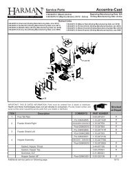
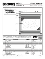
R<strong>5700</strong> ACT Wood StoveACCESSORIESPart DescriptionPart No.Ash Removal System (ARS) 831-1671Blower Assembly 831-1701Door Assembly, Black, with Spring Handles 832-1921Door Assembly, Gold, with Spring Handles 832-1931Door Assembly, Nickel, with Spring Handles DR-57NLNickel Upgrade Kit, (incl 2 hinge pins & 3 UK-DRNLspring handles)Part DescriptionPart No.Queen Anne Legs, Black 831-1240Queen Anne Legs, Gold 831-1250Queen Anne Legs, NickelLEGS-QANLQutside Air Kit, Pedestal or Leg, Floor 831-1780or RearPedestal Assembly 831-1910SERVICE PARTSPart DescriptionPart No.Ash Removal Cast Door Assembly 831-1671Ash Removal Firebox Seal Plate Assy 832-3110Ash Removal Grate 832-2980Baffle, Fiberboard 832-3430Blanket, Ceramic, 1 inch thick, 20-1/8 in. x20-1/8 in832-3401Blower Assembly 831-1701Blower Cord with Speed Control 821-0110Blower Only 812-4900Bracket, Leg Adapter 472-0540Brick Set 832-3410Bricks with Hole (2)SRV436-0380Brick, Single, Uncut 832-0550Brick, Uncut (Set of 6) 832-3040Component Pack (includes owner’s manual, 832-3420EPA card, warranty card, and touch up paint)Component Pack for Black and Gold Doors 831-1931(includes 2 gold spring handles 1/2” and 1/4”and 2 gold hinge pins)Component Pack for Trim Door (includes 2 831-1921gold spring handles 1/2” and 1/4” and 2 goldhinge pins)Part DescriptionPart. No.Door Handle Assembly 472-5130Door, Upgrade Kit to NickelUK-DRNLGasket, (Tape) 3/4 x 5 ft. 832-0460Gasket, (Rope), 34” x 84” 832-1680Glass Assembly 7000-014Handle, Spring, 1/2”, Gold 832-0620Handle, Spring, 1/2”, Nickel 250-8330Handle, Spring, 1/4”, Gold 832-0630Handle, Spring, 1/4”, Nickel 250-8340Hinge Pins, Gold, 1/2” 832-0250Hinge Pins, Nickel, 1/2” 430-5320Manifold Clip/Screws (4) 832-0661Manifold Tube Set (4) 832-3440Outside Air Kit 831-1780Outside Air Rear Channel 436-7020Pedestal Base Assembly 831-1910Speed Control Only (Rheostat) 842-0370Trim Ring, Gold 472-0600Trim Ring, Nickel 472-0690APPLIANCEName Part No. Door Options Base Options<strong>5700</strong> Step Top, Uni-Body, ACT 820-1721 Black , Gold or Nickel Door Queen Anne Legs, Black, Nickel or GoldPedestalSeptember 1, 2008250-7090EPage 25
R<strong>5700</strong> ACT Wood StoveEXPLODED VIEWS4621101211358 97Item Part Name1 Door, Cast2 Door Handle3 Glass, Replacement4 Glass Frame Assembly5 Glass Frame Screws (10)6 Hinge Pins7 Latch, Cam8 Latch Cam key9 Latch, Secondary10 Locking Nut11 Spring Handle, 1/2”12 Trim for Door(Trim Door Assembly only)13 Washer, SpacingFIGURE 26A - DOOR, GLASS AND DOOR HANDLE ASSEMBLYCeramic blanket20-1/8 in.7520-1/8 in.1261011134289Item Part Name1 Air Control Rods2 Ash Removal Grate3 Ash Pan4 Ash Removal Door5 Baffle, Fiberboard6 Blower Assembly7 Ceramic Blanket8 Door Assembly9 Door Handle Assembly10 Leg Mounting Brackets11 Legs, Cast12 Manifold Tubes (4)13 Oak Trim for Pedestal (2)14 Pedestal Base1413FIGURE 26BPage 26250-7090ESeptember 1, 2008
RService And Maintenance Log<strong>5700</strong> ACT Wood StoveDate of Service Performed By Description of ServiceSeptember 1, 2008250-7090EPage 27
R<strong>5700</strong> ACT Wood StoveService And Maintenance Log (Cont’d)Date of Service Performed By Description of ServicePage 28250-7090ESeptember 1, 2008
R<strong>5700</strong> ACT Wood Stove<strong>Home</strong>owner’s NotesSeptember 1, 2008250-7090EPage 29
R<strong>5700</strong> ACT Wood StoveWarranty Policy<strong>Hearth</strong> & <strong>Home</strong> <strong>Technologies</strong> LIMITED WARRANTY<strong>Hearth</strong> & <strong>Home</strong> <strong>Technologies</strong> (“HHT”) and its respective brands extends the following warranty for HHT gas, wood,pellet and electric appliances purchased from an authorized HHT dealer and installed in the United States of America orCanada. Warranty starts with date of purchase by the original owner (End User) except as noted for replacement parts.Warranty PeriodHHT Manufactured Appliances and VentingEPAParts Labor Gas Wood PelletElectricWoodVentingComponents CoveredAll Parts and Material Except1 Year X X X X X Xas covered by Conditions,Exclusion, and LimitationslistedIgniters, Electronic Components,and GlassX X2 yearsX X X X BlowersX Molded Refractory Panels3 years X Firepots5 years 3 years X X Castings & Baffles7 years 3 years X X X10years1 year XFirebox, HHT Chimney, Termination& Heat ExchangerBurners, Logs & RefractoryLimitedLifetime1 year XFirebox & Heat Exchanger90 Days X X X X X X All Replacement PartsSee Conditions, Exclusions, and limitations. 9-01-08CONDITIONS, EXCLUSIONS & LIMITATION OF LIABILITY• This warranty applies to the original owner and is transferable up to two years from date of purchase to the newhomeowner, provided the purchase was made through an authorized dealer or distributor of HHT, and the applianceremains in its original place of installation.• The maximum amount recoverable under this warranty is limited to the purchase price of the product.• In no event shall HHT be liable for any incidental or consequential damages caused by defects in the product.• Adjustments, regular maintenance, cleaning and temporary repairs, or the failure to duplicate the problem in thehome is not covered under this warranty.• This limited warranty does not extend to or include surface finish on the appliance or terminations, door gasketing,glass gasketing, glass discoloration, firebrick, pellet logs, kaowool or other ceramic insulating materials. Rust and/orcorrosion on any of the metal surfaces, cast iron components, baffles, firepots, doors, or firebox area are not coveredby this warranty.• Noise resulting from minor expansion, contraction, or movement of certain parts is normal and complaints related tothis noise are not covered by this warranty.4021-645A 09-01-08Page 30250-7090ESeptember 1, 2008
R<strong>5700</strong> ACT Wood Stove<strong>Hearth</strong> & <strong>Home</strong> <strong>Technologies</strong> LIMITED WARRANTY (Cont’d)• HHT’s obligation under this warranty does not extend to damages resulting from: (1) installation, operation or maintenanceof the appliance not in accordance with the installation instructions; operating instructions and the listingagent identification label furnished with the appliance; (2) installation which does not comply with local building codes;(3) shipping, improper handling, improper operation, abuse, misuse, accident or unworkmanlike repairs; (4) environmentalconditions, inadequate ventilation or drafting caused by tight sealing construction of the structure or handlingdevices such as exhaust fans or forced air furnaces or other such causes; (5) use of fuels other than those specifiedin the operating instructions; (6) installation or use of components not supplied with the appliance or any other componentsnot expressly authorized and approved by HHT; and/or (7) modification of the appliance not expressly authorizedand approved by HHT in writing.• This warranty does not apply to non-HHT venting components, hearth components or other accessories used in conjunctionwith the installation of this product.• This warranty is void if the appliance has been over-fired or operated in atmospheres contaminated by chlorine,fluorine, or other damaging chemicals the appliance is subject to prolonged periods of dampness or condensation, orthere is any damage to the appliance or other components due to water or weather damage which is the result of, butnot limited to, improper chimney or venting installation.• HHT’s liability under this warranty is limited to the replacement and repair of defective components or workmanshipduring the applicable period. HHT may fully discharge all of its obligations under such warranties by repairing thedefective component(s) at HHT’s discretion. Shipping costs are not covered under this warranty.• Some states do not allow exclusions or limitation of incidental or consequential damages, so those limitations may notapply to you. This warranty gives you specific rights; you may also have other rights, which vary from state to state.• EXCEPT TO THE EXTENT PROVIDED BY LAW, HHT MAKES NO EXPRESS WARRANTIES OTHER THAN THEWARRANTY SPECIFIED HEREIN. THE DURATION OF ANY IMPLIED WARRANTY IS LIMITED TO DURATION OFTHE WARRANTY SPECIFIED ABOVE.This Limited Warranty is effective on all HHT appliances sold after September 01, 2008 and supersedes any and all warrantiescurrently in existence.If warranty service is needed, you should contact your installing dealer. If the installing dealer is unable to provide necessaryparts or components, contact the nearest authorized HHT dealer or supplier.4021-645A 09-01-08September 1, 2008250-7090EPage 31
RCONTACT INFORMATION:<strong>Hearth</strong> & <strong>Home</strong> <strong>Technologies</strong>1445 North HighwayColville, WA 99114Division of HNI INDUSTRIESPlease contact your Quadra-Fire dealer with any questions or concerns.For the number of your nearest Quadra-Fire dealer,visit our web site at www.quadrafire.comCAUTION• Do NOT discard this manual.• Important operating and maintenanceinstructions included.• Read, understand and follow these instrucitonsfor safe installation and operation.• Leave this manual with party responsible foruse and operation.Your Records for Model:<strong>5700</strong> ACT Wood StoveDEALERSHIP WHERE PURCHASED:SERIAL NUMBER:DATE PURCHASED:DATE INSTALLED:__________________________________________________________________________________________________________________________________________________________________________DEALER TELEPHONE:__________________This product may be covered by one or more of the following patents: (United States) 4593510, 4686807, 4766876,4793322, 4811534, 5000162, 5016609, 5076254, 5113843, 5191877, 5218953, 5263471, 5328356, 5341794, 5347983,5429495, 5452708, 5542407, 5601073, 5613487, 5647340, 5688568, 5762062, 5775408, 5890485, 5931661, 5941237,5947112, 5996575, 6006743, 6019099, 6048195, 6053165, 6145502, 6170481, 6237588, 6296474, 6374822, 6413079,6439226, 6484712, 6543698, 6550687, 6601579, 6672860, 6688302B2, 6715724B2, 6729551, 6736133, 6748940,6748942, D320652, D445174, D462436; (Canada)1297749, 2195264, 2225408; or other U.S. and foreign patentspending.Page 32 September 1, 2008250-7090E