Owner's Manual - Hearth & Home Technologies
Owner's Manual - Hearth & Home Technologies
Owner's Manual - Hearth & Home Technologies

Create successful ePaper yourself
Turn your PDF publications into a flip-book with our unique Google optimized e-Paper software.
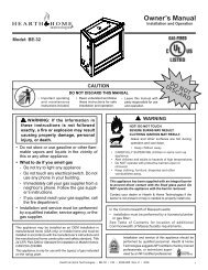
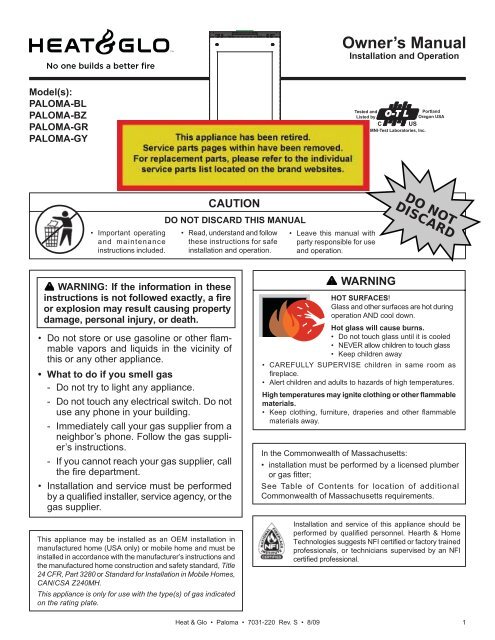
Owner’s <strong>Manual</strong>Installation and OperationModel(s):PALOMA-BLPALOMA-BZPALOMA-GRPALOMA-GYTested andListed byO-T LPortlandOregon USAUSCOMNI-Test Laboratories, Inc.• Important operatingand maintenanceinstructions included.CAUTIONDO NOT DISCARD THIS MANUAL• Read, understand and followthese instructions for safeinstallation and operation.• Leave this manual withparty responsible for useand operation.DO NOTDISCARDWARNING: If the information in theseinstructions is not followed exactly, a fireor explosion may result causing propertydamage, personal injury, or death.• Do not store or use gasoline or other fl ammablevapors and liquids in the vicinity ofthis or any other appliance.• What to do if you smell gas- Do not try to light any appliance.- Do not touch any electrical switch. Do notuse any phone in your building.- Immediately call your gas supplier from aneighbor’s phone. Follow the gas supplier’sinstructions.- If you cannot reach your gas supplier, callthe fi re department.• Installation and service must be performedby a qualified installer, service agency, or thegas supplier.This appliance may be installed as an OEM installation inmanufactured home (USA only) or mobile home and must beinstalled in accordance with the manufacturer’s instructions andthe manufactured home construction and safety standard, Title24 CFR, Part 3280 or Standard for Installation in Mobile <strong>Home</strong>s,CAN/CSA Z240MH.This appliance is only for use with the type(s) of gas indicatedon the rating plate.WARNINGHOT SURFACES!Glass and other surfaces are hot duringoperation AND cool down.Hot glass will cause burns.• Do not touch glass until it is cooled• NEVER allow children to touch glass• Keep children away• CAREFULLY SUPERVISE children in same room asfi replace.• Alert children and adults to hazards of high temperatures.High temperatures may ignite clothing or other flammablematerials.• Keep clothing, furniture, draperies and other fl ammablematerials away.In the Commonwealth of Massachusetts:• installation must be performed by a licensed plumberor gas fi tter;See Table of Contents for location of additionalCommonwealth of Massachusetts requirements.Installation and service of this appliance should beperformed by qualifi ed personnel. <strong>Hearth</strong> & <strong>Home</strong><strong>Technologies</strong> suggests NFI certified or factory trainedprofessionals, or technicians supervised by an NFIcertified professional.Heat & Glo • Paloma • 7031-220 Rev. S • 8/09 1
Read this manual before installing or operating this appliance.Please retain this owner’s manual for future reference.CongratulationsCongratulations on selecting a Heat & Glo gas appliance—an elegant and clean alternative to wood burningappliances. The Heat & Glo gas appliance you haveselected is designed to provide the utmost in safety,reliability, and effi ciency.As the owner of a new appliance, you’ll want to read andcarefully follow all of the instructions contained in thisOwner’s <strong>Manual</strong>. Pay special attention to all Cautions andWarnings.This Owner’s <strong>Manual</strong> should be retained for futurereference. We suggest that you keep it with your otherimportant documents and product manuals.The information contained in this Owner’s <strong>Manual</strong>, unlessnoted otherwise, applies to all models and gas controlsystems.Your new Heat & Glo gas appliance will give you years ofdurable use and trouble-free enjoyment. Welcome to theHeat & Glo family of appliance products!<strong>Home</strong>owner Reference InformationWe recommend that you record the following pertinentinformation about your appliance.Model Name: ___________________________________________ Date purchased/installed: __________________Serial Number: __________________________________________ Location on appliance: ____________________Dealership purchased from: _______________________________ Dealer Phone: __________________________Notes: ____________________________________________________________________________________________________________________________________________________________________________________Listing Label Information/LocationThe model information regarding your specifi c appliance can be found onthe rating plate usually located in the control area of the appliance.Test Lab & Report No.Tested andBeavertonListed byOregon USACOMNI- Test Laboratories, Inc.SERIALNO. 007Serial No.Report No. / Rapport Numero800 West Jefferson Street061-S-63-5Lake City, MN 55041www.heatnglo.comMODEL: PALOMAVENTED GAS APPLIANCENOT FOR USE WITH SOLID FUELFAN TYPE VENTED CIRCULATOR Blower Electrical Rating115 V., 1.5 Amps, 60 Hz, 150 WattsP.4.1-02 Canada Minimum Pipe 69% NG / 71% LPAPPROVED FOR CANADA AND USA TO:ANSI Z21.88b-2003 / CSA 2.33b-2003 Vented Gas Fireplace Heater, and applicable sections of UL307b Gas BurningHeating Appliances for Manufactured <strong>Home</strong>s and Recreational Vehicles, CAN/CG A 2.17-M91 “Gas Fired Appliancesfor use at High Altitudes.”This appliance is manufactured for operation with Natural Gas. For conversion to propane the Manufacturer’s kitprovided with the stove must be used in conjuntion with the instructions in the owner's manual.This vented gas fireplace heater is not for use with air filters.This appliance may be installed in a bedroom or bedsitting room; in Canada remote thermostat installation isrequired.For use with Natural Gas For use with Propane"0-2000’ "0-2000’Input Rate on “HI” (BTU/Hr) 30,000 28,000Input Rate on “LO” (BTU/Hr) 22,500 22,650Main Burner Orifice (DMS) 36 52Minimum Inlet Pressure (Inches W.C.) 4.5” 11”Maximum Inlet Pressure (Inches W.C.) 7.0” 14”Manifold Pressure on “HI” (Inches W.C.) 3.5” 10”Efficiency up to 82.5% 81%AFUE 71% 72.5%This appliance equipped for altitudes 0-2000’ (0-610m) in USA; and in Canada for altitudes of 0-4500’ (0-1370m). In USA forAltitudes above 2000’, the vent configuration, orifice, or combination of both may need to be changed. See Owner’s <strong>Manual</strong> forinformation on making these changes.This appliance must be installed in accordance with local codes, if any (and Commonwealth of Massachusetts approved); ifnone, follow The National Fuel Gas Code,ANSI Z223.1 and NFPA 54; or Canadian Installation Codes CAN/CGA-B149.NOTE: Have the gas supply line installed in accordance with local building codes by a qualified installer approved and/orlicensed as required by the locality. (In the Commonwealth of Massachusetts, installation must be performed by a licensedplumber or gas fitter.)SAMPLEMINIMUM CLEARANCES TO COMBUSTIBLESModel NameManufactured by:DO NOT REMOVE THIS LABELMADE IN U.S.A.Date of Manufacture / Date du Manufacturier2005 2006 2007 Jan Feb Mar Apr May Jun Jul Aug Sep Oct Nov DecManufactured Date2Heat & Glo • Paloma • 7031-220 Rev. S • 8/09
Table of Contents1 Listing and Code ApprovalsA. Appliance Certifi cation . . . . . . . . . . . . . . . . . . . . . . . . . . . . 4B. Glass Specifi cations . . . . . . . . . . . . . . . . . . . . . . . . . . . . . . 4C. BTU Specifi cations . . . . . . . . . . . . . . . . . . . . . . . . . . . . . . . 4D. High Altitude Installations . . . . . . . . . . . . . . . . . . . . . . . . . . 4E. Non-Combustible Materials Specifi cation. . . . . . . . . . . . . . 4F. Combustible Materials Specifi cation . . . . . . . . . . . . . . . . . 4G. Electrical Codes . . . . . . . . . . . . . . . . . . . . . . . . . . . . . . . . . 4H. Requirements for the Commonwealth of Massachusetts . . 52 Getting StartedA. Design and Installation Considerations . . . . . . . . . . . . . . . 6B. Tools and Supplies Needed . . . . . . . . . . . . . . . . . . . . . . . . 6C. Inspect Appliance and Components . . . . . . . . . . . . . . . . . . 63 Framing and ClearancesA. Selecting Appliance Location . . . . . . . . . . . . . . . . . . . . . . . 7B. Clearances to Combustibles . . . . . . . . . . . . . . . . . . . . . . . 7C. Optional Stone Surround Installed . . . . . . . . . . . . . . . . . . . 84 Termination LocationsA. Vent Termination Minimum Clearances . . . . . . . . . . . . . . . 95 Vent InformationA. Venting Components . . . . . . . . . . . . . . . . . . . . . . . . . . . . .11B. Use of Elbows . . . . . . . . . . . . . . . . . . . . . . . . . . . . . . . . . .11C. Measuring Standards . . . . . . . . . . . . . . . . . . . . . . . . . . . . .11D. How to Use the Vent Graph . . . . . . . . . . . . . . . . . . . . . . . 12E. Venting Guidelines . . . . . . . . . . . . . . . . . . . . . . . . . . . . . . 12F. Horizontal Termination . . . . . . . . . . . . . . . . . . . . . . . . . . . 13G. Vertical Termination . . . . . . . . . . . . . . . . . . . . . . . . . . . . . 16H. Cathedral Ceiling . . . . . . . . . . . . . . . . . . . . . . . . . . . . . . . 19I. Class A Metal Chimney . . . . . . . . . . . . . . . . . . . . . . . . . . 20J. Existing Masonry Chimney . . . . . . . . . . . . . . . . . . . . . . . . 21K. Slim Line Wall Thimble . . . . . . . . . . . . . . . . . . . . . . . . . . . 246 Gas InformationA. Fuel Conversions . . . . . . . . . . . . . . . . . . . . . . . . . . . . . . . 26B. Converting to LP Gas . . . . . . . . . . . . . . . . . . . . . . . . . . . . 26C. Gas Pressures . . . . . . . . . . . . . . . . . . . . . . . . . . . . . . . . . 28D. Gas Connection . . . . . . . . . . . . . . . . . . . . . . . . . . . . . . . . 298 Appliance SetupA. Remove Shipping Materials . . . . . . . . . . . . . . . . . . . . . . . 33B. Unbolting Appliance from the Pallet . . . . . . . . . . . . . . . . . 33C. Leveling and Lagging Down the Appliance . . . . . . . . . . . 34D. Accessories . . . . . . . . . . . . . . . . . . . . . . . . . . . . . . . . . . . 34E. Top to Rear Vent Conversion . . . . . . . . . . . . . . . . . . . . . . 35F. Shutter Adjustment . . . . . . . . . . . . . . . . . . . . . . . . . . . . . . 36G. Installing the Vent Restrictor. . . . . . . . . . . . . . . . . . . . . . . 36H. Installing the Baffl e . . . . . . . . . . . . . . . . . . . . . . . . . . . . . . 37I. Positioning the Logs . . . . . . . . . . . . . . . . . . . . . . . . . . . . . 37J. Mineral Wool . . . . . . . . . . . . . . . . . . . . . . . . . . . . . . . . . . 38K. Optional Blower . . . . . . . . . . . . . . . . . . . . . . . . . . . . . . . . 38L. Remote Controls . . . . . . . . . . . . . . . . . . . . . . . . . . . . . . . 42M. Front Door Glass Assembly Installation . . . . . . . . . . . . . . 44N. Inner Glass Door Assembly Replacement . . . . . . . . . . . . 449 Operating InstructionsA. Before Lighting Appliance. . . . . . . . . . . . . . . . . . . . . . . . . 45B. Controls . . . . . . . . . . . . . . . . . . . . . . . . . . . . . . . . . . . . . . 45C. Lighting Appliance . . . . . . . . . . . . . . . . . . . . . . . . . . . . . . 46D. After Appliance is Lit . . . . . . . . . . . . . . . . . . . . . . . . . . . . . 47E. Frequently Asked Questions . . . . . . . . . . . . . . . . . . . . . . 4710 TroubleshootingA. IntelliFire Ignition System . . . . . . . . . . . . . . . . . . . . . . . . . 4811 Maintaining and Servicing ApplianceA. Maintenance Tasks . . . . . . . . . . . . . . . . . . . . . . . . . . . . . . 5112 Reference MaterialsA. Appliance Dimension Diagram Without Stone Surround . 52B. Appliance Dimension Diagram With Stone Surround. . . . 53C. Vent Components Diagram . . . . . . . . . . . . . . . . . . . . . . . 54D. Vent Components List . . . . . . . . . . . . . . . . . . . . . . . . . . . 55E. Service Parts . . . . . . . . . . . . . . . . . . . . . . . . . . . . . . . . . . 56F. Limited Lifetime Warranty . . . . . . . . . . . . . . . . . . . . . . . . . 60G. Contact Information . . . . . . . . . . . . . . . . . . . . . . . . . . . . . 627 Electrical InformationA. Recommendation for Wire . . . . . . . . . . . . . . . . . . . . . . . . 30B. Connecting to the Appliance. . . . . . . . . . . . . . . . . . . . . . . 30C. IntelliFire ® Ignition System Wiring . . . . . . . . . . . . . . . . . . 30D. Loss of Power and Battery Backup Usage . . . . . . . . . . . . 31E. Wall Switch Installation for Fan (Optional) . . . . . . . . . . . . 32 = Contains updated information.Heat & Glo • Paloma • 7031-220 Rev. S • 8/09 3
Note: The following requirements reference variousMassachusetts and national codes not contained in thisdocument.H. Requirements for the Commonwealth ofMassachusettsFor all side wall horizontally vented gas fueled equipmentinstalled in every dwelling, building or structure used inwhole or in part for residential purposes, including thoseowned or operated by the Commonwealth and where theside wall exhaust vent termination is less than seven (7)feet above fi nished grade in the area of the venting, includingbut not limited to decks and porches, the followingrequirements shall be satisfi ed:Installation of Carbon Monoxide DetectorsAt the time of installation of the side wall horizontal ventedgas fueled equipment, the installing plumber or gas fi ttershall observe that a hard wired carbon monoxide detectorwith an alarm and battery back-up is installed on the fl oorlevel where the gas equipment is to be installed. In addition,the installing plumber or gas fi tter shall observe thata battery operated or hard wired carbon monoxide detectorwith an alarm is installed on each additional level ofthe dwelling, building or structure served by the side wallhorizontal vented gas fueled equipment. It shall be theresponsibility of the property owner to secure the servicesof qualifi ed licensed professionals for the installation ofhard wired carbon monoxide detectors.In the event that the side wall horizontally vented gas fueledequipment is installed in a crawl space or an attic,the hard wired carbon monoxide detector with alarm andbattery back-up may be installed on the next adjacentfl oor level.In the event that the requirements of this subdivision cannot be met at the time of completion of installation, theowner shall have a period of thirty (30) days to complywith the above requirements; provided, however, that duringsaid thirty (30) day period, a battery operated carbonmonoxide detector with an alarm shall be installed.Approved Carbon Monoxide DetectorsEach carbon monoxide detector as required in accordancewith the above provisions shall comply with NFPA720 and be ANSI/UL 2034 listed and IAS certifi ed.SignageA metal or plastic identifi cation plate shall be permanentlymounted to the exterior of the building at a minimumheight of eight (8) feet above grade directly in line with theexhaust vent terminal for the horizontally vented gas fueledheating appliance or equipment. The sign shall read,in print size no less than one-half (1/2) inch in size, “GASVENT DIRECTLY BELOW. KEEP CLEAR OF ALL OB-STRUCTIONS”.InspectionThe state or local gas inspector of the side wall horizontallyvented gas fueled equipment shall not approve theinstallation unless, upon inspection, the inspector observescarbon monoxide detectors and signage installedin accordance with the provisions of 248 CMR 5.08(2)(a)1through 4.ExemptionsThe following equipment is exempt from 248 CMR5.08(2)(a)1 through 4:• The equipment listed in Chapter 10 entitled “EquipmentNot Required To Be Vented” in the most currentedition of NFPA 54 as adopted by the Board; and• Product Approved side wall horizontally vented gas fueledequipment installed in a room or structure separatefrom the dwelling, building or structure used inwhole or in part for residential purposes.MANUFACTURER REQUIREMENTSGas Equipment Venting System ProvidedWhen the manufacturer of Product Approved side wallhorizontally vented gas equipment provides a ventingsystem design or venting system components with theequipment, the instructions provided by the manufacturerfor installation of the equipment and the venting systemshall include:• Detailed instructions for the installation of the ventingsystem design or the venting system components; and• A complete parts list for the venting system design orventing system.Gas Equipment Venting System NOT ProvidedWhen the manufacturer of a Product Approved side wallhorizontally vented gas fueled equipment does not providethe parts for venting the fl ue gases, but identifi es“special venting systems”, the following requirementsshall be satisfi ed by the manufacturer:• The referenced “special venting system” instructionsshall be included with the appliance or equipment installationinstructions; and• The “special venting systems” shall be Product Approvedby the Board, and the instructions for that systemshall include a parts list and detailed installationinstructions.A copy of all installation instructions for all Product Approvedside wall horizontally vented gas fueled equipment,all venting instructions, all parts lists for ventinginstructions, and/or all venting design instructions shallremain with the appliance or equipment at the completionof the installation.See Gas Connection section for additional Commonwealthof Massachusetts requirements.Heat & Glo • Paloma • 7031-220 Rev. S • 8/09 5
2GettingStartedA. Design and Installation Considerations C. Inspect Appliance and ComponentsHeat & Glo direct vent gas appliances are designed tooperate with all combustion air siphoned from outside ofthe building and all exhaust gases expelled to the outside.No additional outside air source is required.CAUTIONCheck building codes prior to installation.• Installation MUST comply with local, regional, state andnational codes and regulations.• Consult local building, fire officials or authorities having jurisdictionabout restrictions, installation inspection, and permits.When planning an appliance installation, it’s necessary todetermine the following information before installing:• Where the appliance is to be installed.• The vent system confi guration to be used.• Gas supply piping.• Electrical wiring.• Framing and fi nishing details.• Whether optional accessories—devices such as a fan,wall switch, or remote control—are desired.WARNINGInspect appliance and components for damage.Damaged parts may impair safe operation.• Do NOT install damaged components.• Do NOT install incomplete components.• Do NOT install substitute components.Report damaged parts to dealer.• Carefully remove the appliance and components fromthe packaging.• Remove door and set aside on protective surface. Seepage 44.• Remove log set and component pack from fi rebox.• Report to your dealer any parts damaged in shipment,particularly the condition of the glass.• Read all of the instructions before starting the installation.Follow these instructions carefully during theinstallation to ensure maximum safety and benefit.WARNING<strong>Hearth</strong> & <strong>Home</strong> <strong>Technologies</strong> disclaims anyWARNINGresponsibility for, and the warranty will be voidedby, the following actions:Keep appliance dry.• Installation and use of any damaged appliance or ventsystem component.• Mold or rust may cause odors.• Modifi cation of the appliance or vent system.• Water may damage controls.• Installation other than as instructed by <strong>Hearth</strong> & <strong>Home</strong><strong>Technologies</strong>.B. Tools and Supplies Needed• Improper positioning of the gas logs or the glass door.• Installation and/or use of any component part not approvedBefore beginning the installation be sure that the followingby <strong>Hearth</strong> & <strong>Home</strong> <strong>Technologies</strong>.tools and building supplies are available.Any such action may cause a fire hazard.Reciprocating saw Framing materialPliersHi temp caulking materialHammerGlovesPhillips screwdriver Framing squareFlat blade screwdriver Electric drill and bits (1/4 in.)Plumb lineSafety glassesLevelWrenchesRatchets/Sockets Allen Wrench SetManometerVoltmeterTape measure 1/2 - 3/4 inch length, #6 or #8 Self-drilling screwsOne 1/4 inch female connection (for optional fan)Noncorrosive leak check solution or combustible gas detector6Heat & Glo • Paloma • 7031-220 Rev. S • 8/09
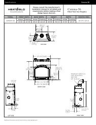
3Framingand ClearancesNote:• Illustrations reflect typical installations and are FORDESIGN PURPOSES ONLY.• Illustrations/diagrams are not drawn to scale.• Actual installation may vary due to individual designpreference.A. Selecting Appliance LocationWhen selecting a location for your appliance it is important toconsider the required clearances to walls (see figure 3.1).WARNINGFire RiskProvide adequate clearance:• Around air openings• To combustibles• For service accessLocate appliance away from traffi c areas.NOTE: For actual appliance dimensions refer to Section12.B. Clearances to CombustiblesFBIKCAEKJC“A” MEASUREMENT IS FROM APPLIANCE TOP, NOT SIDEALCOVEGHAADModel A B C D E F G H I J KPalomaInches 6 10-1/8 12-1/8 54 36 30-3/4 13-1/4 13-1/4 1 15-1/2 5Millimeters 152 257 308 1372 914 781 337 337 25 394 127Figure 3.1Heat & Glo • Paloma • 7031-220 Rev. S • 8/09 7
C. Optional Stone Surround InstalledCEGBFDAAGModel A B C D E F GPaloma SurroundInches 3-1/4 4 30-3/4 36 1 20* 4-3/4Millimeters 83 102 781 914 25 508 121*Distance is measured from fl ue collar to cornerFigure 3.1It is permissible to place the appliance on carpet.CAUTIONSome carpet materials may be sensitive to radiant heatfrom the appliance causing discoloration or odor.Note: Flooring beneath appliance may reach 90 degrees plusroom ambient temperature. Check with flooring manufacturerfor maximum temperature allowed on flooring surfaces.WARNINGFire Risk.• Locate and install appliance to all clearancespecifi cations in manual.WARNINGFire Risk.Odor Risk.Tipping Risk• Install gas stove on a stable, level platform/fl oor strong enough to support gas stovewithout tipping.• USE wood fl ooring, ceramic tile, brick hearthor high pressure laminate fl ooring applieddirectly over the sub-fl ooring material.8Heat & Glo • Paloma • 7031-220 Rev. S • 8/09
4TerminationLocationsA. Vent Termination Minimum ClearancesWARNINGFire Risk.Explosion Risk.Maintain vent clearance to combustibles asspecifi ed.• Do not pack air space with insulation or othermaterials.Failure to keep insulation or other materialsaway from vent pipe may cause fi re.2 FT.MIN.GAS DIRECT VENTTERMINATION CAP20 INCHES MIN.LOWESTDISCHARGEOPENINGX12HORIZONTALOVERHANGVERTICALWALLROOF PITCHIS X/ 12H (MIN.) - MINIMUM HEIGHT FROM ROOFTO LOWEST DISCHARGE OPENINGMeasure vertical clearances from this surface.Measure horizontal clearances from this surface.(See Figure 4.4 for specific clearances)Figure 4.1Roof PitchH (Min.) Ft.Flat to 6/12...........................................................1.0*Over 6/12 to 7/12 .................................................1.25*Over 7/12 to 8/12 .................................................1.5*Over 8/12 to 9/12 .................................................2.0*Over 9/12 to 10/12 ...............................................2.5Over 10/12 to 11/12 .............................................3.25Over 11/12 to 12/12 .............................................4.0Over 12/12 to 14/12 .............................................5.0Over 14/12 to 16/12 .............................................6.0Over 16/12 to 18/12 .............................................7.0Over 18/12 to 20/12 .............................................7.5Over 20/12 to 21/12 .............................................8.0* 3 foot minimum in snow regionsFigure 4.2 Minimum height from roof to lowest dischargeopeningFigure 4.2 specifi es minimum vent heights for variouspitched roofs.AB6in.(minimum)upto20in.18 in. minimum152 mm/508 mm457 mm20 in. and over 0 in. minimumGas, Wood or Fuel OilTermination CapBA*GasTerminationCap *** If using decorative cap cover(s), this distance may need to beincreased. Refer to the installation instructions supplied with thedecorative cap cover.** In a staggered installation with both gas and wood terminations, thewood termination cap must be higher than the gas termination cap.Figure 4.3 Multiple Vertical TerminationHeat & Glo • Paloma • 7031-220 Rev. S • 8/09 9
MNRPQ(See Note 2)VTVSElectricalServiceSVD*VV = VENT TERMINAL X = AIR SUPPLY INLET = AREA WHERE TERMINAL IS NOT PERMITTEDA = 12 inches.................clearances above grade, veranda,(See Note 1) porch, deck or balconyB = 12 inches.................clearances to window or doorthat may be opened, or to permanentlyclosed window. (Glass)D* = 18 inches.................vertical clearance to unventilatedsoffit or to ventilated soffit locatedabove the terminal*30 inches ................for vinyl clad soffi ts and belowelectrical serviceF = 9 inches..................clearance to outside cornerG = 6 inches...................clearance to inside cornerH = 3 ft. (Canada)..........not to be installed above a gasmeter/regulator assembly within 3feet (90 cm) horizontally from thecenter-line of the regulatorI = 3 ft ...........................clearance to gas service regulatorvent outletJ = 9 inches (U.S.A.)12 inches (Canada) clearance to non-mechanicalair supply inlet to building or thecombustion air inlet to any otherapplianceK = 3 ft. (U.S.A.)6 ft. (Canada)...........clearance to a mechanical (powered)air supply inlet** a vent shall not terminate directly above a sidewalk or paved drivewaywhich is located between two single family dwellings and serves bothdwellings.*** only permitted if veranda, porch, deck or balcony is fully open on aminimum of 2 sides beneath the fl oor, or meets Note 2.NOTE 1: On private property where termination is less than 7 feet abovea sidewalk, driveway, deck, porch, veranda or balcony, use of a listed capshield is suggested. (See vents components page)NOTE 2: Termination in an alcove space (spaces open only on one sideand with an overhang) are permitted with the dimensions specified forvinyl or non-vinyl siding and soffi ts. 1. There must be 3 feet minimumbetween termination caps. 2. All mechanical air intakes within 10 feetof a termination cap must be a minimum of 3 feet below the terminationcap. 3. All gravity air intakes within 3 feet of a termination cap must be aminimum of 1 foot below the termination cap.Figure 4.4 Minimum Clearances for TerminationL** = 7 ft. ......................... clearance above paved(See Note 1) sidewalk or a paved drivewaylocated on public propertyM*** = 18 inches................ clearance under veranda, porch,deck, balcony or overhang42 inches ............... vinylS = 6 inches................. clearance from sides of electricalservice(See Note 5)T = 12 inches................ clearance above electrical(See Note 5) serviceNPAlcove Applications= 6 inches ..................non-vinyl sidewalls12 inches ................vinyl sidewalls= 8 ft.Q MINR MAX1 cap 3 feet 2 x Q ACTUAL2 caps 6 feet 1 x Q ACTUAL3 caps 9 feet 2/3 x Q ACTUAL4 caps 12 feet 1/2 x Q ACTUALQ MIN = # termination caps x 3R MAX = (2 / # termination caps) x Q ACTUALNOTE 3: Local codes or regulations may require differentclearances.NOTE 4: Termination caps may be hot. Consider their proximity todoors or other traffi c areas.NOTE 5: Location of the vent termination must not interfere withaccess to the electrical service.WARNING: In the U.S: Vent system termination is NOT permitted inscreened porches. You must follow side wall, overhang and groundclearances as stated in the instructions.In Canada: Vent system termination is NOT permitted in screenedporches. Vent system termination is permitted in porch areas withtwo or more sides open. You must follow all side walls, overhangand ground clearances as stated in the instructions.Heat & Glo assumes no responsibility for the improper performanceof the appliance when the venting system does not meet theserequirements.CAUTION: IF EXTERIOR WALLS ARE FINISHED WITH VINYL SIDING, IT IS SUGGESTED THAT A VINYL PROTECTOR KIT BE INSTALLED.10Heat & Glo • Paloma • 7031-220 Rev. S • 8/09
5VentInformationA. Venting ComponentsIn order to comply with applicable codes and productwarranties, use only following venting components:• <strong>Hearth</strong> & <strong>Home</strong> <strong>Technologies</strong> (HHT)• Simpson Dura-Vent (SDV)DO NOT USE FIELD-FABRICATED VENTING COMPO-NENTS. Refer to the venting manufacturer’s instructions.This product is approved to be vented either horizontally,through the side wall or vertically through the roof. Youmay vent through a Class A or masonry chimney if anapproved adapter is used.This appliance is a direct vent heater. All combustion airmust come directly from the outside of the building. Thevent pipe for this unit consists of an inner and an outerpipe. The inner pipe carries the appliance exhaust out ofthe system, and the outer pipe brings fresh combustionair into the appliance.• A round support box/wall thimble or heat shield isrequired when the venting passes through a combustiblewall.• A support box or ceiling fi restop is required when theventing passes through a ceiling.• Roof fl ashing and a storm collar are required whenventing passes through the roof.• Follow instructions provided with the venting for installationof these items.WARNINGFire Hazard.Explosion Risk.Asphyxiation Risk.Do NOT connect this gas appliance to a chimneyfl ue serving a separate solid-fuel or gas burningappliance.• Vent this appliance directly outside.• Use separate vent system for this appliance.May impair safe operation of this appliance orother appliances connected to the fl ue.B. Use of ElbowsCAUTIONALL vent confi guration specifi cations MUST be followed.• This product is tested and listed to these specifi cations.• Appliance performance will suffer if specifications are notfollowed.Diagonal runs have both vertical and horizontal vent aspectswhen calculating the effects. Use the rise for thevertical aspect and the run for the horizontal aspect (seeFigure 5.1).Two 45º elbows may be used in place of one 90º elbow. On45º runs, one foot of diagonal is equal to 8-1/2 (216 mm)inches horizontal run and 8-1/2 (216 mm) inches verticalrun. A length of straight pipe is allowed between two 45ºelbows (see Figure 5.1).Figure 5.1Vertical12 in.8-1/2 in.Horizontal8-1/2 in.C. Measuring StandardsVertical and horizontal measurements were made usingthe following standards.1. Pipe measurements are from center line to center line.2. Horizontal terminations are measured to the outsidemounting surface (fl ange of termination cap) (seeFigure 4.1) on page 9.3. Vertical terminations are measured to the top of the lastpipe before termination cap.4. Horizontal pipe installed level with no rise.Heat & Glo • Paloma • 7031-220 Rev. S • 8/09 11
D. How to Use the Vent Graph1. Measure the distance from the top of appliance to thecenter of the 90° elbow. On the graph below, draw ahorizontal line from that measurement on the verticalaxis across until it intersects with the slanted line.2. From the point of this intersection, draw a vertical lineto the bottom of the graph.3. The point at which this line meets the bottom line of thegraph is the maximum length of the horizontal run.Example 1: If the vertical dimension from the top of theappliance to the center of the 90° elbow is 7 ft. (2 m), thehorizontal run to the outer wall fl ange must not exceed 13ft. (4 m).Example 2: If the vertical dimension from the top of theappliance is 21 ft. (6.4 m), the horizontal run to the outerwall fl ange must not exceed 9 ft. (3 m).4. Each 90° elbow is equivalent to 3 ft. (914 mm) of ventpipe and each 45° elbow is equivalent to 1 ft. (305mm) of vent pipe, and must be subtracted from ventpipe run. A single vertical to horizontal 90° elbow isalready calculated into the allowable 15 ft. (5 m) run.Each additional 90° elbow reduces the maximumhorizontal distance by 3 ft. (914 mm).Example: The use of three elbows would reduce theallowable horizontal run to 9 ft. (3 - 1 = 2 elbows x 3 ft.= 6 ft.; 15 ft. max. - 6 ft. = 9 ft. max.)E. Venting Guidelines• The maximum horizontal vent run is 15 ft. (5 m) whenthe vertical vent rise is 10 ft. (3 m).• The minimum horizontal vent run is 11-5/8 in. (295mm).• Horizontal sections require a 1/4 in. (6 mm) rise forevery 12 in. (305 mm) of horizontal travel.• Horizontal sections require noncombustible supportevery 3 ft. (914 mm), e.g. wall strap.• Wall thickness: Minimum 4 in. (102 mm). Maximum 20in. (508 mm).• Vent Diameter: Exterior 6-5/8 in. (168 mm); Inner 4 in.(102 mm).EXCEPTION FOR REAR VENT KIT (Snorkel Kit SLK-SNKD), HORIZONTAL INSTALLATION:• The maximum horizontal vent run is 3 ft. (914 mm).• The maximum horizontal vent run with a 45° elbow is 2ft. (610 mm).• No external minimum rise is required. The minimumhorizontal vent run is 11-5/8 in. (295 mm).• For any vertical rise when rear venting, a minimum of 2ft. (610 mm) vertical must be used prior to any horizontalrun.• Snorkel Kit (SLK-SNKD) must be used for horizontalvent runs with no vertical rise.Figure 5.2VERTICAL DISTANCEFROM APPLIANCETO THE 90º ELBOWCLEX. 2EX. 135'34'32'30'28'26'24'22'20'18'16'14'12'10'8'6'4'2'6 ft. (2 m) MinimumVertical TerminationC LFor rear vent or topof appliance for topvent.VENT RESTRICTORPLATE REQUIRED0'11-5/8” 2' 4' 6' 8' 10' 12' 14' 15'(MIN)(MAX)6 in. (152 mm) Minimum starter pipe3 ft. (914 mm) Maximum Horizontal run with novertical pipe and with 1/4 in. (6 mm) rise per foot.TOTAL HORIZONTAL RUN TOOUTSIDE OF EXTERIOR WALL(INCLUDING ELBOWS)To adjust the vent restrictorplate, see page 34.12Heat & Glo • Paloma • 7031-220 Rev. S • 8/09
F. Horizontal TerminationTERMINATION CAP90º ELBOWPIPE LENGTHWALL THIMBLEWALL THIMBLE COVERPIPE LENGTH2. Direct vent pipe is designed with a locking connection.To connect the venting system to the appliance flueoutlet, a twist-lock adapter is built into the applianceat the factory. Wall thickness may vary. Rememberto include wall thickness in minimum clearances whenfiguring venting lengths for your installation needs.3. Female ends of direct vent pipe/elbows are designedto slide straight onto the male ends of adjacent pipesby orienting the pipe indentations so they match andslide into the entry slots on the male ends, see Figure5.4. Push the pipe sections completely together, thentwist-lock one section clockwise approximately onequarterturn, until the two sections are fully locked.The female locking lugs may not be visible from theoutside. They may be located by examining the insideof the female ends.FEMALE LOCKING LUGSMALE LOCKINGCHOOSE BETWEENSLIM LINEWALL THIMBLE ORSTANDARDWALL THIMBLEINTERIOR WALL- 2 IN. (51 MM)CLEARANCE FROMREAR OF STOVECENTER LINEFigure 5.3TRIM RINGSNORKEL CAPMINIMUM OF 6 IN. (152 MM) OFPIPE THROUGH THE WALLSNORKEL CAP KIT (SLK-SNKD) MUST BEUSED FOR HORIZONTAL VENT RUNSWITH NO VERTICAL RISE.1. Determine the desired location of the appliance. Checkto ensure that wall studs or roof rafters are not in theway when the venting system is being planned. If thisis the case, you may want to adjust the location of theappliance.WARNINGFire RiskExhaust Fumes RiskImpaired Performance of Appliance• Ensure vent components are lockedtogether correctly.• Pipe may separate if not properly joined.Figure 5.4WARNINGFire Risk.Explosion Risk.Combustion Fume Risk.Use vent run supports per installationinstructions.Connect vent sections per installationinstructions.• Maintain all clearances to combustibles.• Do NOT allow vent to sag belowconnection point to appliance.• Maintain specifi ed slope (if required).Improper support may allow vent to sag or separate.4. For installations using a round support box/wall thimble(check pipe manufacturer's instructions), mark the wallfor a 10 in. x 10 in. (254 mm x 254 mm) square hole.The center of the square hole should line up with thecenter line of the horizontal pipe, as shown in Figure5.5. Cut and frame the hole in the exterior wall wherethe vent will be terminated. If the wall being penetratedis constructed of noncombustible material, i.e. masonryblock or concrete, a 7 in. (178 mm) diameter hole isacceptable.Heat & Glo • Paloma • 7031-220 Rev. S • 8/09 13
WOODSCREWCENTER OF HOLECENTER LINEWALLTHIMBLECENTER LINEHOTPART HHW2 #841-0670(PREFERRED)WALL THIMBLEFigure 5.6Figure 5.55. Installation requires a minimum of 6 in. (152 mm)horizontal run of vent with a 1/4 in. (6 mm) rise runtowards the termination. Each 1 ft. (305 mm) ofhorizontal venting must include a 1/4 in. (6 mm) rise.Never allow the vent to run downward. This could causehigh temperatures and may present the possibility ofa fire. The location of the horizontal vent terminationon an exterior wall must meet all local and nationalbuilding codes, and must not be easily blocked orobstructed, see Figure 4.4 on page 10.6. For installations requiring a vertical rise on the exteriorof the building, the HHT RHVK snorkel kit (Part #844-8921) is available with a 14 in. (356 mm) and a 36in. (914 mm) tall snorkel termination cap. Follow thesame installation procedures as used for standardhorizontal terminations. If the snorkel termination mustbe installed below grade (i.e. basement application),proper drainage must be provided to prevent waterfrom entering the snorkel termination. Do not backfillaround snorkel termination.7. Position the horizontal termination cap in the center ofthe 10 in. x 10 in. (254 mm x 254 mm) square hole andrun a bead of non-hardening mastic around its outsideedges, so as to make a seal between it and the wall,attach termination cap to the exterior wall with the fourwood screws provided. The arrow on the vent capshould be pointing up (Figure 5.6).8. The four wood screws provided should be replacedwith appropriate fasteners for stucco, brick, concrete,or other types of sidings.9. Termination cap HHW2 (Part #841-0670) is highlyrecommended on a building with vinyl siding, as thevinyl siding standoff is built in. The pilot hole will be2 in. (51 mm) closer to the bottom of the square thanthe top. Using a framing square, draw a 14 in. x 14 in.(356 mm x 356 mm) square around the pilot hole. SeeFigure 5.7.Figure 5.78 in.(203 mm)7 in.(178 mm)7 in.(178 mm)6 in.(152 mm)10. If you are installing termination cap HHW2, the pipewill be off center on flashing). Ensure that properclearances to combustible materials are maintained. Ifyou are using an approved termination cap other thanHHW2 (part #841-0670) on a building with vinyl siding,a vinyl siding standoff should be installed between thetermination cap and the exterior wall (Figure 5.8, onthe next page). Follow manufacturer’s instructions forattaching the vinyl siding standoff to the horizontaltermination cap. The vinyl siding standoff preventsexcessive heat from possibly melting the vinyl sidingmaterial. The vent terminal cap shall not be recessedinto a wall or siding. Remove siding from the areawhere the standoff will be located.14Heat & Glo • Paloma • 7031-220 Rev. S • 8/09
VINYL SIDINGAPPLY SEALANT TOALL FOUR SIDESSCREWSBOLT HORIZONTAL TOPTO VINYL STANDOFFWARNINGFire RiskExhaust Fumes RiskImpaired Performance of Appliance• Ensure vent components are lockedtogether correctly.• Pipe may separate if not properly joined.WALLTHIMBLECOVERWALL THIMBLESCREWSVINYL SIDING STANDOFF WITHSIDING BENEATH REMOVEDWARNINGDo NOT connect a pipe section to a termination capwithout using the telescoping flue section found on thetermination cap.Figure 5.811. Place the wall thimble cover over the pipe assemblyand slide the appliance and vent assembly towardsthe wall, carefully inserting the vent pipe into the venttermination cap assembly. It is important that the ventpipe extend into the vent termination cap a sufficientdistance so as to result in a minimum pipe overlap of1-1/4 in. (32 mm). Secure the connection between thevent pipe and the vent termination cap by attachingthe two sheet metal strips extending from the venttermination cap assembly into the outer wall of thevent pipe. Use the two sheet metal screws providedto connect the strips to the pipe section (Figure 5.9).WARNINGBurn Risk• Local codes may require installation of acap shield to prevent anything or anyonefrom touching the hot cap.1/4 in. (6 mm)FOLD STRAPHERESHEET METALSCREWFigure 5.9WALL THIMBLE COVER/CEILINGFIRESTOP AS REQUIRED BYLOCAL JURISDICTIONSTRAPWALLTHIMBLENote: The attachment from the vent pipe to the venttermination cap must be sealed with silicone. Terminationcaps shall not be recessed into a wall or siding.Heat & Glo • Paloma • 7031-220 Rev. S • 8/09 15
G. Vertical TerminationVERTICAL TERMINATIONCAP USE PART #SLK-991DASTORM COLLARFLASHINGFIRESTOP40 ft. (12 m)MAXIMUMSUPPORT BOXPIPE LENGTHFigure 5.11On vertical terminations use only Part #SLK-991DA or likecomponents. See page 55.Figure 5.101. Check the installation instructions for required 1 in.(25 mm) clearances (air space) to combustibles whenpassing through ceilings, walls, roofs, enclosures,attic rafters, or other nearby combustible surfaces.See page 16, Figure 5.15. Check the instructions formaximum vertical rise of the venting system, and anymaximum horizontal offset limitations. All offsets mustfall within the set parameters of the vent graph (Figure5.2) located on page 12.Note: Maximum vertical rise allowable is 40 ft. (10.7 m),Figure 5.11. Maximum number of 45º elbows permitted for avertical installation is eight, provided their installation doesnot decrease maximum allowable horizontal run (as specifiedby vent graph, on page 12).WARNINGFire Risk.Explosion Risk.Maintain vent clearance to combustibles asspecifi ed.• Do not pack air space with insulation or othermaterials.Failure to keep insulation or other materialsaway from vent pipe may cause fi re.2. Set the gas appliance in its desired location. Dropa plumb bob down from the ceiling to the position ofthe appliance flue exit, and mark the location wherethe vent will penetrate the ceiling. Drill a small holeat this point. Next, drop a plumb bob from the roof tothe hole previously drilled in the ceiling, and mark thespot where the vent will penetrate the roof. Determineif ceiling joists, roof rafters, or other framing willobstruct the venting system. You may wish to relocatethe appliance, or to offset, as shown in Figure 5.12 toavoid cutting load bearing members.Figure 5.12PLUMBER'S TAPECONNECTED TOWALL STRAPWALLSTRAPTWO 45ºELBOWS16Heat & Glo • Paloma • 7031-220 Rev. S • 8/09
3. To install the round support box/wall thimble cover ina flat ceiling, cut a 10 in. (254 mm) square hole in theceiling, centered on the hole drilled in Step 2. Framethe hole as shown in Figure 5.13.CEILING JOISTSSHINGLES OVERLAP ONTOP EDGE OF FLASHINGCAP AND STORMCOLLAR NOT SHOWNFOR CLARITYFRAMINGROUND CEILINGSUPPORT BOX/WALLTHIMBLE COVERFigure 5.14Figure 5.131-1/2 in. (38 mm)LONG WOODSCREWS4. Assemble the desired lengths of pipe and elbowsnecessary to reach from the appliance up throughthe round support box. Ensure that all pipe and elbowconnections are in their fully twist-locked position.Assemble as instructed.5. Cut a hole in the roof centered on the small drill holeplaced in the roof in Step 2. The hole should be ofsufficient size to meet the minimum requirements forclearance to combustibles, as specified. Continueto assemble lengths of pipe and elbows necessaryto reach from the ceiling support box/wall thimble upthrough the roof line. Galvanized pipe and elbows maybe utilized in the attic, as well as above the roofline.The galvanized finish is desirable above the roofline,due to its higher corrosion resistance.• If an offset is necessary in the attic to avoidobstructions, it is important to support the vent pipeevery 3 ft. (914 mm) to avoid excessive stress on theelbows, and possible separation. Wall straps areavailable for this purpose, Figure 5.12, page 16.• Whenever possible, use 45° elbows, instead of 90°elbows. The 45° elbow offers less restriction to theflow of flue gases and intake air.6. Slip the flashing over the pipe section(s) protrudingthrough the roof. Secure the base of the flashing tothe roof with roofing nails. Ensure the roofing materialoverlaps the top edge of the flashing as shown inFigure 5.14. Verify that the chimney is the requiredheight above the roof. See roof pitch table, Figure 4.3,on page 9.7. Continue to assemble pipe sections until the height ofthe vent (before adding the termination cap) meets theminimum code requirements as outlined in the currentCAN/CGA-B149 Installation Codes (in Canada), theNational Fuel Gas Code NFPA 54/ANSI Z223.1 (inUSA), or local codes. Note that for steep roof pitches,the vent height must be increased. See Roof PitchTable (Figure 4.3, on page 9). In high wind conditions,nearby trees adjoining rooflines, steep pitched roofs,and other similar factors can result in poor draft, ordown drafting. In these cases increasing the ventheight or switching to the high wind termination capmay solve this problem.8. Slip the storm collar over the pipe, and push it downto the top of the flashing (Figure 5.15). Use nonhardeningsealant above and below the joint betweenthe storm collar and the pipe.OPTIONAL HIGH WINDTERMINATION CAPSECURE FLASHING WITHNON-HARDENING SEALANT ANDROOFING NAILSFigure 5.15Heat & Glo • Paloma • 7031-220 Rev. S • 8/09 17
9. Twist-lock the vent cap and seal.Note: For multi-story vertical installations, a ceiling firestopis required at the second floor, and any subsequent floors(Figure 5.16). The opening should be framed to 10 in. x 10 in.(254 mm x 254 mm) inside dimensions, in the same manneras shown in Figure 5.13.NAILSCEILING FIRESTOPMINIMUM 1 in.(25 mm)CLEARANCEMINIMUM 1 in.(25 mm)CLEARANCEMINIMUM 1 in. (25 mm)CLEARANCEMINIMUM 1 in.(25 mm)CLEARANCEFigure 5.16WARNINGFire Risk.Explosion Risk.• Any occupied areas above the first floor,including closets and storage spaces, whichthe vertical vent passed through must beenclosed. The enclosure may be framedand sheetrocked with standard constructionmaterials; however, refer to these installationinstructions for the minimum allowableclearance between the outside of the ventpipe and the combustible surfaces of theenclosure. Do not fill any of the required airspace with insulation.18Heat & Glo • Paloma • 7031-220 Rev. S • 8/09
H. Cathedral Ceiling1. Follow installation Steps 1 and 2 under vertical installationsection, page 16.2. Remove shingles or other roof covering as necessaryto cut the rectangular hole for the support box. Cutthe hole 1/8 in. (3 mm) larger than the support boxoutline.3. Lower the support box through the hole in the roofuntil the bottom of the support box protrudes at least 2in. (51 mm) below the ceiling (Figure 5.17). Align thesupport box both vertically and horizontally with a level.Temporarily tack the support box in place through theinside walls and into the roof sheathing.Figure 5.18CUT HOLE 1/8 in. (3 mm)GREATER IN SIZE THANPATTERN OF SUPPORTBOX AS IT IS PROJECTEDONTO ROOF LINELEVELCATHEDRAL CEILINGSUPPORT BOX2 in. (51 mm) MIN. BELOWFINISHED CEILING6. Place the support clamp (provided with the supportbox) inside the support box (at the bottom), and secureto the pipe section. The clamp allows the support boxto support the weight of the pipe sections. Continue toadd pipe sections until you are above the roofline.7. Complete the cathedral ceiling installation by followingthe same procedures outlined in steps 7 through 9 forvertical installations, pages 17-18.8. Install the black trim collar around the outside of thecathedral ceiling support box (Figure 5.19). The twopieces of the trim collar slide over one another to allowfor easy adjustment around the support box. Using thesix screws provided, secure the four corners and theoverlapping sections of the trim collar to the ceiling.You may want to predrill the holes for the overlappedsections for ease of installation.Figure 5.17TRIM COLLAR4. Using tin snips, cut the support box from the top cornersdown to the roofline, and fold the resulting flaps overthe roof sheathing (Figure 5.18). Before nailing it to theroof, run a bead of non-hardening mastic around thetop edges of the support box to make a seal between itand the roof. Clean out any combustible material frominside the support box.5. Assemble the desired lengths of pipe and elbowsnecessary to reach from the appliance up throughthe round support box. Ensure that all pipe and elbowconnections are in their fully twist-locked position.Assemble as instructed.CATHEDRAL CEILINGSUPPORT BOXFigure 5.19SCREWSHeat & Glo • Paloma • 7031-220 Rev. S • 8/09 19
I. Class A Metal ChimneyTERMINATIONCAP PART #SLK-991DATOP ADAPTER4. Pass the flex pipe down through the center of thechimney system, and center the top adapter on the topof the chimney pipe. Drill four 1/8 in. (3 mm) diameterholes through the top adapter, and into the chimneytop. Ensure that you are drilling into the metal on thechimney. Twist lock the high wind termination cap ontothe top adapter (Figures 5.22 and 5.23).FLASHINGEXISTING METALCHIMNEY SYSTEM4 in. (102 mm)FLEX PIPERETRO CONNECTORDIRECT VENTPIPEFigure 5.20Figure 5.22CAUTIONEnsure that existing chimney is functionally sound andclean.• Have inspection done by qualifi ed chimney sweep orprofessional installer BEFORE converting to direct ventappliance.1. Remove existing chimney cap.2. Measure the distance from the top of the chimney tothe bottom of the ceiling support box, add 3 in. (76mm) to this measurement, and cut a section of 4 in.(101 mm) flex pipe to that length (the flex should befully extended).3. Connect the end of the flex pipe section to theunderside of the top adapter, using four sheet metalscrews (Figure 5.21).Figure 5.23DRILL FOUR 1/8 IN. (3 MM)DIAMETER HOLESHIGH WINDTERMINATION CAPSHEET METAL SCREWSFLEX PIPETOP ADAPTERSHEET METAL SCREWS5. Pull the flex pipe down through the ceiling support box,until it protrudes approximately 3 in. (76 mm). Connectthe flex pipe to the retro connector, and attach withsheet metal screws.6. Push the flex pipe back up into the ceiling support box,center the retro connector, and attach it to the supportbox with sheet metal screws.7. The connection between the appliance and the retroconnector may be completed with sections of directvent pipe.Figure 5.2120Heat & Glo • Paloma • 7031-220 Rev. S • 8/09
J. Existing Masonry ChimneyType ACHIMNEY LINERTERMINATION CAP PART#923GKType BCHIMNEY LINER TERMINATIONCAP PART #923GK30 ft. (9 m) OF 3 in. (76 mm)FLEX LINER EXHAUSTSECTION3 IN. (76 MM) FLEX LINERTHIS SECTION OF THECHIMNEY MUST BE SEALEDCO-AXIAL TO CO-LINEARCONNECTOR PART#923GCLCO-AXIAL TO CO-LINEARCONNECTOR PART #923GCLPIPE LENGTH(OPTIONAL)PIPE LENGTH(OPTIONAL)THE CHIMNEY MUST BESEALED FROM THE 4 ft. (1 m)SECTION TO TERMINATIONUSING A SMOKE SHELF OR ADAMPER. THE SEAL SHOULDBE 6 in. (152 mm) BELOW THEEND OF THE 4 ft. (1 m) AIRINTAKE SECTION.SHOWING TWO 30 FT.(9 M) SECTIONS OFFLEX LINER4 ft. (1 m) OF 3 in. (76 mm)FLEX LINER“AIR INTAKE SECTION”Type C - Up & Out InstallationType D - <strong>Hearth</strong> MountTERMINATION CAPPART #SLK-991DACHIMNEY LINERTERMINATION CAPPART #923GKTOP ADAPTERFLASHING30 FT. (9 m) OF 3 IN. (76 mm)FLEX LINEREXHAUST SECTIONRETROCONNECTOR4 in. (102 mm)FLEX LINERTHIS SECTION OFTHE CHIMNEY MUSTBE SEALED90º ELBOWDIRECTVENT PIPEALCOVE CLEARANCE TOCOMBUSTIBLES MUST BEMAINTAINEDCHIMNEY MUST BE SEALEDFROM 4 FT. (1 m) SECTION TOTERMINATION USING A SMOKESHELF OR A DAMPER*.SEAL SHOULD BE 6 IN. (152 mm)BELOW END OF 4 FT. (1 m) AIRINTAKE SECTION.4 FT. (1 m) OF 3 IN. (76 mm)FLEX LINERAIR INTAKE SECTIONCO-AXIAL TO CO-LINEARCONNECTOR PART# 923GCLFigure 5.24*NOTE: In the Commonwealth of Massachusetts, the word damper shallbe replaced with the words flue restrictor.Heat & Glo • Paloma • 7031-220 Rev. S • 8/09 21
CAUTIONCUT AND BEND FLASHINGAS NEEDED TO FIT CHIMNEYEnsure that existing chimney is functionally sound andclean.• Have inspection done by qualifi ed chimney sweep orprofessional installer BEFORE converting to direct ventappliance.1. Before cutting any holes, assemble the desiredsections of direct vent pipe to determine the center ofthe masonry penetration.2. Once the center point of the penetration has beendetermined, cut a 6 in. (152 mm) diameter holein the masonry. If the hole is too large, the retroconnector might not mount properly; if the hole istoo small, the appliance might starve for intake air. Ifthere is a frame wall in front of the masonry wall, cutand frame a 10 in. (254 mm) square opening in thewall (centered around the 6 in. (152 mm) masonryopening). If there is sheet rock only (no studs) infront of the masonry the 10 in. (254 mm) opening isstill needed, but does not need to be framed. If thehole is framed a round support box/wall thimble isrequired. This allows the retro connector to mountdirectly on the masonry and provide the correctclearances to combustibles (Figure 5.25).10 in. x 10 in.(254 mm x 254 mm)FRAMED OPENING IN WALLRETROCONNECTORSTUDWALLMASONRYCHIMNEYFigure 5.26SEALANT-ADHESIVE4. To determine the length of flex needed, measure from3 in. (76 mm) above the top of the flashing down to thelevel of the opening. Add the distance from the centerof the chimney out through the wall. Cut a piece of 4in. (102 mm) flex to this length (extended to its nominallength). Be sure to leave 2-3 in. (51-76 mm) of flexabove the existing chimney to allow for connection tothe termination kit.5. Connect the flex liner to the top adapter using threesheet metal screws (Figure 5.21 page 20).6. Feed the flex liner through the flashing into thechimney. Carefully feed the flex liner down the chimneyto the bottom and out the opening in the masonry wall,forming an angle to line up the flex liner with the ventopening on the appliance.WARNINGFOUR MASONRY BOLTS(NOT INCLUDED)Figure 5.25WALL THIMBLE COVERNOTE: For hearth applications refer to page 20, Figure 5.24for the use of the 923GCL co-axial to co-linear appliance connector.Fire Risk.Explosion Risk.• Do not let the fl ex liner sag below the levelat which it will connect to the applianceor connector. This could allow hot gas tobecome trapped and potentially become afi re hazard. The fl ex liner path should alwaysbe sloped up toward the termination cap.3. Secure the flashing to the top of the masonry chimneyusing a bead of non-hardening sealant-adhesive. If theflashing is larger than the top of the chimney, cut andfold flashing as needed to fit chimney (Figure 5.26).7. If additional lengths of flex liner are needed to spanthe chimney height, use a flex coupler to connect thepieces of flex liner together. Connect the flex to thecoupler by using four sheet metal screws for each side(Figure 5.27, on the next page).22Heat & Glo • Paloma • 7031-220 Rev. S • 8/09
FLEX LINER6 in. (152 mm) DIAMETEROPENING IN MASONRY WALLFLEX COUPLERSHEET METAL SCREWSRETROCONNECTORFigure 5.29THREE MASONRY BOLTS(NOT INCLUDED)Figure 5.278. Secure the top adapter to the flashing. Use three sheetmetal screws through the side of the top adapter intothe flange on the flashing (Figure 5.28). Twist lock thehigh wind termination cap on to the top adapter.10. Slide wall thimble cover over retro connector andsecure with masonry bolts (Figure 5.30). If you havea framed wall in front of the masonry, use woodscrews to mount wall thimble cover to framed wall,over retro connector and 10 in. (254 mm) squareframed opening (Figure 5.25, page 22). If needed,add a section of direct vent pipe to the retro connectorin order to extend through the opening in the wallthimble cover.HIGH WIND TERMINATIONCAP #SLK-991DARETROCONNECTORTOP ADAPTORTHREE SHEETMETAL SCREWSWALLTHIMBLE COVERFOUR MASONRY BOLTS(NOT INCLUDED)Figure 5.28FLASHINGFigure 5.309. Attach the flex to the retro connector. Use three sheetmetal screws to attach the flex liner to the connector(Figure 5.29). Mount the retro connector to themasonry wall using masonry bolts. Redrill larger holeson connector as needed. Be careful to ensure that theconnector is centered in the opening and the mountingholes line up with the masonry wall.11. The connection between the appliance and the retroconnector may be completed with sections of directvent pipe.Heat & Glo • Paloma • 7031-220 Rev. S • 8/09 23
K. Slim Line Wall ThimbleBefore you begin review the venting confi gurations in FiguresA, B and C on the next page.Assembling Slim Line Trim Ring and Heat ShieldFigure 5.33 Attach the heat shield to the trim ring withthe four screws provided. Screws go through the heatshield and into the brackets on the trim ring.Figure 5.31 Lay the trim ring on fl at surface and bend upthe six welded brackets into a 90 degree position. Thebrackets along the outer edge of the ring are for locatingthe ring in the center of the hole.Installing Slim Line Trim Ring and Heat ShieldMeasure from the fl oor to the center of the vent pipe. Cutout a 9-1/2 in. (241 mm) hole in the wall. Hold the trimring/heat shield assembly in place and put a mark on theshield with a black marker where it protrudes through theexterior wall. See Figure A on the next page.Use that mark as a guide to trim off excess heat shieldwith a pair of sheet metal shears.3/4 3/4 3/4Figure 5.32 The heat shield is shipped fl at and must behand bent into a half circle before attaching it to the trimring. Bend the heat shield as shown.CAUTIONSharp Edges• Wear protective gloves and safetyglasses during installation.Figure 5.34 When installing the trim ring/heat shieldassembly make sure the trim ring is centered in the holeand that the shield is above the pipe. There must be aminimum of 3/4 in. (19 mm) minimum clearance maintainedto combustibles from the top of the heat shield.Ensure that framing on the inside of the wall is a minimuminner framing diameter of 10 in. x 10. in. (254 mmx 254 mm).The four trim ring mounting screws provided should bereplaced with appropriate fasteners for stucco, brick, concrete,or other types of sidings.24Heat & Glo • Paloma • 7031-220 Rev. S • 8/09
FIG. A 90 DEGREE ELBOWPLACE MARK WHERE PROTRUDES THROUGHEXTERIOR WALL TO CUT OFF EXCESS90° ELBOWUSE HEAT SHIELD / WALL THIMBLECENTER LINEPIPE LENGTHTRIM RINGPIPE LENGTHHTI VENT HHW2 PART #841-0670(RECOMMENDED FOR OPTIMUM PERFORMANCE)FIG. B 45 DEGREE ELBOWTRIM RING45° ELBOWHEAT SHIELDOVER PIPE5 IN. (127 MM) CLEARANCEFROM APPLIANCE CORNERTO COMBUSTIBLE WALLFIG. C MINIMUM CLEARANCE5 IN. (127 MM) CLEARANCEFROM APPLIANCE CORNERINTERIOR WALL - 2 IN. (51MM) CLEARANCE FROMREAR OF STOVEMINIMUM OF 6 IN. (152 MM)OF PIPE THROUGH THE WALLWALL THIMBLECENTER LINEHEAT SHIELD OVERTOP HALF OF PIPEHTI VENT HHW2 PART#841-0670 (RECOMMENDEDFOR OPTIMUM PERFORMANCE)TRIM RINGSnorkel Cap Kit (SLK-SNKD) must be used for horizontal vent runs with no vertical rise.Figure 5.35Heat & Glo • Paloma • 7031-220 Rev. S • 8/09 25
6Gas InformationA. Fuel ConversionsBefore making gas connections ensure that appliance beinginstalled is compatible with the available gas type.Any natural or propane gas conversions necessary tomeet the appliance and locality needs must be made bya qualifi ed technician using <strong>Hearth</strong> & <strong>Home</strong> <strong>Technologies</strong>specifi ed and approved parts.B. Converting to LP GasWARNINGFire Risk.Explosion Risk.• If the information in these instructions is notfollowed exactly, a fi re, explosion or productionof carbon monoxide may result causingproperty damage, personal injury or loss oflife. The qualifi ed service agency is responsiblefor the proper installation of this kit. Theinstallation is not proper and complete untilall the operation of the converted applianceis checked as specifi ed in the manufacturer'sinstructions supplied with the kit.• This conversion kit shall be installed by aqualifi ed service agency in accordance withthe manufacturer's instructions and all applicablecodes and requirements of the authorityhaving jurisdiction. (In the Commonwealth ofMassachusetts installation must be performedby a licensed plumber or gas fitter.)Any damaged valve components should not be installed.If a valve or regulator has been dropped or appears tohave been modifi ed, the valve or regulator should not beinstalled.Tools required: #2 Phillips head screwdriver; Power drill(a 90° drill is helpful); Tamper-resistant Torx Driver TR20;#2 Phillips bit; 5/32 in. (4 mm) Allen wrench; 3/8 in. (10mm) open end wrench.Coversion component list:• LP Burner orifi ce: #52DMS• Pilot orifi ce• Gas valve regulator• Propane conversion plate• LP labelCAUTIONThe gas supply shall be shut off prior to disconnecting theelectrical power before proceeding with the conversion.PROCEDURE FOR CONVERSION:1. Turn off gas to appliance by closing the inlet linevalve.2. Turn off power to the module and valve.3. Remove the front door assembly, inner glass doorassembly and logs.4. To remove the burner, loosen the front screw on thepilot bracket. Slide the tab on the left side at the backof the burner out from under the pilot bracket, and outof the fi rebox. (Fig. 6.1)TAB ON BACKOF BURNERFigure 6.15. Remove the inlet gas line from valve connection.6. Remove the six hold down screws from the fi reboxbottom plate.7. Disconnect the orange and green wires from the controlvalve and lift the bottom plate and valve assemblyfrom the appliance.8. Remove the orange and white wires from the ignitionmodule which is located on the control panel (seeFigure 7.1 on page 31).9. Using a #20 tamper-proof Torx, remove the regulatorand rubber gasket on face of valve (see Figure 6.2).Discard both the regulator and gasket.10.Install the new regulator along with the new rubbergasket included in the conversion kit (see Figure 6.2).WARNINGFire Risk.Explosion Risk.Gas Leak Risk.• Rubber gasket must be seated properly onvalve face.• Do no install a valve or regulator that hasbeen dropped.26Heat & Glo • Paloma • 7031-220 Rev. S • 8/09
VALVE13. Place the round LP label on the bottom base pan.Place the propane conversion plate adjacent to theexisting rating plate.Figure 6.2RUBBERGASKETREGULATOR11. Using a 3/8 in. (10 mm) nut driver or wrench, removethe NG orifi ce and replace it with the LP orifi ce providedin this kit (see Figure 6.3).Note: The qualifi ed service agency installing this conversionMUST enter the day, month, and year, and sign the propaneconversion plate added to the appliance.14. Reinstall the bottom plate and valve assembly intothe appliance. Reinstall the six hold down screws.15. Reconnect the inlet gas line to the valve assemblyand turn on the gas line valve. Check the incomingline for leaks.16. Reconnect the electrical power supply.17. Reconnect the orange wire to the valve assembly.This will allow for the pilot to turn on with the controlswitch in the "ON" position. Check all pilot line connectionsfor leaks. (See Figure 6.4)18. Use a commercially available, non-corrosive leakcheck solution to test for leaks around the pilot. Besure to rinse off all leak check solution following testing.See Figure 6.4 for leak check points. Extinguishthe pilot.WARNINGShock or burn risk.• Disconnect green wire from gas valve.Failure to disconnect green wire could resultin severe burns.Figure 6.312. Unscrew the pilot tube fi tting on the pilot and replacethe orifi ce spud with the one included in the conversionkit (see Figure 6.4).19. Reinstall the green wire on the valve.20. Before reinstalling the burner, ensure that the shuttersetting is fully open. Reattach pilot to pilot shield toburner (see Figure 6.5). Retighten the screw.REATTACHPILOT SHIELDORIFICE SPUDFigure 6.5PILOT TUBEASSEMBLYFigure 6.4Heat & Glo • Paloma • 7031-220 Rev. S • 8/09 27
21. Place one piece grommet over pilot wires and supplytube. Slide and snap into mating rectangular slot.Make sure it fi ts securely. See Figure 6.6.Figure 6.622. Light the pilot and burner and use a commerciallyavailable, non-corrosive leak check solution to test forleaks. Be sure to rinse off all leak check solution followingtesting and prior to placing the appliance intooperation. Extinguish the pilot and burner.23. Reinstall the logs by following the log placementinstructions.24. Reinstall the inner glass door assembly and the frontdoor assembly.25. Turn on the appliance to check for proper burnerfl ame pattern.26. Verify that the signed and dated conversion plate hasbeen added to the appliance.Verify the performance of the ignition system:1. Verify pilot sparks, pilot lights, pilot stops sparking, andthe main burner turns "ON".2. Turn the appliance "OFF". Verify that both the pilot andburner turn "OFF".3. Repeat Step 1 above.4. With the burner "ON", remove the green wire connectedto the valve. The main burner should shut"OFF".5. Reattach the green wire to the valve, and the mainburner should turn back "ON".6. With the main burner "ON", remove the orange wireconnected to the valve. The pilot and burner should goout, and the pilot will start to spark.7. Turn the appliance "OFF" and reattach the orange wireto the valve.WARNINGFire Risk.Explosion Risk.• Disconnect any electrical cords and turnoff gas supply to unit before proceeding ifconverting fuel on an appliance already fullyinstalled.WARNINGFire Risk.Explosion Risk.• If the information in these instructions isnot followed exactly, a fi re, explosion orproduction of carbon monoxide may resultcausing property damage, personal injury orloss of life.• The qualifi ed service agency is responsiblefor the proper installation of this conversionkit. The installation is not proper and completeuntil the operation of the converted applianceis checked as specifi ed in the manufacturer’sinstructions supplied with the kit.C. Gas PressuresProper input pressures are required for optimum applianceperformance. Gas line sizing requirements need tobe made following NFPA54.WARNINGFire Risk.Explosion Hazard.High pressure will damage valve.• Disconnect gas supply piping BEFOREpressure testing gas line at test pressuresabove 1/2 psig.• Close the manual shutoff valve BEFOREpressure testing gas line at test pressuresequal to or less than 1/2 psig.WARNINGVerify inlet pressures.• High pressure may cause overfi re condition.• Low pressure may cause explosion.• Verify minimum pressures when otherhousehold gas appliances are operating.Install regulator upstream of valve if linepressure is greater than 1/2 psig.Pressure requirements for appliance are shown in thetable below. Minimum pressures must be met when otherhousehold gas appliances are operating.Pressure Natural Gas PropaneMinimum inlet pressureMaximum inlet gas pressureManifold pressure5.0 inchesw.c.7.0 inchesw.c.3.5 inchesw.c.11.0 inchesw.c.14.0 inchesw.c.10.0 inchesw.c.28Heat & Glo • Paloma • 7031-220 Rev. S • 8/09
If the pressure is not suffi cient, ensure:• The piping used is large enough.• The supply regulator is adequately adjusted.• That the total gas load for the residence does notexceed the amount supplied.The supply regulator (the regulator that attaches directlyto the residence inlet or to the propane tank) should supplygas at the suggested input pressure listed above. Contactthe local gas supplier if the regulator is at an improperpressure.D. Gas ConnectionNote: Have the gas supply line installed in accordancewith local building codes, if any. If not, follow ANSI223.1. Installation should be done by a qualifi ed installerapproved and/or licensed as required by the locality. (Inthe Commonwealth of Massachusetts installation must beperformed by a licensed plumber or gas fi tter).Note: A listed (and Commonwealth of Massachusetts approved)1/2 inch (13 mm) T-handle manual shut-off valve andfl exible gas connector are connected to the 1/2 inch (13 mm)control valve inlet.• If substituting for these components, please consultlocal codes for compliance.WARNINGGas Leak Risk• Support control when attaching pipe toprevent bending gas line.WARNINGFire or Explosion Hazard• Gas buildup during line purge may ignite.• Purge should be performed by qualified technician.• Ensure adequate ventilation.• Ensure there are no ignition sources such assparks or open fl ames.• A small amount of air will be in the gas supply lines.When fi rst lighting appliance it will take a short time forair to purge from lines. When purging is complete theappliance will light and operate normally.Air only needs to be purged again if gas valve has beenturned to the OFF position.WARNINGCHECK FOR GAS LEAKSExplosion RiskFire RiskAsphyxiation Risk• Check all fi ttings and connections.• Do not use open fl ame.• After the gas line installation is complete, allconnections must be tightened and checkedfor leaks with a commercially-available,non-corrosive leak check solution. Be sureto rinse off all leak check solution followingtesting.Fittings and connections may have loosenedduring shipping and handling.Note: The gap between supply piping and gas access holemay be caulked with high temperature caulk or stuffed withnon-combustible, unfaced insulation to prevent cold airinfi ltration.Leak test all gas line joints and the gas control valve priorto and after starting the appliance.Before making the gas connection, ensure that theappliance you are installing is designed for the type ofgas being supplied. This information can be found on theratings label under the appliance. If the appliance hasbeen converted to propane (LP), the valve cover shouldhave a label stating that the appliance has been convertedto propane.Connect the gas line at the 3/8 in. (10 mm) pipe connectoron the valve at the back of appliance. We recommendconnecting the appliance with an approved flex gas line.If flex gas lines are not approved in your area, you mustconnect a hard pipe to the gas hookup.You must supply a manual shut-off valve in a visiblelocation within 3 ft. (914 mm) of the appliance.WARNINGFire hazard.Do NOT change the valve settings.• This valve has been preset at the factory.• Changing valve settings may result in fi rehazard or bodily injury.HIGH ALTITUDE INSTALLATIONSOmni-Test Laboratories, Inc. listed gas appliances are testedand approved without requiring changes for elevations from0 to 2000 feet in the U.S.A. and 0 to 4500 feet in Canada.When installing this appliance at an elevation above 2000feet, it may be necessary to decrease the input rating bychanging the existing burner orifi ce to a smaller size. Inputrate should be reduced by 4% for each 1000 feet above a2000 foot elevation in the U.S.A. If the heating value of thegas has been reduced, these rules do not apply. To identifythe proper orifi ce size, check with the local gas utility.If installing this appliance at an elevation above 4500 feet(in Canada), check with local authorities.Heat & Glo • Paloma • 7031-220 Rev. S • 8/09 29
7Electrical InformationA. Recommendation for WireSee Figure 7.1 for recommended maximum lead length(two wire) when using wall thermostat/switch.NOTE: This appliance must be electrically wired and groundedin accordance with local codes or, in the absence of localcodes, with National Electric Code ANSI/NFPA 70-latestedition or the Canadian Electric Code, CSA C221.1.• A 110-120 VAC circuit for this product must be protectedwith ground-fault circuit-interrupter protection, incompliance with the applicable electrical codes, whenit is installed in locations such as in bathrooms or nearsinks.B. Connecting to the ApplianceWARNINGWire 110V to electrical junction box.Do NOT wire 110V to valve.Do NOT wire 110V to wall switch.• Incorrect wiring will damage millivolt valves.• Incorrect wiring will override IPI safety lockoutand may cause explosion.1. This appliance may be used with a wall switch, wallmounted thermostat and / or a remote control2. If using thermostat, use one compatible with a millivoltgas valve system.3. Follow parameters for locating thermostat (see individualthermostat instructions) to ensure proper operationof appliance.4. Use low resistance thermostat wire for wiring fromignition system to the wall switch and thermostat.5. Use the following chart for wire sizing.Figure 7.1Wire SizeMax. Length16 gauge 65 feet18 gauge 40 feet20 gauge 25 feet22 gauge 18 feet6. Keep wire lengths as short as possible by removingany excess wire length.7. Low voltage and 110 VAC voltage cannot be sharedwithin the same wall box.8. Ensure the thermostat is mounted level for accuratereadings.9. The thermostat should be mounted on an inside walland not in direct line with the appliance convection air.10. If the thermostat is located too close to the appliance,you may need to set the temperature settingslightly higher to maintain the desired temperaturein your home.Do not connect this appliance to a thermostat servingany other appliance.Bedroom installation in Canada requires this applianceto be connected to a thermostat.WARNINGShock hazard.• This appliance is equipped with a threepronged (grounding) plug for your protectionagainst shock hazard and should be pluggeddirectly into a properly grounded three prongreceptacle. Do not cut or remove the groundingprong from this plug.C. IntelliFire ® Ignition System WiringThis appliance requires a 110 VAC supply to the appliancejunction box for operation. A wiring diagram is shown inFigure 7.2 on the next page.This appliance is equipped with an IntelliFire ® controlvalve which operates on a 3 volt system.This appliance is supplied with a 3 volt AC transformer,which requires the installation of the supplied junctionbox.This appliance is supplied with a battery pack thatrequires two D cell batteries (not included). Batteriescannot be placed in the battery pack while using the 3volt AC transformer. Conversely, the transformer must beunplugged if the battery pack is used.CAUTIONBattery polarity must be correct or module damage willoccur.30Heat & Glo • Paloma • 7031-220 Rev. S • 8/09
GRNORGBRNBRNBLACKPLUG-IN 3VTRANSFORMERON/OFFWALLSWITCHFLAMESPARKER/SENSORIGNITION MODULE3 VACISINTERMITTENTPILOT IGNITORIGNITIONMODULE(3V)WHTNEUTRALVALVEGROUNDREMOTECONTROLHOTBATTERYPACKREDORGGROUND TOAPPLIANCE CHASSIS*TRANSFORMER3 VACPIGGYBACKON/OFF SWITCHPLUG INFigure 7.2JUNCTION BOXVALVENOTE: Appliance will not operateunless properly grounded.CAUTIONLabel all wires prior to disconnection when servicing controls.Wiring errors can cause improper and dangerous operation.Verify proper operation after servicing.D. Loss of Power and Battery Backup Usage1. Disconnect the power supply.2. Remove the front door assembly and lower accesspanel.3. Place two "D" cell batteries into the battery holder.(Figure 7.3)4. Turn on appliance and verify it is operational.5. Replace lower access panel and front door assembly.Shock hazard.• Replace damaged wire with type 105º C ratedwire.• Wire must have high temperature insulation.Unplug whenusing batteriesWARNINGCAUTIONIf IPI battery back-up is installed:• Do not install batteries if the backup mode may not be usedfor extended time.• Batteries may leak.• Install batteries only when needed for power outage.Figure 7.3BATTERY LOCATIONHeat & Glo • Paloma • 7031-220 Rev. S • 8/09 31
E. Wall Switch Installation for Fan (Optional)If the box is being wired to a wall mounted switch for usewith a fan (See Figure 7.4):• The power supply for the appliance must be brought intoa switch box.• The power can then be supplied from the switch boxto the appliance using a minimum of 14-3 with groundwire.• At the switch box connect the black (hot) wire and red(switch leg) wire to the wall switch as shown.• At the appliance connect the black (hot), white (neutral)and green (ground) wires to the junction box asshown.• Add a 1/4 inch insulated female connector to the red(switch leg) wire, route it through the knockout in the faceof the junction box, and connect to the top fan switchconnector (1/4 inch male) as shown.SWITCHMINIMUM 14-3 AWGWITH GROUNDJUNCTION BOXRedBlackWhiteGreenBlackWhiteGreenRedBlackWhiteGreenPOWERSUPPLY WIRESSWITCH BOXRedFigure 7.4 Junction Box Wired to Wall Switch32Heat & Glo • Paloma • 7031-220 Rev. S • 8/09
8Appliance SetupA. Remove Shipping MaterialsRemove shipping materials from inside or underneath thefi rebox.Do not remove the ignitor shield on the pilot assemblyuntil set up is complete. (Figure 8.1)B. Unbolting Appliance from the PalletThe appliance is bolted and screwed to the pallet for shipping.Use a 1/2 in. socket to remove the bolt in center ofbottom plate. Use a Phillips screwdriver to remove the twoscrews in the front of the bottom plate and the two screwsholding the metal strap across the back of the appliance.Refer to Figure 8.3 for locations.PILOT ASSEMBLYIGNITER SHIELDFigure 8.1Gas line and power cord are shipped inside back panel.To access the gas line and power cord, remove the topplate from the appliance. Remove and retain the twoAllen head screws that hold the back panel in place. Referto Figure 8.6, page 33.Using the black grommet located in the component bag,slide it into the bottom of the back panel and feed the powercord through the grommet, as shown in Figure 8.2.Figure 8.3Figure 8.2Heat & Glo • Paloma • 7031-220 Rev. S • 8/09 33
C. Leveling and Lagging Down the ApplianceLagging the appliance down is REQUIRED.LAGGINGCLEARANCEHOLEWARNINGFire Risk.Odor Risk.Tipping Risk• Install gas stove on a stable, level platform/fl oor strong enough to support gas stovewithout tipping.• USE wood fl ooring, ceramic tile, brick hearthor high pressure laminate fl ooring applieddirectly over the sub-fl ooring material.Figure 8.6Place the lag bolt from the component bag in the centerhole in the bottom plate (lagging clearance hole). Theappliance must be lagged down securely to prevent tippingforward.LevelscrewSecuring holesLag bolt holeLevelscrewFigure 8.4Figure 8.7Using pliers, adjust the counterscrews to level the appliance.D. AccessoriesInstall approved accessories per instructions includedwith accessories. See Service Parts List for appropriateaccessories. Refer to Section 16.WARNINGFigure 8.5After unbolting the appliance from the pallet, insert two1/4 20 x 1/1/2 counterscrews.Using pliers, adjust the counterscrews to level the appliance.Shock or fi re risk.Use ONLY optional accessories approved forthis appliance.• Using non-listed accessories voids warranty.• Using non-listed accessories may result in asafety hazard.• Only <strong>Hearth</strong> & <strong>Home</strong> <strong>Technologies</strong> approvedaccessories may be used safely.34Heat & Glo • Paloma • 7031-220 Rev. S • 8/09
E. Top to Rear Vent ConversionNote: When installing this appliance in a rear vent confi gurationwith no vertical rise, a Snorkel Kit must be used.Kit Contents: Top cover (no hole); Back panel (with hole).Tools Required: Power drill; #2 Phillips bit; 5/32 in. (4 mm)Allen wrench; 5/8 in. (16 mm) open end wrench; high-tempsilicone sealant (optional).1. Remove the front door assembly by lifting it off of thespring-loaded latches on top of the appliance. Removethe inner glass door by disengaging the spring-loadedlatches at the bottom of the appliance and lifting it offof the two spring loaded latches at the top of the appliance.2. Remove the top plate with hole and discard. (Figure 8.8).Figure 8.10INNER EXTENSION COLLARDV ADAPTER6. Remove the four screws from the cover plate on rearof appliance. Retain screws. (see Figure 8.11).Figure 8.83. Remove and retain the Allen head screws that hold thesolid back panel in place. (Figure 8.9) Remove anddiscard the solid back panel.PILOT ASSEMBLYFigure 8.117. Install the outer collar with gasket to the rear of appliancewith screws previously removed. Install the innerextension starter collar. (Figure 8.12).8. Install the new back panel (with hole) to the rear ofappliance. Replace the allen head screws removed inStep 3 to hold the back panel in place. (Figure 8.12).Figure 8.94. Remove the four screws from the DV adapter collar.(Figure 8.10) Set aside DV adapter collar and screws.5. Remove the inner extension starter collar (Shown inFigure 8.10) and set aside.Figure 8.12Heat & Glo • Paloma • 7031-220 Rev. S • 8/09 35
9. Install the cover plate removed from the rear of theappliance to the top of the appliance with the screwspreviously removed. (Figure 8.13).10.Install the new solid top.G. Installing the Vent RestrictorThe vent restrictor plate must be installed before installingthe baffle.On the top of inside firebox for top vent ,on back of fireboxfor rear vent, loosen the three screws out about 1/8 in.Place the vent restrictor plate over the the screws andslide into locking position. Retighten the screws. (SeeFigure 8.15.)Top VentRear VentFigure 8.13F. Shutter AdjustmentThe shutter is located on the underside of the burner, onthe burner neck (see Figure 8.14).Figure 8.15For vertical venting above 6 ft. a vent restrictor is required.After installing the vent restrictor plate, remove the innerrings as needed for proper flame height. (Refer to Figure8.16.)Figure 8.14Figure 8.1636Heat & Glo • Paloma • 7031-220 Rev. S • 8/09
H. Installing the BaffleThe baffle is shipped wrapped, inside the firebox. Installthe baffle with the embedded “T” side up, place it on topof the brackets on the inside of the firebox, ensuring backedge of baffle makes contact with the back of the firebox.Place log #1 into the cradle in the burner. Lean the logback towards right corner of firebox.Figure 8.17I. Positioning the LogsRemove the ignitor shield from the pilot assembly prior toinstalling the logs. (Figure 8.18).Figure 8.19Locate log #2 over the pin in log #1 and into notch in log#1. Lean the log back toward the left corner of the firebox.PILOT ASSEMBLYIGNITER SHIELDFigure 8.18While still breakable, the logs do not become fragile untilafter the appliance is burned and they have cured. Aftercuring, any handling must be done with care as breakagecan easily occur.Note: Logs have been designed to work specifi cally with theburner of this appliance. Exact placement will ensure properoperation of your gas appliance.PINFigure 8.20Heat & Glo • Paloma • 7031-220 Rev. S • 8/09 37
J. Mineral WoolWARNINGExplosion Risk.• Follow ember placement instructions in manual.• Do NOT place embers directly over burner ports.• Replace ember material annually.Improperly placed embers interferes with proper burneroperation.BLOWERCONTROLKNOBApply dime size pieces sparingly along front edge ofburner. Do not completely block ports.GROUNDCLIPCONTROLNUTSPEEDCONTROLTEMP.SENSORSWITCHWINGNUTFigure 8.22Installation precautionsThe GFK-160A Blower kit is tested and safe wheninstalled in accordance with this installation manual. It isyour responsibility to read all instructions before startinginstallation and to follow these instructions carefullyduring installation to assure maximum benefit from, andsafe operation, of the blower.Figure 8.21K. Optional BlowerThe GFK-160A Blower has been designed to circulateroom air through the appliance to enhance heat output.The GFK-160A blower system operates on 120 VAC, 60Hz power. This is available through a receptacle in thefactory installed junction box. The junction box is mountedin the bottom of the appliance behind the access panel. Avariable speed control is provided with the blower systemto provide quiet forced air flow at the desired speeds. Atemperature sensor switch, which automatically turns theblower ON/OFF, is also provided with this kit.Tools Required: Powered screwdriver with Phillips headbit; a fl ashlight is helpful.Compare contents of carton with the actual parts received.If any parts are missing or damaged, contact your dealerbefore starting installation. Do not install a damagedblower kit. See Figure 8.22.This blower is carefully engineered and must be installedonly as specified. If you modify it or any of its components,you may cause a fire hazard and will void the WARRANTY.In addition, such action may void the coverage providedby the owner's home insurance.CAUTIONAll wiring should be done by a qualified electrician and shallbe in compliance with local codes and with the NationalElectric Code ANSI/NFPA NO. 70-current (in the UnitedStates), or with the current CSA C22.1 Canadian ElectricCode (in Canada).WARNINGShock RiskExplosion RiskDo NOT wire 110V to gas control valve.Do NOT wire 110V to wall switch.• Incorrect wiring will damage millivolt valves.• Incorrect wiring will override IPI safety lockoutand may cause explosion.38Heat & Glo • Paloma • 7031-220 Rev. S • 8/09
Disconnect all electrical power. Remove the front doorassembly by lifting off of appliance. Remove the loweraccess door. See Figure 8.23.Locate the machine screw underneath the firebox on theright side. Position the temperature sensor switch/bracketassembly over the machine screw and attach with thewing nut. Finger tighten. See Figure 8.26.Figure 8.23Attach enclosed wires to the temperature sensor switch/bracket assembly. The blue wire attaches to the rear ofthe bracket and one of the black wires from the variablespeed control attaches closest to the prepunched screwhole. See Figure 8.24.Black WiresBlue WiresFigure 8.26Note: The switch/bracket assembly must be installed sothat the sensor switch makes contact with the bottom ofthe fi rebox.Attach rheostat in mating feature of control shield so thatorientation of control knob is downward. See Figure 8.27.Figure 8.24Feed the blue wire and other black wire from the variablespeed control behind the gas valve assembly. Insert thewires into the slots indicated.FAN OUTLETFigure 8.27CLIPVARIABLE SPEED CONTROL& TEMPERATURE SENSORSWITCH WIRES GO HEREFigure 8.25Heat & Glo • Paloma • 7031-220 Rev. S • 8/09 39
Attach the ground clip to the control panel. Attach theground wire extension to the ground clip. Attach the theblower ground wire to the ground wire extension.Recommended operating proceduresIgnite the fire in the appliance with the variable speedcontrol switch in an "ON" position. The fan will automaticallyturn on when the temperature sensor switch closesat approximately 110 degrees Fahrenheit. Heated airshould be delivered at the outlet grille. The fan will continueto operate after the appliance is turned OFF until thesensor switch opens.Various conditions (such as appliance model, type ofappliance installation, outside air temperature vs. insideair temperature) can contribute to the length of the timethe blower remains on after the appliance is turned OFF.The blower can be turned off manually with the speedcontrol switch.Figure 8.28Plug the blower cord into the FAN outlet on the junctionbox. Refer to Figure 8.29, on the next page.Push excess wires neatly towards the rear of the appliance.Slide the blower into the bracket as indicated. Ensurethe blower is pushed back into the bracket to allow thereplacement of the lower access door. The magnet stripslocated on the blower feet are designed to hold the blowerin place. See Figure 8.28.Figure 8.29Reattach the switch bracket with the two screws previouslyremoved.Connect the variable speed control and the temperaturesensor switch to the short lead wires of the junction box byplugging in the male and female connectors. See Figure8.31, on the next page).Plug appliance in. Turn the 110-120 VAC service "ON" atthe circuit breaker and turn the speed control switch to the"ON" position.40Heat & Glo • Paloma • 7031-220 Rev. S • 8/09
VARIABLESPEED SWITCHJUNCTION BOXTEMPERATURESENSOR SWITCHBLUEFigure 8.30 Blower Wiring DiagramWARNINGShock hazard.• Replace damaged wire with type 105º C ratedwire.• Wire must have high temperature insulation.Heat & Glo • Paloma • 7031-220 Rev. S • 8/09 41
L. Remote ControlsTools Required: Powered screwdriver with Phillips headbit; hex wrench; 7/16 in. wrench; manometer.Disconnect electricity at the circuit breaker before beginningthis installation.Familiarize yourself with the instructions enclosed withthe remote control kit.Remote receiverRemove the top plate from the appliance. Remove theAllen head screws attaching the back panel to the appliance.Retain screws.Remove the front glass door assembly and the loweraccess door.Using two wire ties from the appliance component bag,mount the remote receiver to the rear of the controlpanel.Feed the red and orange wires to the front of the appliance.Remove the optional blower, if installed.Plug the 3-prong remote receiver cord into the junctionbox (REM/AUX). Refer to Figure 8.30, on page 41.Plug the 2-prong blower cord directly into the 3-prongpolarized plug on the back of the receiver. This receptacleoutput is 110/120 VAC, 3 AMP.Attach the ground wire from the blower onto the groundingclip.Attach red wires from the remote receiver to the ON/OFFswitch.Reinstall the blower into the blower bracket.Installing flame control solenoidRemove the screw and knob from the variable regulatorand discard. Unscrew the nut from the regulator anddiscard.Remove the bag containing a washer and blue and redplungers from the side of the flame control solenoid.Place washer on flame control solenoid. Insert the correctplunger (blue - Natural Gas, red - LP) into the flamecontrol solenoid.Thread the flame control solenoid with the correct plungerinto the thread hole in the variable regulator. Turn one totwo turns only. DO NOT tighten or damage may occur.See Figure 8.32.GAS CONTROLVALVEWASHERFLAME CONTROLSOLENOIDVARIABLEREGULATORKNOBSCREW3 Prong CordNUTVARIABLEREGULATORWASHERWires TiesFLAMECONTROLSOLENOIDPLUNGERJAM NUTFigure 8.31Figure 8.32 Flame Control Solenoid42Heat & Glo • Paloma • 7031-220 Rev. S • 8/09
ORANGEORANGEREDREDBRNORANGEGREENWHITEORANGEORANGEREDREDWiring the flame control solenoid:Connect the two leads from the flame control solenoid tothe orange leads from the receiver. See Figure 8.33.REMOTE RECEIVERIGNITION MODULE3 VACIINTERMITTENTPILOT IGNITORSREMOTERECEIVERTRANSFORMER3 VACORANGEPLUGINBRNBRNGROUND TOFIREPLACE CHASSISREDBLUEBLACKREDREDREDRED JUMPERWIRE TOBROWNORANGEBATTERY PACKVALVEPIGGYBACKON/OFF SWITCHJAM NUTFLAMECONTROLSOLENOIDPLUNGERORANGEREGULATORTOWERORANGEFigure 8.34 Remote Control IPI Wiring DiagramFigure 8.33 Remote Receiver / Control SolenoidInstall a manometer into the pressure tap. Plug the remotereceiver into the 110-120 VAC power supply.Light the appliance as directed in Section 9 of this manual.Set the manifold pressure on the gas valve by rotating theflame control solenoid. Adjust until the reading on themanometer is 3.5 in. W.C. for natural gas or 10 in. W.C.for LP.Tighten the jam nut to the face of the variable regulatorbody. See Figure 33 Turn the main gas knob on the gasvalve OFF. Remove the manometer from the pressure tapand screw the tap closed.Follow the instructions from the remote control kit tooperate and program the remote control.Heat & Glo • Paloma • 7031-220 Rev. S • 8/09 43
M. Front Door Glass Assembly InstallationRemove the front door assembly by pulling bottom of frontaway from appliance and lifting it off of the spring-loadedlatches on top of the appliance (see Figure 8.35).N. Inner Glass Door Assembly ReplacementTurn the appliance OFF and let it cool down before replacingthe inner glass door assembly.With the front door assembly removed from the appliance,remove the inner glass door assembly by disengaging thespring-loaded latches at the bottom of the appliance andlifting off of the two spring-loaded latches at the top of theappliance.Replace with a new inner glass door assembly.Figure 8.35Position the four fl at 1/4 in. (6 mm) spacer washers on thefront door so that the four mounting screws pass throughthem. Position the glass over the front door.Install the four protective barrels into the glass and thefour nylon washers on top of the glass.From inside the door front, pass the screws through to theoutside and thread on the caps until tight. See Figure 8.36.CAP AND BARREL FASTENER SYSTEMScrewNylon washer on backand front of glassFigure 8.37 Complete AssemblyWARNINGHandle glass doors with care.• Inspect the gasket to ensure it is undamaged.• Inspect the glass for cracks, chips or scratches.• Do NOT strike, slam or scratch glass.• Do NOT operate appliance with glass door removed,cracked, broken or scratched.• Replace glass door assembly as a complete appliance.Finishing CapProtective barrel sleevethrough hole in the glassBack side offront doorFigure 8.3644Heat & Glo • Paloma • 7031-220 Rev. S • 8/09
Optional FutureSwitch Location9OperatingInstructionsA. Before Lighting ApplianceRead this entire manual prior to using the appliance.Failure to follow the instructions may result in propertydamage, bodily injury, or even death.CAUTIONIf installing IntelliFire ignition battery backup:• Do not install batteries if the backup mode may not beused for extended time.• Batteries may leak.• Install batteries only when needed for power outage.Before operating this appliance have a qualified technician:• Remove all shipping materials from inside and/orunderneath the fi rebox.• Review proper placement of logs and mineral wool.• Check the wiring.• Check the baffl e adjustment.• Ensure that there are no gas leaks.• Ensure that the glass is sealed and in the properposition.• Ensure that the fl ow of combustion and ventilation air isnot obstructed (front grilles and vent caps).WARNINGGlass door must be in place whenappliance is operating.Risk of:• Combustion Fumes• FireDo NOT operate appliance with glassdoor removed.• Open viewing glass for servicing only.• Glass door MUST be in place and sealed before operatingappliance.• Only use glass door certifi ed for use with appliance.• Glass replacement should be done by qualifi ed technician.B. ControlsOn/off Switch: When this switch is in the ON position, thepilot ignitor is engaged until temperature is established.The burner automatically turns on.Valve Variable Control: This knob controls the flameheight from low (“LO”) to high (“HI”). The indicator on thevalve indicates the position of the knob.Variable Speed Control: The blower is optional installedon the appliance and this knob controls the speed of theblower that pushes the heated air into the room.Valve Variable ControlWARNINGHOT SURFACES!Glass and other surfaces are hot duringoperation AND cool down.Hot glass will cause burns.• Do not touch glass until it is cooled• NEVER allow children to touch glass• Keep children away• CAREFULLY SUPERVISE children in same room asfi replace.• Alert children and adults to hazards of high temperatures.High temperatures may ignite clothing or otherflammable materials.• Keep clothing, furniture, draperies and other fl ammablematerials away.WARNINGDo NOT use this appliance if any part has been under water.Immediately call a qualifi ed service technician to inspect theappliance and to replace any part of the control system andany gas control which has been under water.Note: If using a remote control wall switch, or thermostat,the On/Off Switch must be left “OFF”. Turning the On/OffSwitch to “ON” will keep the appliance on continually.CONTROL PANELVariable SpeedControl KnobON/OFF SwitchWARNINGImproper installation, adjustment, alteration, service ormaintenance can cause injury or property damage. Refer tothe owner’s information manual provided with this appliance.For assistance or additional information consult a qualifi edinstaller, service agency or the gas supplier.Figure 9.1Heat & Glo • Paloma • 7031-220 Rev. S • 8/09 45
C. Lighting ApplianceIPI IgnitionFOR YOUR SAFETYREAD BEFORE LIGHTINGWARNING: If you do not follow these instructionsexactly, a fi re or explosion may result causing propertydamage, personal injury or loss of life.A. This appliance is equipped withan intermittent pilot ignition (IPI)device which automatically lightsthe burner. Do not try to light theburner by hand.B. BEFORE LIGHTING, smell allaround the appliance area for gas.Be sure to smell next to the fl oorbecause some gas is heavier thanair and will settle on the fl oor.WHAT TO DO IF YOU SMELL GAS• Do not try to light any appliance.• Do not touch any electric switch; donot use any phone in your building.WARNING:DO NOT CONNECT 110 VAC TOTHE CONTROL VALVE.Improper installation, adjustment, alteration,service or maintenance cancause injury or property damage. Referto the owner’s information manualprovided with this appliance.This appliance needs fresh air forsafe operation and must be installedso there are provisions for adequatecombustion and ventilation air.If not installed, operated, and maintainedin accordance with the manufacturer’sinstructions, this productcould expose you to substances in fuelor fuel combustion which are known tothe State of California to cause cancer,birth defects, or other reproductiveharm.Keep burner and control compartmentclean. See installation and operatinginstructions accompanying appliance.• Immediately call your gas supplierfrom a neighbor’s phone. Followthe gas supplier’s instructions.• If you cannot reach your gas supplier,call the fi re department.C. Do not use this appliance if anypart has been under water. Immediatelycall a qualifi ed service technicianto inspect the appliance andto replace any part of the controlsystem and any gas control whichhas been under water.CAUTION:Hot while in operation. Do not touch.Keep children, clothing, furniture, gasolineand other liquids having flammablevapors away.Do not operate the appliance withpanel(s) removed, cracked or broken.Replacement of the panel(s) should bedone by a licensed or qualifi ed serviceperson.NOT FOR USEWITH SOLID FUELFor use with natural gas and propane.A conversion kit, as supplied by themanufacturer, shall be used to convertthis appliance to the alternate fuel.Also Certified for Installation in aBedroom or a Bedsitting Room.For assistance or additional information,consult a qualifi ed installer, serviceagency or the gas supplier.LIGHTINGINSTRUCTIONS(IPI)1. Turn off all electric power to the appliance.2. This appliance is equipped with an ignitiondevice which automatically lights the burner.Do not try to light the burner by hand.GASVALVE3. Wait five (5) minutes to clear out any gas.Then smell for gas, including near the floor. Ifyou smell gas, STOP! Follow “B” in the SafetyInformation located on the left side of this label.If you don’t smell gas, go to next step.4. Turn on all electric power to the appliance.5. To light the burner, fl ip the ON/OFF switch tothe “ON” position. (The ON/OFF switch mayinclude a wall switch if so equipped).6. If the appliance will not operate, follow the instructions“To Turn Off Gas to Appliance” andcall your service technician or gas supplier.TO TURN OFFGAS TO APPLIANCE1. Turn off all electric power to the appliance ifservice is to be performed.2. Flip ON/OFF switch to the “OFF” position.593-913DFor additional information on operating your<strong>Hearth</strong> & <strong>Home</strong> <strong>Technologies</strong> fi replace, please refer to www.fi replaces.com.Final inspection by46Heat & Glo • Paloma • 7031-220 Rev. S • 8/09
D. After Appliance is LitInitial Break-in ProcedureWhen you light the appliance, you may notice that it producesheat which does have an associated odor or smell.If you feel this odor is excessive it may require the initialthree to four hour continuous burn on high followed by asecond burn up to 12 hours to fully drive off any odor frompaint and lubricants used in the manufacturing process.Condensation of the glass is normal.NOTE: The appliance should be run three to four hourson the initial start-up. Turn it off and let it cool completely.Remove and clean the glass. Replace the glass and runthe appliance for an additional 12 hours. This will help tocure the products used in the paint and logs.During this break-in period it is recommended that somewindows in the house be opened for air circulation. This willhelp avoid setting off smoke detectors, and help eliminate anyodors associated with the appliance’s initial burning.WARNINGFire Risk.High Temperatures.Keep combustible household items away fromappliance.Do NOT obstruct combustion and ventilation air.• Do NOT place combustible items on top of orin front of appliance.• Keep furniture, draperies away fromappliance.CAUTION• Prevent accidental appliance operation when notattended.• Unplug or remove batteries from remote control if absentor if appliance will not be used for an extended period oftime.• Property damage possible from elevated temperatures.CAUTIONSmoke and odors released during initial operation.• Open windows for air circulation.• Leave room during initial operation.• Smoke may set off smoke detectors.Smoke and odors may be irritating to sensitiveindividuals.WARNINGFire Hazard.Keep combustible materials, gasoline andother fl ammable vapors and liquids clear ofappliance.• Do NOT store fl ammable materials in theappliance’s vicinity.• Do NOT use gasoline, lantern fuel, kerosene,charcoal lighter fl uid or similar liquids in thisappliance.• Combustible materials may ignite.E. Frequently Asked QuestionsISSUECondensation on the glassBlue flamesOdor from applianceFilm on the glassMetallic noiseIs it normal to see the pilot fl ame burncontinually?SOLUTIONSThis is a result of gas combustion and temperature variations. As the appliance warms, thiscondensation will disappear.This is a result of normal operation and the fl ames will begin to yellow as the appliance is allowedto burn for 20 to 40 minutes.When fi rst operated, this appliance may release an odor for the fi rst several hours.This is caused by the curing of the paint and the burning off of any oils remaining frommanufacturing.This is a normal result of the curing process of the paint and logs. Glass should be cleanedwithin 3 to 4 hours of initial burning to remove deposits left by oils from the manufacturingprocess. A non-abrasive cleaner such as gas fi replace glass cleaner may be necessary. Seeyour dealer.Noise is caused by metal expanding and contracting as it heats up and cools down, similar tothe sound produced by a furnace or heating duct. This noise does not affect the operation orlongevity of the appliance.In an IntelliFire ignition system it is normal to see the pilot fl ame, but it should turn off whenON/OFF is turned off.Heat & Glo • Paloma • 7031-220 Rev. S • 8/09 47
10 TroubleshootingWith proper installation, operation, and maintenance your gas appliance will provide years of trouble-free service. If you doexperience a problem, this troubleshooting guide will assist a qualifi ed service person in the diagnosis of a problem and thecorrective action to be taken. This troubleshooting guide can only be used by a qualifi ed service technician.A. IntelliFire Ignition SystemSymptom Possible Cause Corrective Action1. The ignitor/modulemakes noise, but nospark.a. Incorrect wiring. Verify “S” wire (white) for sensor and “I” wire (orange) for ignitorare connected to correct terminals on module and pilot assembly.Reversed wires at the module may cause system to make sparkingnoise, but spark may not be present at pilot hood.b. Loose connections or electricalshorts in the wiring.Verify no loose connections or electrical shorts in wiring from moduleto pilot assembly. Rod closest to pilot hood should be ignitor.Verify connections underneath pilot assembly are tight; also verifyconnections are not grounding out to metal chassis, pilot burner,pilot enclosure, mesh screen if present, or any other metal object.c. Ignitor gap is too large. Verify gap of igniter to pilot hood. The gap should be approximately.17 inch or 1/8 inch.d. Faulty module. Turn ON/OFF rocker switch or wall switch to OFF position. Removeignitor wire “I” from module. Place ON/OFF Rocker switch or wallswitch in ON position. Hold ground wire about 3/16 inch away from“I” terminal on module. If there is no spark at “I” terminal modulemust be replaced. If there is a spark at “I” terminal, module is fi ne.Inspect pilot assembly for shorted sparker wire or cracked insulatoraround electrode.2. Pilot won’t light,there is no noise orspark.a. Transformer installed correctly. Verify that transformer is installed and plugged into module. Checkvoltage of transformer under load at spade connection on modulewith ON/OFF switch in ON position. Acceptable readings of a goodtransformer are between 3.2 and 2.8 volts AC.b. A shorted or loose connection in wiringconfi guration or wiring harness.Remove and reinstall the wiring harness that plugs into module.Verify there is a tight fi t. Verify pilot assembly wiring to module.Remove and verify continuity of each wire in wiring harness.c. Improper wall switch wiring. Verify that 110/VAC power is “ON” to junction box.d. Module not grounded. Verify black ground wire from module wire harness is grounded tometal chassis of appliance.e. Faulty module. Turn ON/OFF rocker switch or wall switch to OFF position. Removeignitor wire “I” from module. Place ON/OFF Rocker switch or wallswitch in ON position. Hold ground wire about 3/16 inch away from“I” terminal on module. If there is no spark at “I” terminal modulemust be replaced. If there is a spark at “I” terminal, module is fi ne.Inspect pilot assembly for shorted sparker wire or cracked insulatoraround electrode.3. Pilot lights but continuesto spark, andmain burner will not ignite.(If the pilot continuesto spark after thepilot fl ame has been lit,fl ame rectifi cation hasnot occurred.)a. A shorted or loose connection insensor rod.b. Poor fl ame rectifi cation or contaminatedsensor rod.Verify all connections to wiring diagram in manual. Verify connectionsunderneath pilot assembly are tight. Verify connections arenot grounding out to metal chassis, pilot burner, pilot enclosure orscreen if present, or any other metal object.Verify that fl ame is engulfi ng sensor rod. If the pilot assembly doesnot have a ground strap, consider installing one to increase fl amerectifi cation. Verify correct pilot orifi ce is installed and inlet gasspecifi cations. Flame carries rectifi cation current, not the gas. Iffl ame lifts from pilot hood, the circuit is broken. A wrong orifi ce ortoo high an inlet pressure can cause pilot fl ame to lift. The sensorrod may be contaminated. Clean sensor rod with emery cloth.48Heat & Glo • Paloma • 7031-220 Rev. S • 8/09
IntelliFire Ignition System - (continued)Symptom Possible Cause Corrective Action3. (Continued) Pilot lightsbut continues to spark,and main burner will notignite. (If the pilot continuesto spark after the pilotfl ame has been lit, fl amerectifi cation has not occurred.)c. Module is not grounded. Verify that module is securely grounded to metal chassisof appliance. Verify that wire harness is fi rmly connected tomodule.d. Damaged pilot assembly or dirty sensorrod.Verify that ceramic insulator around the sensor rod is notcracked, damaged, or loose. Verify connection from sensorrod to white sensor wire. Clean sensor rod with emery clothto remove any contaminants that may have accumulatedon sensor rod. Verify continuity with a multimeter withohms set at lowest range.e. Faulty module. Turn ON/OFF rocker switch or wall switch to OFF position.Remove ignitor wire “I” from module. Place ON/OFFRocker switch or wall switch in ON position. Hold groundwire about 3/16 inch away from “I” terminal on module. Ifthere is no spark at “I” terminal module must be replaced.If there is a spark at “I” terminal, module is fi ne. Inspectpilot assembly for shorted sparker wire or cracked insulatoraround electrode.4. Pilot sparks, but Pilotwill not light.a. Correct gas supply. Verify that incoming gas line ball valve is “open”. Verify thatinlet pressure reading is within acceptable limits, inlet pressuremust not exceed 14 in. W.C.b. Ignitor gap is too large. Verify that spark gap from ignitor to pilot hood is .17 in. or1/8 in.c. Module is not grounded. Verify module is securely grounded to metal chassis ofappliance.d. Module voltage output / Valve/Pilotsolenoid ohms readings.Verify battery voltage is at least 2.7 volts. Replace batteriesif voltage is below 2.7.Heat & Glo • Paloma • 7031-220 Rev. S • 8/09 49
11Maintaining and Servicing ApplianceAlthough the frequency of appliance servicing and maintenance will depend on use and the type of installation, a qualifi edservice technician should perform an appliance checkup at the beginning of each heating season.WARNINGRisk of injury or property damage.Before servicing:• Turn off gas.• Turn off electricity to appliance.• Disable remote control, if one is present.• Ensure appliance is completely cooled.After servicing:• Replace any screen or barrier that was removed.• Reseal and reinstall any venting removed for servicing.WARNINGAnnual inspection by qualifi ed technician recommended.Check:• Condition of glass, glass assembly and glass seal.• Obstructions of combustion and ventilation air.• Burner ignition and operation.• Burner air shutter adjustment• Gas connections and fi ttings.• Obstructions of termination cap.Clean:• Glass• Air passageways, grilles,control compartment• Burner, burner portsRisk of:• Fire• Delayed ignition or explosion• Exposure to combustion fumes• OdorsCAUTIONHandle glass assembly with care.NOTE: Clean glass after initial 3-4 hours operation.Longer operation without cleaning glass maycause a permanent white film on glass.When cleaning glass door:• Avoid striking, scratching or slamming glass.• Do NOT use abrasive cleaners.• Use a hard water deposit glass cleaner on white fi lm.• Do NOT clean glass when hot.• Turn off appliance after 3-4 hours of operation andALLOW TO COOL.• Remove and clean glass assembly.• Replace glass assembly and operate appliance foradditional 12 hours.Refer to maintenance instructions.WARNINGInspect external vent cap regularly.• Ensure no debris blocks cap.• Combustible materials blocking cap may ignite.• Restricted air fl ow affects burner operation.50Heat & Glo • Paloma • 7031-220 Rev. S • 8/09
A. Maintenance TasksInspectGasket Seal, GlassAssembly and GlassValve Compartmentand Firebox TopLogsFireboxBurner Ignition andOperationVentingRemote controlsMaintenance Tasks1. Inspect for scratches, dents or other damage and repair as necessary.2. Verify no obstructions to airfl ow through the louvers.3. Verify maintenance of proper clearance to combustible household objects.1. Inspect gasket seal and its condition.2. Inspect glass panels for scratches and nicks that can lead to breakage when exposed to heat.3. Confi rm there is no damage to glass or glass frame. Replace as necessary.4. Verify that latches engage properly, clip studs are not stripped, and glass attachment components areintact and operating properly. Replace as necessary.5. Clean glass. Replace glass assembly if severely coated with silicate deposits that cannot be removed.1. Vacuum and wipe out dust, cobwebs, debris or pet hair. Use caution when cleaning these areas. Screwtips that have penetrated the sheet metal are sharp and should be avoided.2. Remove any foreign objects.3. Verify unobstructed air circulation.1. Inspect for broken, damaged, or missing logs. Replace as necessary.2. Verify correct log placement and no fl ame impingement causing sooting. Correct as necessary.1. Inspect for paint condition, warpage, corrosion or perforation. Sand and repaint as necessary.2. Replace appliance if fi rebox has been perforated.1. Verify burner is properly secured and aligned with pilot or igniter.2. Clean off burner top, inspect for plugged ports, corrosion or deterioration. Replace burner if necessary.3. Replace ember materials with new dime-size and shape pieces. Do not block ports or obstruct lighting paths.4. Check for smooth lighting and ignition carryover to all ports. Verify there is no ignition delay.5. Inspect for lifting or other fl ame problems.6. Inspect orifi ce for soot, dirt or corrosion.7. Verify manifold and inlet pressures. Adjust regulator as required.8. Inspect pilot fl ame strength. Clean or replace orifi ce as necessary.9. Inspect thermocouple/thermopile or IPI sensor rod for soot, corrosion and deterioration. Clean with emerycloth or replace as required.10. Verify millivolt output. Replace as necessary.1. Inspect venting for blockage or obstruction such as bird nests, leaves, etc.2. Confi rm that termination cap remains clear and unobstructed by plants, etc.3. Verify that termination cap clearance to subsequent construction (building additions, decks, fences orsheds) has been maintained.4. Inspect for corrosion or separation.5. Verify weather stripping, sealing and fl ashing remains intact.1. Verify operation of remote.2. Replace batteries in remote transmitters and battery-powered receivers.Heat & Glo • Paloma • 7031-220 Rev. S • 8/09 51
12Reference MaterialsA. Appliance Dimension Diagram Without Stone SurroundDimensions are actual appliance dimensions. Use for reference only. For framing dimensions and clearances refer to Section 3.ABCHeight includes 3/8 in (9.53 mm) hearth padDEFGI<strong>Hearth</strong> PadHLocation Inches Millimeter Location Inches MillimeterA 18-7/8 479 F 7-1/8 181B 40-3/4 1035 G 30 762C 40-3/8 1025 H 28-7/8 733D 15-7/8 403 I 33-3/4 857E 3 76Figure 12.1Appliance Dimensions52Heat & Glo • Paloma • 7031-220 Rev. S • 8/09
B. Appliance Dimension Diagram With Stone SurroundABDCEF<strong>Hearth</strong> PadHeight includes 3/8 in (9.53 mm) hearth padGHeight includes 3/8 in (9.53 mm) hearth padLocation Inches Millimeter Location Inches MillimeterA 29-5/8 753 E 16-7/8 428B 24-3/8 620 F 34-5/8 879C 30-1/4 768 G 44-5/16 1126D 3-1/4 83Figure 12.2Appliance Dimensions with Stone SurroundHeat & Glo • Paloma • 7031-220 Rev. S • 8/09 53
C. Vent Components Diagram6-1/2 in.165 mm6-9/16 in.167 mm9-7/16 in.240 mm6 in.152 mm6-9/16 in.167 mm9-1/4 in.235 mm6-5/8 in.168 mmSLP456-5/8 in.168 mm9-3/4 in.248 mmSLP906-5/8 in.168 mm6-5/8 in.168 mm5-1/4 in.133 mm6-5/8 in.168 mm7-1/4 in.184 mm6-5/8 in.168 mm7-1/4 in.184 mm13-1/4 in.337 mm6-9/16 in.167 mmSLP4SLP66-5/8 in.168 mm6-9/16 in.167 mmSLP6ASLP12A6-5/8 in.168 mm6-5/8 in.168 mm49-1/4 in.1251 mm6-5/8 in.168 mm37-1/4 in.946 mm25-1/4 in.641 mm13-1/4 in.337 mm6-9/16 in.167 mmSLP126-9/16 in.167 mm6-9/16 in.167 mm6-9/16 in.167 mmSLP24 SLP36 SLP48Figure 12.3 SLP Series Vent ComponentsNote: Pipes overlap 1-3/8 inches (34.93 mm) at each joint.54Heat & Glo • Paloma • 7031-220 Rev. S • 8/09
D. Vent Components ListCOMPONENTSSLP-WT-BK Ceiling Support / Wall Thimble, BlackSLP-CCS-BK Cathedral Ceiling Support, BlackSLP6-BK 6 inch Pipe Length, BlackSLP4-BK 9 inch Pipe Length, BlackSLP12-BK 12 inch Pipe Length, BlackSLP34-BK 24 inch Pipe Length, BlackSLP36-BK 36 inch Pipe Length, BlackSLP48-BK 48 inch Pipe Length, BlackSLP6A-BK 11 inch - 14-5/8 inch Pipe Length, BlackSLP12A-BK 12 inch - 17 inch Pipe, Adjustable, BlackSLP45-BK 45 degree Elbow, BlackSLP90-BK 90 degree Elbow, BlackSLP4 4 inch PipeSLP6 6 inch PipeSLP12 12 inch PipeSLP24 24 inch PipeSLP36 36 inch PipeSLP48 48 inch PipeSLP45 45 degree ElbowSLP90 90 degree ElbowSLP6A 3-6 in. Adjustable Pipe ExtensionSLP12A 3-12 in. Adjustable Pipe ExtensionSLP-RF6 0/12 - 6/12 Roof FlashingSLP-RF12 7/12 - 12/12 Roof FlashingSL-SCD Storm CollarSLP-FS Ceiling FirestopSLP-WS Wall FirestopSLP-HVS Pipe Support Hanger950 Vinyl Protector Kit - SL PipeDRC-RADIUS Decorative Radius CoverHTI-DV-WT Wall ThimbleRF4-8 Roof FlashingSLP-TRAP2SLP-TVHWTERMINATION KITSTrapezoid Termination KitVertical Termination Cap - High WindSLP-SK-BK Horizontal Termination Kit (includes 904B,930D, SLK-01TRD)SLK-SNKDLINK-STOVEVPK-DVSLP-HHW2Snorkel KitAdapter Kit (includes 30 ft. of 4 inch flex,apapters, wall thimble, masonry& ZC flashing, 991DA cap and hardwarepackageVinyl Siding Protector KitHHW2 Horizontal High Wind Cap(recommended for optimal performance)899-4491 HHW2K Horizontal Kit (one 90 degreeblack wall thimble, 24 inch blackpipe, 11 inch - 14-5/8 inch adjustablevent, HHW2 termination cap)844-8921 RHVK Snorkel Kit (with Dura-Vent parts911B and 940)46DVA-SC46DVA-FS46DVA-WS46DVA-IS46DVA-GK46DVA-GCL46DVA-KMCMISCELLANEOUSStorm CollarCeiling FirestopWall StrapAttic Insulation ShieldChimney Liner Termination KitCo-axial / Co-lineal Appliance ConnectorRetrofit Adj. Chimney Connector RetrofitChimney Connector PlateHeat & Glo • Paloma • 7031-220 Rev. S • 8/09 55
. Limite Lietime nt60Heat & Glo • Paloma • 7031-220 Rev. S • 8/09
Heat & Glo • Paloma • 7031-220 Rev. S • 8/09 61
. Contt InomtionHeat & Glo, a brand of <strong>Hearth</strong> & <strong>Home</strong> <strong>Technologies</strong> Inc.7571 215th Street West, Lakeville, MN 55044www.heatnglo.comPlease contact your Heat & Glo dealer with any questions or concerns.For the location of your nearest Heat & Glo dealer,please visit www.heatnglo.com.NOTES ________________________________________________________________________________________________________________________________________________________________________________________________________________________________________________________________________________________________________________________________________________________________________________________________________________________________________________________________________________________________________________________________________________________________________________________________________________________________________________________________________________________________________________________________________________• Important operatingand maintenanceinstructions included.CAUTIONDO NOT DISCARD TIS MANUAL• Read, understand and followthese instructions for safeinstallation and operation.• Leave this manual withparty responsible for useand operation.This product may be covered by one or more of the following patents: (United States) 4593510, 4686807, 4766876, 4793322, 4811534, 5000162, 5016609,5076254, 5113843, 5191877, 5218953, 5263471, 5328356, 5341794, 5347983, 5429495, 5452708, 5542407, 5601073, 5613487, 5647340, 5688568,5762062, 5775408, 5890485, 5931661, 5941237, 5947112, 5996575, 6006743, 6019099, 6048195, 6053165, 6145502, 6170481, 6237588, 6296474,6374822, 6413079, 6439226, 6484712, 6543698, 6550687, 6601579, 6672860, 6688302B2, 6715724B2, 6729551, 6736133, 6748940, 6748942,6769426, 6774802, 6796302, 6840261, 6848441, 6863064, 6866205, 6869278, 6875012, 6880275, 6908039, 6919884, D320652, D445174, D462436;(Canada) 1297749, 2195264, 2225408, 2313972; (Australia) 780250, 780403, 1418504 or other U.S. and foreign patents pending.Printed in U.S.A. - Copyright 200962Heat & Glo • Paloma • 7031-220 Rev. S • 8/09