Owner's Manual - Hearth & Home Technologies
Owner's Manual - Hearth & Home Technologies
Owner's Manual - Hearth & Home Technologies

You also want an ePaper? Increase the reach of your titles
YUMPU automatically turns print PDFs into web optimized ePapers that Google loves.
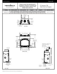
ORANGEORANGEREDREDBRNORANGEGREENWHITEORANGEORANGEREDREDWiring the flame control solenoid:Connect the two leads from the flame control solenoid tothe orange leads from the receiver. See Figure 8.33.REMOTE RECEIVERIGNITION MODULE3 VACIINTERMITTENTPILOT IGNITORSREMOTERECEIVERTRANSFORMER3 VACORANGEPLUGINBRNBRNGROUND TOFIREPLACE CHASSISREDBLUEBLACKREDREDREDRED JUMPERWIRE TOBROWNORANGEBATTERY PACKVALVEPIGGYBACKON/OFF SWITCHJAM NUTFLAMECONTROLSOLENOIDPLUNGERORANGEREGULATORTOWERORANGEFigure 8.34 Remote Control IPI Wiring DiagramFigure 8.33 Remote Receiver / Control SolenoidInstall a manometer into the pressure tap. Plug the remotereceiver into the 110-120 VAC power supply.Light the appliance as directed in Section 9 of this manual.Set the manifold pressure on the gas valve by rotating theflame control solenoid. Adjust until the reading on themanometer is 3.5 in. W.C. for natural gas or 10 in. W.C.for LP.Tighten the jam nut to the face of the variable regulatorbody. See Figure 33 Turn the main gas knob on the gasvalve OFF. Remove the manometer from the pressure tapand screw the tap closed.Follow the instructions from the remote control kit tooperate and program the remote control.Heat & Glo • Paloma • 7031-220 Rev. S • 8/09 43