CASTILE-B PELLET STOVE Owner's Manual Models:
CASTILE-B PELLET STOVE Owner's Manual Models:
CASTILE-B PELLET STOVE Owner's Manual Models:

You also want an ePaper? Increase the reach of your titles
YUMPU automatically turns print PDFs into web optimized ePapers that Google loves.
RRCastile-B FS Pellet Stove1Listing and Code ApprovalsA. Appliance Certification E. BTU & Efficiency SpecificationsModel:Laboratory:Report No.Type:Standard:Castile Pellet StoveOMNI Test Laboratories, Inc.061-S-77d-6.2Solid Fuel Room Heater/Pellet Fuel BurningTypeASTM E1509-04, ULC S627-00 and ULC/ORD-C1482-M1990 Room Heater PelletFuel Burning type and (UM) 84-HUD,Mobile Home Approved.B. Mobile Home ApprovedThis appliance is approved for mobile home installationswhen not installed in a sleeping room and when an outsidecombustion air inlet is used.The structural integrity of the mobile home floor, ceiling, andwalls must be maintained.The appliance must be properly grounded to the frame ofthe mobile home and use only Listed pellet vent Class “L”or “PL” connector pipe.A Quadra-Fire Outside Air Kit must be installed in a mobilehome installation. You must order the Outside Air Kit separately.Note: The appliance is also approved for installationinto a shop.C. Glass SpecificationsThis appliance is equipped with 5mm ceramic glass.Replace glass only with 5mm ceramic glass. Please contactyour dealer for replacement glass.D. Electrical Rating115 VAC, 60 Hz, Start 4.1 Amps, Run 1.1 AmpsNOTE: Some generator or battery back-up systemsmay not be compatable with the micro-processor electronicson this appliance. Please consult the powersupply manufacturer for compatable systems.Particulate EmissionsRating:*BTU Output:Heating Capacity:Hopper Capacity:Fuel:Shipping Weight:0.7 grams/hr8,000 - 30,000 / hrup to 1,500 sq. ft. dependingon climate zone40 lbs +/-5 lbsWood Pellets or Shelled Corn258 lbs*BTU output will vary, depending on the brand of fuel youuse in your appliance. Consult your Quadra-Fire dealerfor best results.WARNING! Risk of Fire! Hearth & Home Technologies disclaimsany responsibility for, and the warranty and agencylisting will be voided by the above actions.DO NOT:• Install or operate damaged appliance• Modify appliance• Install other than as instructed by Hearth & HomeTechnologies• Operate the appliance without fully assembling allcomponents• Overfire• Install any component not approved by Hearth &Home Technologies• Install parts or components not Listed or approved.Improper installation, adjustment, alteration, service ormaintenance can cause injury or property damage.For assistance or additional information, consult a qualifiedinstaller, service agency or your dealer.NOTE: Hearth & Home Technologies, manufacturer ofthis appliance, reserves the right to alter its products,their specifications and/or price without notice.Castile-B FS Pellet Stove2Getting StartedA. Design, Installation & Location Considerations1. Appliance LocationNotice: Check building codes prior to installation.• Installation MUST comply with local, regional, state andnational codes and regulations.• Consult insurance carrier, local building inspector, fireofficials or authorities having jurisdiction over restrictions,installation inspection and permits.It is a good idea to plan your installation on paper, usingexact measurements for clearances and floor protection,before actually beginning the installationConsideration must be given to:• Safety, convenience, traffic flow• Placement of the chimney and chimney connector.• If you are not using an existing chimney, place the appliancewhere there will be a clear passage for a factorybuiltlisted chimney through the ceiling and roof.• Installing an optional outside air kit would affect the locationof the vent termination.Location NOT recommended:• Not the highest point of the roof• Wind loading possibleWindwardRecommended Location:• Above peakMarginal Location:• Below peakRecommended:• Insulated exterior chasein cooler climatesRecommended Location:• Above peak• Inside heated spaceSince pellet exhaust can contain ash, soot or sparks, youmust consider the location of:• Windows• Air Intakes• Air Conditioner• Overhang, soffits, porch roofs, adjacent walls• Landscaping, vegetationWhen locating vent and venting termination, vent above roofline when possible.Warning! Risk of Fire Damaged parts could impair safeoperation. Do NOT install damaged, incomplete or substitutecomponents.CAUTION! If burning shelled field corn, you must use approvedventing specifically designed for corn to prevent corrosionor degradation. Follow the instructions from the ventingmanufacturer.Notice: Locating the appliance in a location ofconsiderable air movement can cause intermittent smokespillage from appliance. Do not locate appliance near:• Frequently open doors• Central heat outlets or returnsMarginal Location:• Wind loading possibleLocation NOT recommended:• Too close to tree• Below adjacent structure• Lower roof line• Avoid outside wallLeewardNOTE: This installation must conform with local codes.In the absence of local codes you must comply with theASTM E1509-95, ULC S627-00 ULC/ORD-C-1482-M1990 (UM) 84-HUDQuadra-Fire is a registered trademarkof Hearth & Home Technologies.Figure 5.1Recommended:Outside Air Intakeon windward sideMulti-level RoofsNOT recommended:Outside Air Intakeon leeward sidePage 4 7021-130D January 21, 2013January 21, 2013 7021-130D Page 5
RRCastile-B FS Pellet StoveCastile-B FS Pellet StoveB. Locating Your Appliance & ChimneyE. Negative PressureWarning! Risk of Asphyxiation! Negative pressure cancause spillage of combustion fumes and soot.F. Fire SafetyG. Tools And Supplies NeededLocation of the appliance and chimney will affectperformance.• Install through the warm airspace enclosed by the buildingenvelope. This helps to produce more draft, especiallyduring lighting and die-down of the fire.• Penetrate the highest part of the roof. This minimizes theeffects of wind loading.• Locate termination cap away from trees, adjacentstructures, uneven roof lines and other obstructions.• Minimize the use of chimney offsets.• Consider the appliance location relative to floor and ceilingand attic joists.• Take into consideration the termination requirements onPage 11.Negative pressure results from the imbalance of air availablefor the appliance to operate properly. It can be strongestin lower levels of the house.Causes include:• Exhaust fans (kitchen, bath, etc.)• Range hoods• Combustion air requirements for furnaces, water heatersand other combustion appliances• Clothes dryers• Location of return-air vents to furnace or air conditioning• Imbalances of the HVAC air handling system• Upper level air leaks such as:- Recessed lighting- Attic hatch- Duct leaksTo minimize the effects of negative air pressure:• Install the outside air kit with the intake facing prevailingwinds during the heating season• Ensure adequate outdoor air for all combustion appliancesand exhaust equipment• Ensure furnace and air conditioning return vents are notlocated in the immediate vicinity of the appliance• Avoid installing the appliance near doors, walkways orsmall isolated spaces• Recessed lighting should be a “sealed can” design• Attic hatches weather stripped or sealed• Attic mounted duct work and air handler joints and seamstaped or sealedTo provide reasonable fire safety, the following should begiven serious consideration:• Install at least one smoke detector on each floor of yourhome.• Locate smoke detector away from the heating applianceand close to the sleeping areas.• Follow the smoke detector manufacturer’s placement andinstallation instructions and maintain regularly.• Conveniently locate a Class A fire extinguisher to contendwith small fires.• In the event of a hopper fire:• Evacute the house immediately.• Notify fire department.Tools and building supplies normally requiredfor installation, unless installing into an existingmasonry fireplace:Reciprocating SawChannel LocksHammerPhillips ScrewdriverTape MeausrePlumb LineLevelFraming MaterialHi-temp Caulking MaterialGlovesSafety GlassesFraming SquareElectric Drill & Bits (1/4”)1/4” Self-Tapping ScrewsMay also need:Vent Support StrapsVenting PaintCAUTION• Do NOT connect this unit to a chimney flueservicing another appliance.• Do NOT connect to any air distributon ductor system.C. Thermostat LocationThe thermostat’s location will have some effect on theappliance’s operation. When the thermostat is located closeto the appliance, it may require a slightly higher temperaturesetting to keep the rest of the house comfortable. If thethermostat location is in an adjacent room or on a differentfloor level, you will notice higher temperatures near theappliance.D. DraftDraft is the pressure difference needed to vent appliancessuccessfully. When an appliance is drafting successfully, allcombustion byproducts are exiting the home through thechimney.Considerations for successful draft include:• Preventing negative pressure• Location of appliance and chimneyNotice: Hearth & Home Technologies assumes noresponsibility for the improper performance of the chimneysystem caused by:• Inadequate draft due to environmental conditions• Downdrafts• Tight sealing construction of the structure• Mechanical exhausting devicesFire Hazard.WARNING• Do not operate appliance before readingand understanding operating instructions.• Failure to operate appliance properly maycause a house fire.WARNINGInspect appliance and components fordamage. Damaged parts may impair safeoperation.• Do NOT install damaged components.• Do NOT install incomplete components.• Do NOT install substitute components.Report damaged parts to dealer.WARNINGFire Risk.Hearth & Home Technologies disclaims anyresponsibility for, and the warranty will bevoided by, the following actions:• Installation and use of any damaged appliance.• Modification of the appliance.• Installation other than as instructed by Hearth & HomeTechnologies.• Installation and/or use of any component part not approvedby Hearth & Home Technologies.• Operating appliance without fully assembling allcomponents.• Operating appliance without legs attached (if supplied withunit).• Do NOT OverfireOr any such action that may cause a fire hazard.H. Inspect Appliance & Components andPre-Use Check List1. Place the appliance in a location near thefinal installation area and follow the proceduresbelow:2. Open the appliance and remove all the partsand articles packed inside the ComponentPack. Inspect all the parts and glass for shippingdamage. Contact your dealer if any irregularitiesare noticed.3. All safety warnings have been read and followed.4. This Owner’s <strong>Manual</strong> has been read.5. Floor protection requirements have been met.6. Venting is properly installed.7. The proper clearances from the appliance andchimney to combustible materials have beenmet.8. The masonry chimney is inspected by a professionaland is clean, or the factory built metalchimney is installed according to the manufacturer’sinstructions and clearances.9. The chimney meets the required minimumheight.10. All labels have been removed from the glassdoor.11. Plated surfaces have been wiped clean, ifapplicable.12. Thermostat or remote has been installed.13. A power outlet is available nearby.Page 6 7021-130D January 21, 2013January 21, 2013 7021-130D Page 7
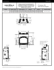
RRCastile-B FS Pellet StoveCastile-B FS Pellet Stove3Dimensions and ClearancesA. Appliance Dimensions24 in. (609mm)12 in.(305mm)B. Clearances to Combustibles (UL and ULC)ABCCAlcove Installation Inches MillimetersMinimum Alcove Height 43 1092Minimum Alcove Side Wall 6 152Minimum Alcove Width 38 965Maximum Alcove Depth 36 914IJ24-5/8 in.(626mm)28-9/16 in.(725mm)Straight Back Against Inches MillimetersWallA Back Wall to Appliance 2 51B Side Wall to Appliance 6 152C LCorner Installation Inches MillimetersFigure 7.1 - Top View22-7/8 in.(582mm)24 in. (609mm)Figure 7.2- Front View27-7/8 in.(708mm)3 in.(76mm)5 in.(126mm)C Walls to Appliance 2 51FInstallations with:3 to 3 inch Top Vent Adapter and3 to 6 inch Offset Adapter KitDGHHDimension to Corner Inches MillimetersI Flue Center Line 10-3/8 264J Back of Top Vent Adapter 9-1/8 232WARNINGFire Risk.Comply with all minimum clearances tocombustibles as specified.EFailure to comply may cause house fire.G17 in.(431mm)28-3/4 in.(730mm)Vertical Installation Inches MillimetersD Back Wall to Flue Pipe 3 76E Side Wall to Cast Top 6 152F Back Wall to Appliance 7 178NOTE:• Illustrations reflect typical installations and are FORDESIGN PURPOSES ONLY.• Illustrations/diagrams are not drawn to scale.• Actual installation may vary due to individual designpreference.Corner Installation Inches Millimeters15-15/16 in.(405mm)16-5/16 in.(414mm)G Walls to Appliance 2 51H Side Wall to Flue Pipe 3 76Figure 7.3 -Side ViewFigure 7.4 - Side View with Top Vent AdapterPage 8 7021-130D January 21, 2013January 21, 2013 7021-130D Page 9
RRCastile-B FS Pellet StoveCastile-B FS Pellet StoveC. Hearth Pad Requirements (UL and ULC)Use a non-combustible floor protector, extending beneathappliance and to the front, sides and rear as indicated.Measure front distance “M” from the surface of the glassdoor.KFigure 10.1ML*USA InstallationsKMust extend 2 inches (51mm) beyond eachside of pipe (shaded area)Figure 10.24Vent InformationA. Chimney and Exhaust Connection1. Chimney & Connector: Use 3 or 4 inch (76-102mm)diameter type "L" or "PL" venting system. It can be ventedvertically or horizontally.2. Mobile Home: Approved for all Listed pellet vent. If usingthe 3 inch (76mm) vertical Top Vent Adapter Kit or the 3to 6 inch (76-152mm) Top Vent Offset Adapter, use Listeddouble wall flue connector. A Quadra-Fire Outside Air Kitmust be used with manufactured home installations.3. Residential: The 3 inch (76mm) vertical Top Vent AdapterKit and the 3 to 6 inch (76-152mm) Top Vent Offset Adapterare tested to use 24 gauge single wall flue connector orListed double wall flue connector to Class A Listed metalchimneys, or masonry chimneys meeting InternationalConference of Building Officials (ICBO) standards for solidfuel appliances.4. Install vent at clearances specified by thevent manufacturer.5. Secure exhaust venting system to the appliance with atleast 3 screws. Also secure all connector pipe joints withat least 3 screws through each joint.6. DO NOT INSTALL A FLUE DAMPER IN THE EXHAUSTVENTING SYSTEM OF THIS UNIT.7. DO NOT CONNECT THIS UNIT TO A CHIMNEY FLUESERVING ANOTHER APPLIANCE.B. Venting Termination RequirementsCAUTIONDo not terminate vent in any enclosed or semi-enclosedarea such as a carport, garage, attic, crawl space, under asun deck or porch, narrow walkway or closely fenced area,or any location that can build up a concentration of fumessuch as a stairwell, covered breezeway, etc.1. Termination must exhaust above air inlet elevation. Itis recommended that at least 60 inches (1.5m) of verticalpipe be installed when appliance is vented directlythrough a wall. This will create a natural draft, whichwill help prevent the possibility of smoke or odor ventinginto the home during a power outage. It will also keepexhaust from causing a nuisance or hazard by exposingpeople or shrubs to high temperatures. The safest andpreferred venting method is to extend the vent verticallythrough the roof.2. Distance from doors and opening windows, or gravity orventilation air inlets into building:a. Not less than 48 inches (1.2m) below;b. Not less than 48 inches (1.2m) horizontally from;c. Not less than 12 inches (305mm) above.3. Distance from permanently closed windows:a. Not less than 12 inches (305mm) below, horizontallyfrom or above.4. Distance between bottom of termination and grade shouldbe 12 inches (305mm) minimum. This is conditional uponplants in the area, and nature of grade surface. Thegrade surface must be a noncombustible material (i.e.,rock, dirt). The grade surface must not be lawn. Distancebetween bottom of termination and public walkway shouldbe 84 inches (2.13m) minimum.5 Distance to combustible materials must be 24 inches(610mm) minimum. This includes adjacent buildings,fences, protruding parts of the structure, roof overhang,plants and shrubs, etc.6. Termination Cap Location (Home Electrical Service)• Side-to-side clearance is to be the same as minimumclearance to vinyl inside corners.• Clearance of a termination cap below electrical serviceshall be the same as minimum clearance to vinyl soffits.• Clearance of a termination cap above electrical servicewill be 12 inches minimum.• Location of the vent termination must not obstruct orinterfere with access to the electrical service.Hearth Pad Requirements Inches MillimetersK Sides 6 152L* Back 2 51M Front 6 152CANADA InstallationsHearth Pad Requirements Inches MillimetersK Sides 8 203L* Back 2 51M Front 18 457NOTE: All pipe must be welded seam pipe whenever possible.Seal pipe joints with high temperature silicone (500°F[260°C] minimum rated only). Do not put silicone insideof pipe.NOTE: If burning shelled field corn, you must use approvedventing specifically designed for corn. Follow the instructionsfrom the venting manufacturer.*L Exception for Horizontal Installations:See Figure 10 2USA INSTALLATIONS: A non-combustible floor protection isrecommended extending beneath the flue pipe when installedwith horizontal venting or under the Top Vent Adapter withvertical installation.CANADA INSTALLATIONS: A non-combustible floor protectionextending beneath the flue pipe is required with horizontalventing or under the Top Vent Adapter with verticalinstallation.WARNINGFire Hazard.• Only LISTED venting components may beused.• NO OTHER vent components may be used.Substitute or damaged vent components mayimpair safe operation.WARNINGVent surfaces get HOT, can cause burns iftouched. Noncombustible shielding or guardsmay be requiredPage 10 7021-130D January 21, 2013January 21, 2013 7021-130D Page 11
RRCastile-B FS Pellet StoveCastile-B FS Pellet StoveC. Equivalent Feet of PipeThe table below can help you calculate the equivalent feetof pipe which is a method used to determine pellet vent size.Figure 12.1WARNINGImproper installation, adjustment, alteration, service ormaintenance can cause injury or property damage. Referto the owner’s information manual provided with this appliance.For assistance or additional information consult aqualified installer, service agency or your dealer.5Venting SystemsA. AlcoveExample of 3 Elbow-Rear Vent Termination Calculaton3 ft.2 ft.Pellet VentingComponent# ofElbowsFeet ofPipeMultipledByEquivalentFeetComponentsEquivalent Feet90 o Elbow or Tee 3 X 5 1545 o Elbow X 3Horizontal Pipe 7 X 1 7Vertical Pipe 2 X 0.5 1CATotal Equivalent Feet 232 ft.2 ft.Note: This is a generic example and is notintended to represent any specific fuel type.BDFigure 12.1D. Pipe Selection ChartThe chart will help you in determing proper ventingsize according to the equivalent feet of pipecalcuated above and the altitude above sea levelof this installation. See Figure 11.2.Locate the calculated equivalent feet of pipe onthe vertical left side of the chart. Move to theright horizontally on the chart until you reachyour altitude above sea level.If you fall below the diagonal line, 3 or 4 inch (76to 102mm) pipe may be used. If it is anywhereabove the diagonal line, a 4 inch (102mm) diameterpipe is required.The chart reveals that a 90° elbow is 5 times asrestrictive to the flow of exhaust gases underpositive pressure as 1 foot of horizontal pipe, anda foot of horizontal pipe is twice as restrictive asa foot of vertical pipe.Example 13020Equivalent PipeLength In FeetExample 2Figure 12.21004 in. (102mm) Diameter Pipe Only3 in. or 4 in. (76mm or 102mm) Diameter Pipe1 2 3 4 5 6 7 8 9 10ALTITUDE IN THOUSANDS OF FEETExample 1: If the equivalent length of pipe is 23 feet (7m) with altitudeof 8,000 feet (2438m) you must use 4 inch (102mm) diameter type “L”or “PL” vent.Example 2: If the equivalent length of pipe is 12 feet (3.7m) with altitudeof 6,000 feet (1829m) you may use 3 or 4 inch (76 to 102mm) diametertype “L” or “PL” ventFigure 13.1Minimum MaximumInches Millimeters Inches MillimetersA Height 43 1092 n/a n/aB Width 38 965 n/a n/aC Depth n/a n/a 36 914D To Side Wall 6 152 n/a n/aAll minimums listed are to a combustible surface.NOTE:• Illustrations reflect typical installations and are FORDESIGN PURPOSES ONLY.• Illustrations/diagrams are not drawn to scale.• Actual installation may vary due to individual designpreference.Page 12 7021-130D January 21, 2013January 21, 2013 7021-130D Page 13
RRCastile-B FS Pellet StoveCastile-B FS Pellet StoveB. Through The WallHorizontal termination cap must be a minimum of 6 inches.(152mm) from the wall. Approved for mobile home installations.Must use 3 or 4 inch (76-102mm) “L” or “PL” listedpellet venting or listed double wall pipe and a Quadra-FireOutside Air Kit in mobile homes.Straight Out6 in.(152mm)MinimumFrom Glass2 in.(51mm)MinimumNOTE:In Canada, where passage through a wall or partition ofcombustible construction is desired, the installation shallconform to CAN/CSA-B365WallThimble6 in.(152mm)MinimumHorizontalTerminationCapc. Vertical6 in.(152mm)Min.FirestopFlashingCeiling SupportRain Cap24 in. (610mm) MinimumAdapter3 in. (76mm) Min.3 in. to 6 in.(76-152mm)Top Vent Kit6 in. (152mm) Class AChimney Connector6 in. (152mm) FlueConnectorWe recommend a minimum of 60 in.(1.5m) vertical, however above the eaveis preferred.Both installations are approved formobile home installations. Must use3 or 4 inch (76 to 102mm) “L” or “PL”listed pellet venting or listed doublewall pipe and Quadra-Fire Outside AirKit in mobile homes. Single wall pipeis approved for residential installationsonly.Clean-out CoverNon-combustible Hearth PadNon-combustible Hearth PadFigure 14.1Figure 15.145 DegreeIllustration shows venting going in both directions.Choose which one is best for your installation.d. Through The Wall & VerticalRain CapWallThimble6 in. (152mm)MinimumFlashing24 in. (610mm) minimum2 in. (51mm)Minimum6 in.(152mm)MinimumFigure 14.22 in.(51mm)Minimum6 in. (152mm)minimum2 in. (51mm) minimumSupport Bracketevery 60 in. (1.5m)Wall ThimbleTeeClean-out CoverNOTICE:Please note that while the minimum clearance for the termination cap is 6 inches (152mm)there is the possibly of soot buildup around the termination area. If this occurs we suggestto move the termination further away from the house to prevent it.Figure 15.2Non-combustible Hearth PadPage 14 7021-130D January 21, 2013January 21, 2013 7021-130D Page 15
RRCastile-B FS Pellet StoveCastile-B FS Pellet Stovee. MasonryF. Alternate Masonry6 in. (152mm)minimumFigure 16.1WARNINGFire HazardInspection of Chimney:• Masonry chimney must be in good condition.• Meets minimum standard of NFPA 211• Factory-built chimney must be minimum 6 in. (152mm)UL103 HT.Concrete Cap1 in. (25mm) clearancewith firestopNon-combustible Hearth PadConcrete CapFireclay flueliner with airspaceFlashing1 in. (25mm)clearance3 in. (76mm)minimumSheathingClean-out coverAirtightClean-out DoorFireclay Flue Linerwith airspaceFlashing6Mobile HomeA. Mobile Home InstallationYou must use a Quadra-Fire Outside Air Kitfor installation in a mobile home.1. An outside air inlet must be provided for the combustionair and must remain clear of leaves, debris, ice and/orsnow. It must be unrestricted while the appliance isin use to prevent room air starvation which causessmoke spillage. Smoke spillage can also set off smokealarms.2. The combustion air duct system must be made ofmetal. It must permit zero clearance to combustibleconstruction and prevent material from dropping intothe inlet or into the area beneath the dwelling andcontain a rodent screen.3. The appliance must be secured to the mobile homestructure by bolting it to the floor (using lag bolts).Use the same holes that secured the appliance to theshipping pallet.4. The appliance must be grounded with #8 solid coppergrounding wire or equivalent, terminated at each endwith an NEC approved grounding device.5. Refer to clearances to combustibles and floor protectionrequirements on pages 9 & 10 for listings to combustiblesand appropriate chimney systems.6. Use silicone to create an effective vapor barrier atthe location where the chimney or other componentpenetrates to the the exterior of the structure.7. Follow the chimney manufacturer’s instructions wheninstalling the vent system for use in a mobile home.8. Installation shall be in accordance with the ManufacturersHome & Safety Standard (HUD) CFR 3280, Part24.Storm CollarJoist Shield/FirestopFigure 17.1CAUTIONTHE STRUCTURAL INTEGRITY OF THE MOBILE HOMEFLOOR, WALL AND CEILING/ROOF MUST BE MAIN-TAINEDDo NOT cut through:• Floor joist, wall, studs or ceiling trusses.• Any supporting material that would affect the structuralintegrity.CAUTIONNever draw outside combustion air from:• Wall, floor or ceiling cavity• Enclosed space such as an attic or garageWARNINGSpark Arrestor CapRoof FlashingApproved Class “L”or “PL” Pellet Pipe6 in. (152mm) minimumFigure 16.21 in. (25mm) clearancewith firestopNon-combustibleHearth Pad1 in. (25mm) clearance2 in. (51mm) minimumSheathingAirtight clean-out doorWARNINGInstallation must comply with Manufactured Home andSafety Standard (HUD), CFR 3280, Part 24.WARNINGAsphyxiation Risk.NEVER INSTALL IN A SLEEPING ROOM.Consumes oxygen in the room.Products of combustion generate carbon monoxide anddifferent fuels generate different levels. Carbon monoxide• Only use approved fuels in this appliance.• Always keep door shut during operationCO can kill you before you are aware it is in your home. Atlower levels of exposure, CO causes mild effects that are oftenmistaken for the flu. These symptoms include headaches,dizziness, disorientation, nausea and fatigue. The effects of COexposure can vary greatly from person to person depending onage, overall health and the concentration and length of exposure.Page 16 7021-130D January 21, 2013January 21, 2013 7021-130D Page 17
RRCastile-B FS Pellet StoveCastile-B FS Pellet Stove7Appliance Set-UpA. Outside Air Kit InstructionsParts Included in Kit: 1 piece of 2 inch x 3 foot flex hose, 2 hoseclamps, 1 collar assembly,1 termination cap assembly, 1 trim ring,12 screws.Tools Needed: Phillips headscrewdriver; wire cutters; hole saw orjig saw.1. Figure 18.1 shows bottom of convection blower mount and precutair vent opening for reference only. Air channel should bemounted with stove in upright position.2. Align hooks in air channel with slots in convection blower mountand ash box, Figure 18.2. Push up and slide forward.3. Secure air channel to appliance with 2 screws and secure thecollar assembly to the air channel with 2 screws. Figure 18.3.CAUTIONNever draw outside combustion air from:• Wall, floor or ceiling cavity• Enclosed space such as an attic or garage1. Measure distance from floor to air vent opening in applianceand mark location on wall.Use saw to cut opening in wall. Cut a 2-1/2 to 3 inch(64-76mm) opening on inside wall and a 3 to 3-1/2 inch(76-89mm) opening on outside of house.2. Use hose clamp to secure flex pipe to collar assembly.3. Slide trim ring over flex pipe and run pipe through wall.B. Leg Leveling System1. Thread Allen bolts through nuts until flush. Figure 19.1.The Allen bolts and nuts are included in the componentpack inside the stove firebox.2. Slide assembled nuts and bolts into slots on legs withthe nuts on the bottom. Figure 19.2. Use a 5/32 in.(3.96mm) Allen wrench to adjust legs up and down todesired level. Figure 19.3Figure 19.1Figure 19.2Top Vent Adapter3 to 3 inchFigure 19.4Offset Collar3 to 6 inchUse hole on each sideas drilling guideRear Exhaust Outlet4. Attach hose to outside termination cap with second hoseclamp.5. Secure termination cap to outside surface.Mounting Slots6. Secure trim ring to interior wall.Figure 18.1Pre-cut HoleTerminationCap AssemblyTrim RingHose ClampFigure 19.3 - Bolt fully extendedC. Top Vent Adapter Installation Figure 19.53 to 3 inch Top Vent Adapter3 to 6 inch Top Vent Offset AdapterMount with4 screwsClean-Out CoverD. Rear Vent and Rear Vent to Top VentAdapter InstallationInstalling the Top Vent AdapterRear Vent Rear to Top VentAlign hooks with slots, push upand slide forwardFigure 18.2Attach air channel to stove with 2 screwsAttach collar to air channel with 2 screwsFigure 18.3 Figure 18.4Flex HoseHose ClampCollar AssemblyAir IntakeChannel1. Put a layer of high temperature silicone on the 3 inch(76mm) rear exhaust outlet.Do not put siliconeinside of pipe. Figure 18.42. Slide the top vent adapter onto the rear exhaust outletand adjust the assembly to a vertical position. Figure18.43. Drill 4 holes with #26 drill bit (provided) into the backof the appliance using the outer shield as a pattern(make sure the assembly is vertical). Figure 18.44. Install the 4 mounting screws.5. Drill 2 holes with #26 drill bit through the rear exhaustoutlet using the 2 holes already in the short horizontalpipe in the top vent adapter as a guide. Install the 4screws. Figure 18.5.6. Install the vent pipe into the top vent adapter (be sureto silicone all joints).Clean-Out CoverClean-Out CoverFigure 19.6 Figure 19.71. Put a layer of high temperature silicone on the 3 inch(76mm) exhaust outlet. Do not put silicone inside ofpipe. Figure 19.42. Slide the adapter onto the rear exhaust outlet and adjustthe assembly to the appropriate position.3. Install the vent pipe into the adapter (be sure to siliconeall joints)Page 18 7021-130D January 21, 2013January 21, 2013 7021-130D Page 19
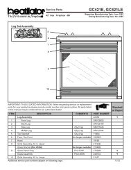
RRCastile-B FS Pellet StoveCastile-B FS Pellet StoveE. Optional Log Set Placement InstructionsF. Thermostat InstallationCAUTIONLogs are FRAGILE. Use extreme care when handling orcleaning logs.2 PIECE LOG SET INSTALLATION1. Open door to expose the firebox.2. Install the left log first and then the right log. Figure 20.13. Lean the logs against the cast iron brick in the back ofthe firebox.4. Push the logs to the far left and far right against thesides of the firebox. Figure 20.2.5. To clean the logs, use a vaccum cleaner and a softbrush attachment or a paint brush.1. A 12 volt AC thermostat is required to operate this pelletappliance. You may use the included wall mount thermostator purchase an optional programmable thermostator remote control. It is equipped with an adjustableheat anticipator. The current rating is .05 amps. Theanticipator needs to be adjusted to the lowest settingavailable.2. When mounting a thermostat on a wall, be sure to followyour thermostat installation instructions carefully.NOTE: Thermostat must be mounted level foraccurate readings. The thermostat should bemounted on an inside wall and not in direct linewith the appliance convection air.NOTE: If the thermostat is located too close to theappliance, you may need to set the temperaturesetting slightly higher to maintain the desiredtemperature in your home.3. There is a 4 screw terminal block located on the backlower right corner of the stove directly above the powercord inlet. The center 2 screws are for the thermostatwires.CautionShock hazard.• Do NOT remove grounding prong from plug.• Plug directly into properly grounded 3 prong receptacle.• Route cord away from appliance.• Do NOT route cord under or in front of appliance.FUSEFuseTERMINAL BLOCKCENTER 2 SCREWS FORTHERMOSTAT WIRESFigure 20.1POWER OUTLETFigure 20.2NOTE:Due to the abrasive nature of a pellet appliance fire, thelogs are not covered under warranty. Any placement variationother than shown here can cause excessive heat andshall void the appliance warranty.Figure 21.1Page 20 7021-130D January 21, 2013January 21, 2013 7021-130D Page 21
RRCastile-B FS Pellet StoveCastile-B FS Pellet Stove8Operating InstructionsA. Fuel Size, Material and Storage1. Wood PelletsFuel pellets are made from sawdust or wood by-products. If thesource material is hardwood, they can have a higher mineralcontent, creating more ash. Fuels containing bark will alsohave higher ash content. Minerals and other noncombustiblematerials such as sand will turn into a hard, glass-like substancecalled a clinker when heated to the extreme temperatures ourfirepot reaches. This is what forms clinkers in the bottom of thefirepot. Trees from different areas will vary in mineral content.That is why some fuels produce more clinkers than others.Pellets are manufactured in either 1/4 inch or 5/16 inch (6-8mm)diameter and should be no more than 1-1/2 inches (38mm)in length. Pellet lengths may even vary by lot from the samemanufacturer which is why the feed rate may need to be adjustedoccasionally. If you burn pellets longer than 1-1/2 inches(38mm) you may have an inconsistent fuel feed rate and/ormissed ignitions.Pellet fuel quality can greatly fluctuate. We recommend usingpremium grade fuel with ash content less than 1%. Even in somefuel labeled “premium” ash content can vary from bag to bagand possibly exceed 1%. High ash fuel, or lack of maintenance,can cause the firepot to fill up and thus create a potential forsmoking, sooting and possible hopper fires.Always burn dry fuel. Burning fuel with high moisture contenttakes heat from the fuel and tends to cool the appliance,robbing heat from your home. Damp pellet fuel can clog thefeed system.We recommend that you buy fuel in multi-ton lots wheneverpossible. Buying large quantities of fuel at once will greatlyreduce the number of times the feed adjustments will need to bemade. However, we do recommend trying various brands beforepurchasing multi-ton lots to ensure your satisfaction.WARNINGFire Risk.• High ash fuels, or lack of maintenance, cancause the firepot to overfill. Follow propershutdown procedure if ash buildup exceedshalf way point in firepot.• Failure to do so could result in smoking,sooting and possible hopper fires.2. Shelled Field CornExtensive factory and field testing has demonstrated shelledfield corn to be an efficient and very economical fuel. Werecommend the use of a 50-50 blend of corn and wood pellets.The only change in operation is that the feed rate may requirea slight adjustment. The BTU output of the appliance variesslightly compared to pellets, depending on the quality of theShelled Field Corn (Cont’d)corn used. In cases where it is acceptable for the applianceto run full time, 100% corn will work after the fire has beenstarted using wood pellets.When purchasing corn to burn in your appliance, read theingredient label very carefully. Do NOT purchase fuelthat contains any additives such as oils (i.e. soybean oil)and meals as it will result in poor unit performance. If youare buying corn the only ingredient that should be listedis corn.Shelled field corn must be 15% or less moisture content.The corn must be clean and free from debris. Never burncorn straight from the field. Stalk parts, excessive fines andcob remnants, etc. will clog the auger mechanism. Cornwith excessive grain dust must be screened by sifting with3/16 (4.76mm) inch mesh screening.Do not burn treated seed corn in your appliance. Seed cornis treated with chemical pesticides that are harmful or fatalif swallowed; therefore, seed corn is dangerous to have inthe house, expecially where children can reach it. Burningtreated seed corn in your appliane will void your warrantyand will destroy the exhaust system on the unit.When changing to a different fuel, be sure to empty thehopper of the previous fuel and vacuum the hopper beforeyou fill it with the new fuel.WARNINGRisk of Chemical Poisoning.• Do Not burn treated seed corn• Chemical pesticides are harmful or fatal ifswallowed• Burning treated seed corn will void yourwarranty3. StorageWood pellets should be left in their original sealed bag untilusing. This will prevent moisture absorption.Shelled corn should be stored in a tight container where itwill not absorb moisture from damp or wet floors. This willalso prevent rodents from becoming a problem.Do not store any pellet fuel within the clearancerequirements or in an area that would hinder routine cleaningand maintenance.B. General Operating Information1. Thermostat Calls For HeatThe appliance is like most modern furnaces; when thethermostat calls for heat, your appliance will automaticallylight and deliver heat. When the room is up to temperatureand the thermostat is satisfied, the red call light will go offand the appliance will shut down.2. Heat Output ControlsThis appliance is equipped with a heat output controlswitch that has three settings or burn rates; low, mediumand high. The appliance will turn on and off as thethermostat demands. When the thermostat calls for heat,the appliance will start up at the burn rate for which it isset. If the appliance is set at one of the lower settings, itwill run quieter but take longer to heat up an area than if itwere set at a higher burn rate. Regardless of the burn rate,when the area is warm enough to satisfy the thermostat,the appliance will shut off.Figure 23.1Reset ButtonWARNINGHeat Output SwitchHighMedLowResetButtonFire Hazard.Keep combustible materials, gasolineand other flammable vapors and liquidsclear of appliance.• Do NOT store flammable materials in the appliance’svicinity.• Do NOT use gasoline, lantern fuel, kerosene,charcoal lighter fluid or similar liquids tostart or “freshen up” a fire in this heater.• DO NOT BURN GARBAGE OR FLAMMABLE FLUIDSSUCH AS GASOLINE, NAPHTHA OR ENGINE OIL.• DO NOT USE CHEMICALS OF FLUIDS TO START THEFIRE.• Keep all such liquids well away from the heater while it is inuse.• Combustible materials may ignite.C. Before Your First Fire1. First, make sure your appliance has been properlyinstalled and that all safety requirements have been met.Pay particular attention to the fire protection, venting andthermostat installation instructions.2. Double check that the ash drawer and firebox areempty!3. Check the position of the thermocouple, located abovethe firepot, and make sure that it protrudes approximately3/4 inch (19mm) into the firepot.4. Close the front door.IMPORTANT DETAIL: The tip of the thermocouple mustbe in contact with the inside end of the thermocouplecover or missed ignitions can occur.D. Starting Your First Fire1. A thermostat is required for proper operation of thisappliance, except for corn. At this time, fill the hopperwith pellets, set the thermostat to its lowest setting. Plugthe power cord into nearby outlet.2. The exhaust blower will stay on for approximately 18minutes even though the thermostat is not calling for heat.This is normal.3. Locate the heat output control switch mounted on theback of the appliance in the upper right corner. Figure23.1. Turn it to the “high” setting by pushing the top ofthe control switch in and then adjust the thermostat to itshighest setting. Remove the right side panel and the redcall light located to the left of the control box will be on.Figure 24.1 on page 24. This indicates the thermostat iscalling for heat.4. The fuel feed system and the igniter should now be on.5. For your first fire it will be necessary to press the resetbutton once approximately 2 minutes after start up andagain in 5 minutes. This will fill the feed system and allowthe appliance to begin dropping pellets. The appliancewill continue to run as long as the thermostat is calling forheat.6. Once the appliance has ignited, let it burn for approximately15 minutes, then set the thermostat to the desired roomtemperature. Adjust the heat output control switch to thedesired setting.Page 22 7021-130D January 21, 2013January 21, 2013 7021-130D Page 23
RRCastile-B FS Pellet StoveCastile-B FS Pellet StoveE. Fire CharacteristicsA properly adjusted fire with the heat output control switchset on “high” has a short active flame pattern that extendsout of the firepot approximately 4 inches (102mm). If the firehas tall flames with black tails and seems somewhat lazy,the feed rate will need to be reduced. This is done by slidingthe fuel adjustment control rod down, which will reduce thefeed. If the fire is not 4 inches (102mm) tall, slide the fueladjustment control rod up to increase the feed. A mediumand low setting will give a shorter flame. The flame will riseand fall somewhat. This is normal.F. Iginition Cycles1. During each ignition cycle, it is normal to see somesmoke in the firebox. The smoke will stop once thefire starts.2. The convection blower will automatically turn on afteryour appliance has reached the set temperature onthe “high” setting. This blower transfers heat from yourappliance into the room, and will continue to run afterthe thermostat has stopped calling for heat until theappliance has cooled down.3. Occasionally the appliance may run out of fuel and shutitself down. When this happens, the red call light willbe on. Figure 24.1. To restart it, fill the hopper andpress the reset button. (See Figure 23.1, page 231).When you press the reset button the red call light willgo out. Release the button and the light will come backon. You should see a fire shortly. If not, follow theinstructions on page 23, of “Starting Your First Fire”.G. Feed Rate Adjustment InstructionsThe feed adjustment control rod is factory set, and shouldbe adequate for most fuels. However, if the flame height istoo high or too low, you will need to adjust the feed rate. Waituntil the appliance has been burning for 15 minutes beforemaking your adjustments and allow 15 minutes for feedadjustment to take effect.1. Loosen the set screw 1/4 to 1/2 turn during set-upof appliance. This will allow movement of the feedadjustment control rod. Do not re-tighten set screw.Figure 24.2.2. Loosen the thumb screw.3. Adjust the feed adjustment control rod upward towardsthe "+" symbol to increase the feed rate and flame heightor down towards the "-" symbol, to decrease the feed rateand flame height.4. Re-tighten the thumb screw.Feed AdjustmentControl RodThumb ScrewIncreaseSet ScrewDecreaseH. Frequently Asked QuestionsISSUESSOLUTIONS1. Metallic noise. 1. Noise is caused by metal expanding and contracting asit heats up and cools down, similar to the sound producedby a furnace or heating duct. This noise does notaffect the operation or longevity of your appliance.2. Ash buildup on glass. 2. This is normal. Clean the glass.3. Glass has turned dirty. 3. Excessive build up of ash. The lower burn settings willproduce more ash, the higher burn settings produceless. The more it burns on low the more frequent cleaningof the glass is required.4. Fire has tall flames with black tails and is lazy. 4. The feed rate needs to be reduced or the firepot needscleaning. Heat exchanger or exhaust blower needscleaning.5. Smokey start-up or puffs of smoke from the airwash. 5. Either the firepot is dirty or there is too much fuel atstart-up and not enough air. Close down feed rate 1/4inch at a time until this no longer happens.6. Large flame at start-up. 6. This is normal. Flame will settle down once the fire isestablished.CAUTIONOdors and vapors released during initial operation.• Curing of high temperature paint.• Open windows for air circulation.Odors may be irritating to sensitive individuals.Red Call Light islocated on top ofJunction Box behindthe Control Box.Figure 24.2WARNINGBack side of FirepotFire RiskDo NOT operate appliance:• With appliance door open.• Firepot floor open.• Cleaning slide plates open.Do NOT store fuel:• Closer than required clearances to combustiblesto appliance• Within space required for loading or ashremoval.Firepot floor left openFigure 25.1 - DO NOT LEAVE FIREPOT FLOOR OPENControlBoxFigure 24.1Page 24 7021-130D January 21, 2013January 21, 2013 7021-130D Page 25
RRCastile-B FS Pellet StoveCastile-B FS Pellet Stove9TroubleshootingWith proper installation, operation, and maintenance your appliance will provide yearsof trouble-free service. If you do experience a problem, this troubleshooting guidewill assist a qualified service person in the diagnosis of a problem and the correctiveaction to be taken. This troubleshooting guide can only be used by a qualifiedservice technician.Symption Possible Cause Corrective ActionPlug in appliance - Noresponse.No current to outlet.7 amp fuse defective.#3 snap disc tripped or defective.Control box defective.Check circuit breaker at service panel.Replace fuse.Reset or replace snap disc.Replace control box.Call light on. No fire.No fuel in firepot.Out of fuel.#2 snap disc may be defective.Vacuum switch not closing, no vacuum.Control box defective.Check hopper. Fill with fuel.Replace snap disc.Check exhaust blower is plugged in andoperating.Check vacuum switch is plugged in.Check vacuum hose is in good condition,clear and connected at both ends.Check thermocouple is in good conditionand plugged in properly.Make sure venting system is clean.Make sure front door is closed.Replace control box.Call light on. No fire.Partially burned fuel infirepot.Firepot clean-out plate not closed.Firepot is dirty (missed ignition).Check that firepot clean-out plate is fullyclosed.Clean firepot. Make sure there is no clinkerin the firepot.Clinkers may have to be broken up withfirepot scraper tool or other means.Call light on. No fire.Unburned pellets infirepot.Slow or smoky start-up.Firepot clean-out plate not closed.Firepot is dirty.Ignition hole blocked.Igniter not working.Control box defective.Firepot clean-out plate not closed.Firepot is dirty.Excessive amount of fuel at start-up.Check that firepot clean-out plate is fullyclosed.Clean firepot. Make sure there is not aclinker in the firepot. Clinkers may have tobe pushed out of firepot with firepot scrapertool or other means.Scrape with solid piece of wire.Remove ash pan to see if igniter is glowingred on start-up.Check igniter wires for good connection.Replace igniter using 1/4 inch male /femalespade connectors.Replace control box.Check that firepot clean-out is fully closed.Clean firepot. Make sure there is not aclinker in the firepot. Clinkers may have topushed out of firepot with firepot scrapertool or other means.Reduce feed rate using feed rate adjustmentcontrol rod located inside hopper.Symptom Possible Cause Corrective ActionSlow or smoky start-up(Cont’d)Dirty exhaust and/or venting system.Check for ash build up in unit, includingbehind rear panels, firebox, heatexchanger, exhaust blower and venting.Feed system fails tostart.No call light. Unitdoes not begin startsequence.Out of fuel.#2 snap disc may be defective.Vacuum switch not closing. No vacuum.Feed system jammed or blocked.Feed spring not turning with feed motor.Feed motor defective or not plugged in.Thermostat not set to a high enough temperature.Snap Disc #3 tripped.No power.Fuse blown.Connections at thermostat and/or appliance notmaking proper contact.Defective thermostat or thermostat wiring.Check hopper, fill with fuel.Replace snap disc. Firebox door must beclosed securely.Check exhaust blower is plugged in andoperating.Check vacuum switch is plugged in.Check vacuum hose is in good condition,clear and connected at both ends.Check thermocouple is in good conditionand plugged in properly.Make sure venting system is clean.NOTE: High winds blowing into the ventingsystem can pressurize the fireboxcausing loss of vacuum.Empty hopper of fuel. Use a wet/dryvacuum cleaner to remove remaining fuel,from hopper, including feed tube.Check feed chute for obstructions.Loosen 2 feed assembly mounting screwsand lightly shake feed assembly.Check that set screw is tight on feedspring shaft at end of feed motor.Check connections on feed motor, replaceif defective.Adjust thermostat above room temperature.Reset snap disc.Connect to power.Replace fuse.Check connections at thermostat andappliance.Replace thermostat or wiring.NOTE: To test thermostat and wiring, usea jumper wire at the thermostat block onthe unit to by-pass thermostat and wiring.Control box defective.Replace control box.Unit fails to shut off. Call light on. Turn thermostat off.If call light does not go out, disconnectthermostat wires from unit. If call lightdoes go out, thermostat or wires aredefective.Page 26 7021-130D January 21, 2013January 21, 2013 7021-130D Page 27
RRCastile-B FS Pellet StoveCastile-B FS Pellet StoveSymptoms Possible Cause Corrective Action#1 snap disc defective.Replace snap disc.Convection blower fails tostart.Exhaust blower fails tostart or does not shut off.Large, lazy flame, orangecolor. Black ash on glass.Nuisance shutdowns.Appliance calls for heat.Call light illuminates.Exhaust blower starts.No feed or igniter.Blower not plugged in.Blower is defective.Control box is defective.Blower not plugged in.Blower is clogged with ash.Blower is defective.Control box is defective.Dirty appliance.Poor fuel quality, high ash content.Firepot clean-out plate not completelyclosed.Excessive amount of fuel.Low flame.Sawdust buildup in hopper.Feed motor is reversing.Defective thermocouple.Defective control box.Firepot more than 1/2 full.Thermocouple is defective or not properlyplugged in.Defective control box.Check that blower is plugged into wire harness.Replace blower.Replace control box.Check that blower is plugged into wire harness.Clean exhaust system.Replace blower.Replace control box.Clean unit, including firepot, heat exchangersand venting system. Remove stainlesssteel baffle from firebox to clean ash fromon top of baffle. Clean behind rear brickpanels. Change fuel brand to premium.Check that firepot clean-out plate is fullyclosed.Reduce feed rate using feed rate adjustmentcontrol rod located inside hopper.Increase feed by opening feed rate adjustmentcontrol rod located inside hopper.Clean hopper, see page 30.Check for good connections between feedmotor and wire harness.Replace thermocouple.Replace control box.See page 33 for detailed instructions for“High Ash Fuel Content Management”Check connections on thermocouple orreplace if defective.A flashing yellow light on the control boxindicates a problem with the thermocouple.Replace control box.Page 28 7021-130D January 21, 201310Maintaining & Servicing Your ApplianceA. Proper Shutdown ProcedureCautionShock and Smoke Hazard• Turn down thermostat, let appliance completelycool and exhaust blower must be off. Now youcan unplug appliance before servicing.• Smoke spillage into room can occur if applianceis not cool before unplugging.• Risk of shock if appliance not unplugged beforeservicing appliance.Follow the detailed instructions found in thissection for each step listed as referenced in thechart below.B. Quick Reference Maintenance ChartC. General Maintenance1. Types of FuelDepending on the type of fuel you are burning will dictate howoften you have to clean your firepot.If the fuel you are burning has a high dirt or ash content oryou are burning shelled field corn, it may be necessary toclean the firepot more than once a day.Dirty fuel will cause clinkers to form in the firepot. A clinkeris formed when dirt, ash or a non-burnable substance isheated to 2000°F (1093°C) and becomes glass-like. See“C” page 33 in this section for more details on fuels withhigh ash content.Figure 29.1 - ClinkerCleaning or Inspection Frequency Daily Weekly Monthly YearlyAsh Pan Every 5 bags of fuel OR XAsh Removal from FireboxMore frequently depending on ORXthe fuel type or ash build-upBeneath Heat Exchanger Every 1 ton of fuel OR XBlower, Combustion (Exhaust)More frequently depending on OR Xthe fuel typeBlower, ConvectionMore frequently depending on OR Xthe operating environment.Door Latch Inspection Prior to heating season OR XExhaust PathMore frequently depending on ORXash build-upFirebox - Prepare for Non-Burn Season At end of heating season OR XFirepot - Burning pellets - hardwood Every 3 bags OR XFirepot - Burning pellets - softwood Every 5 bags OR XFirepot - Burning Corn Every 1 bag OR XGlassWhen clear view of firepot ORXbecomes obscureHeat Exchanger & Drop Tube Every 1 ton of fuel OR XHopperEvery 1 ton of fuel or when ORXchanging fuel typesTop Vent AdapterMore frequently depending on ORXthe fuel type or ash build-upVenting SystemMore frequently depending onthe fuel typeORXNOTICE: These are recommendations. Clean more frequently if you encounter heavy build-up ofash at the recommended interval or you see soot coming from the vent. Not properlycleaning your appliance on a regular basis will void your warranty.January 21, 2013 7021-130D Page 29Clinker
RRCastile-B FS Pellet StoveCastile-B FS Pellet Stove2. Cleaning Firepot with Cleaning Rod & FirepotScraper• Frequency: Daily or more often as needed• By: Homeownera. The appliance must be in complete shutdown and cooland the exhaust blower off. If you are just cleaning thefirepot, there is no need to unplug the appliance.b. Pull firepot cleaning rod OUT a couple of times to helpshake debris loose. If rod is hard to pull, it may benecessary to use your firepot clean-out tool to chipaway material that has built up on the bottom plate ofthe firepot and to push out any clinkers. Larger clinkersmay have to be removed from the top of the firepot.Corn clinkers can be especially difficult to break up.c. The firepot floor plate must be fully closed whenfinished. See Figure 25.1 on page 25.Ash Removal from Firebox (Cont’d)e. The 2 cleaning slide plates must be fully closed whencleaning is complete. See Disposal of Ashes.7. Cleaning Heat Exchanger Chambers & Drop Tube• Frequency: Monthly or every 1 ton of fuel• By: HomeownerHeat Exchanger TubesWARNINGFire Risk• NEVER pull firepot cleaning rod or cleaningslide plates out when appliance is operating.• The cleaning slide plates must be fullyCLOSED when appliance is operating.•. Hot pellets may fall into ashpan and start a fireor mis-starts due to lack of vacuum.3. Ash Removal from Firebox• Frequency: Weekly or more frequently depending onash build-up.• By: Homeownera. There must not be any hot ashes in the firebox duringcleaning so allow the appliance to completely cool.The firebox ash should be removed every time thefirepot is cleaned. Frequent cleaning of the ash in thefirebox will help slow down the build-up of ash in theexhaust blower and vent system.b. Plug in your appliance, if unplugged, and turn thethermostat on and immediatley shut it off to start theexhaust blower on its cycle time. It will pull fly ash outthe exhaust instead of into the room.c. Open cast hinged face. Directly underneath thefirebox door and to the left and right of the firepot are 2cleaning slide plates with finger holes. Pull both slideplates out and then open the glass door. Sweep theremaining ash from the firebox into the 2 open holes.A paint brush works well for this. Close slide plates.d. This ash is deposited in the same ash pan as thefirepot debris. The ash pan should be emptied everytime you clean the firebox. Remember to placethe ash and debris into a metal or noncombustiblecontainer.WARNINGDisposal of Ashes• Ashes should be placed in metal containerwith tight fitting lid.• Ashes should be retained in closed containeruntil all cinders have thoroughly cooled.4. Cleaning Ash Pan• Frequency: Weekly or every 5 bags of fuel• By: HomeownerLocate the ash pan underneath the firepot. Open thebottom ash door and slide the ash pan straight out.Empty into a non-combustible container and re-installash pan. See Disposal of Ashes.5. Disposal of Ashes• Frequency: As needed• By: HomeownerAshes should be placed in a steel container with atight-fitting lid. The container of ashes should be movedoutdoors immediately and placed on a non-combustiblefloor or on the ground, well away from combustiblematerials, pending final disposal.If the ashes are disposed of by burial in soil or otherwiselocally dispersed, they should be retained in the closedcontainer until all cinders have thoroughly cooled. Otherwaste shall not be placed in this container.6. Cleaning the Hopper• Frequency: Monthly or after burning 1 ton of fuel• By: HomeownerAfter burning approximately 1 ton of fuel you will need toclean the hopper to prevent sawdust build-up.A combination of sawdust and pellets on the augerreduces the amount of fuel supply to the firepot. Thiscan result in nuisance shutdowns and mis-starts.a. The appliance must be in complete shutdown. Allowthe appliance to completely cool down.b. Empty the hopper of any remaining pellets.c. Vacuum the hopper and feed tube.WARNINGHeat exchanger cleaning rods may be warmto the touch. For safety purposes weargloves.Do not pull heat exchanger cleaning rodswhile appliance is operating.Push cleaning rods IN when done, DO NOTleave cleaning rods OUT. Injury can occur.The amount of ash buildup in the firepot will be a goodguide to determine how often you should clean the heatexchangers.a. Allow the appliance to completely cool down beforepulling the cleaning rods. Turn the thermostat on andthen immediately off to start the exhaust blower on itscycle time. It will pull fly ash out the exhaust insteadof into the room. Open the cast hinged face to accessthe 2 cleaning rods. Figure 31.1.b. Locate the 2 rods directly underneath the heatexchanger tubes. Rods are bent at a 90° angle foreasy handling.c. To clean, pull the rods straight out until it stops,approximately 5-1/2 inches (140mm). Slide the rodsOUT and IN a couple of times.8. Cleaning the Exhaust Path• Frequency: Yearly or more frequently depending onash build-up.• By: Homeownera. Appliance must be completely cool.b. Open cast hinge face. Remove right brick andthoroughly vacuum the area and continue throughoutthe rest of the firebox.c. Replace right brick and close cast hinge face.NOTE: There are heavy duty vacuum cleaners specificallydesigned for solid fuel appliance cleaning.Figure 31.1Cleaning Rods9. Cleaning Beneath Heat Exchanger• Frequency: Monthly or after burning 1 ton of fuel• By: Homeownera. Be sure the appliance is allowed to cool, has beenunplugged and the exhaust blower is offb. A more thorough cleaning is needed to remove theexcess ash that is left behind from the use of thecleaning rods for the heat exchanger tubes.c. The ash will be resting on the back of the baffle.This will require removing the cast baffle. Pleaserefer to page 33 for a detailed explanation of removingthe baffle.10. Soot and Fly Ash: Formation & Need for Removalin Exhaust Venting System.• Frequency: Yearly or more frequently depending onash build-up.• By: Qualified Service Technician/HomeownerBe sure the appliance is allowed to cool, has been unpluggedand the exhaust blower is off.The products of combustion will contain small particles of flyash. The fly ash will collect in the exhaust venting systemand restrict the flow of the flue gases.At start-up if there is incomplete combustion, or if there is ashutdown or incorrect operation of the appliance it will leadto some soot formation. This will collect in the exhaust ventingsystem.The venting system may need to be cleaned at least once ayear or more often depending upon the quality of your fuelor if there is a lot of horizontal pipe sections. Ash will buildup more quickly in the horizontal sections.Page 30 7021-130D January 21, 2013January 21, 2013 7021-130D Page 31
RRCastile-B FS Pellet StoveCastile-B FS Pellet Stove11. Cleaning Convection Blower - Requires NoLubrication• Frequency: Yearly or as needed• By: Qualified Service Technician / HomeownerThe convection blower is located at the bottom rear ofthe stove. It is house inside the screen box. See page31 for detailed instructions on removing the blower.The blower has two impellers, one on each side of themotor. They should be cleaned at least once each yearor more often as needed.12. Cleaning Exhaust Blower - Requires NoLubrication• Frequency: Yearly or as needed• By: Qualified Service Technician• Task: Contact your local dealer.13. Door Latch Inspection• Frequency: Prior to heating season• By: HomeownerThe door latch is non-adjustable but the gasketing betweenthe glass and firebox should be inspected periodically tomake sure there is a good seal.15. Cleaning the Glass• Frequency: When clear view of the firepot becomesobscure• By: Homeownera. Appliance must be completely cool before cleaningglass.b. Use a damp paper towel or any non-abrasive glasscleaner. Wipe off with dry towel.CAUTIONHandle glass assembly with care.When cleaning glass:• Avoid striking, scratching orslamming glass.• Do NOT clean glass when hot.• Do NOT use abrasive cleaners.• Use a hard water deposit glass cleaner on white film.• Refer to maintenance instructions.WARNINGD. High Ash Fuel Content Maintenance• Frequency: When the ash build-up exceeds morethan half way up the firepot.• By: HomeownerPoor quality pellet fuel, or lack of maintenance, can createconditions that make the firepot fill quickly with ashes andclinkers.This condition makes the appliance susceptible to overfillingthe firepot with pellets which may result in smoking, sootingand possible hopper fires. Figure 33.1 shows an examplewhere the firepot overfills, pellets back up into the feed tubeand ash has accumulated in the firebox.An inefficient and non-economical method of burning of fuelcaused by poor quality pellet fuel is shown in Figure 33.2.The correct flame size when good quality, premium pelletfuel is burned is shown in Figure 33.3.If the ash buildup exceeds the half way point in the firepotIMMEDIATE ATTENTION AND CLEANING IS REQUIRED.E. Soot or Creosote FireFigure 33.1Incorrect14. Cleaning the Top Vent Adaptera. The appliance must be in complete shutdown and theexhaust blower should be off. Allow the appliance tocompletely cool down.b. Open the clean out cover. See Figure 30.1.c. Sweep out any ash build-up.NOTE: There are heavy duty vacuum cleaners specifiicallydesigned for solid fuel appliance cleaning.Handle glass with care.• Inspect the gasket to ensure it isundamaged.• Do NOT strike, slam or scratch glass.• Do NOT operate appliance with glassassembly removed.• Do NOT operate with glass cracked, broken orscratched.Establish a routine for the fuel, wood burner and firing technique.Check daily for creosote build-up until experienceshows how often you need to clean to be safe. Be aware thatthe hotter the fire the less creosote is deposited, and weeklycleaning may be necessary in the mild weather even thoughmonthly cleaning may be enough in the coldest months.Contact your local municipal or provincial fire authority forinformation on how to handle a chimney fire.Tall, Lazy Flame, Orange in ColorFigure 33.216. Preparing Firebox for Non-Burn Season• Frequency: Yearly• By: Homeownera. Be sure the appliance is allowed to cool, has beenunplugged and the exhaust blower is off.b. Remove all ash from the firebox and vacuum thoroughly.c. Paint all exposed steel, including cast-iron.• Use the Touch-Up paint supplied with the appliance;or;• Purchase paint from your local dealer.• Must use a high-temperature paint made specificiallyfor heating appliances.In the event of a soot or creosote fire, close the fireboxdoor, exit the building immediately and contact the properfire authorities.DO NOT under any circumstances re-enter the building.CorrectCorrect Flame Size, Yellow/White in ColorFigure 33.3Figure 32.1Clean-Out CoverPage 32 7021-130D January 21, 2013January 21, 2013 7021-130D Page 33
RRCastile-B FS Pellet StoveCastile-B FS Pellet StoveF. Blower Replacement1. Combustion Blower ReplacementNOTE: The convection blower must be removedbefore the exhaust blower can be removed.a. Turn down thermostat, let appliance completely cool andthen unplug appliance before servicing.b Remove both side curtains by loosening 2 screws (donot remove) and pull side panels away.c. Remove 4 screws from the back screen and pivot the topof the screen toward you leaving the bottom attached tostove. Figure 34.1.d. Remove 2 screws to remove the thermostat block anddisconnect the 2 yellow wires.e. Remove the 2 screws from the power inlet and rotate itthrough the hole and out of the screen, leaving the wiresattached.f. Disconnect the vacuum hose and both wires (orangeand red) from the vacuum switch attached to the rearscreen.g. Remove both wires from exhaust blower (blue anddouble white).h. Remove 6 screws using a flathead screwdriver or a 1/4"nutdriver. Retain screws for use on replacement blower.Figure 34.2.i. Remove exhaust blower and gasket.j. Install new gasket and blower. Discard blower housingif not needed.k. Re-install in reverse order.Remove 6 screwsFigure 34.2F. Blower Replacement (Cont’d)2. Convection Blower Replacementa. Turn down thermostat, let appliance completely cooland then unplug appliance before servicing.b. The convection blower is located at the bottom rearof the appliance and is housed inside a screen box.Remove the 2 screws facing forward in the center ofthe blower chamber at the very back of the appliance.c. If an outside air kit is installed on the appliance, thesescrews attach the intake air channel piece of the outsideair kit to the appliance. Remove the 2 screws and pullbackwards on the channel and it will slide down andaway from the appliance. The air channel, collar andoutside air hose will be removed as one piece.d. There are 2 screws on each side of the housing. Loosenall 4 screws, but do not remove them. Lift the blowerhousing up slightly and slide towards you. Figure35.1.e. Remove the left side panel by loosening 2 screws (do notremove) and pull side panel away. Unplug the 2 blackblower wires by disconnecting the spade connectors.f. To remove blower from the housing, remove 2 screwsin the front of the housing and very carefully bend the2 housing sides out and bend the back of the housingaway from the blower. This allows for room to accessthe back 2 screws and nuts (4 total) that is securing theblower to the housing.g. Remove blower and replace with new blower.e. Re-install in reverse order.G. Baffle & Brick Set Removal1. Follow proper shutdown procedures in Section 10.2. The top baffle has a hook on the bottom left side thatrests on the top lip of the cast brick. There is a tab onthe bottom right side that hooks into the side bracket.Remove the top baffle by first pulling the baffle forwarduntil back edge drops down. Then slide baffle back untilthe front edge clears the shelf that it had been resting on.Figure 35.23. The top baffle must be removed before you can removethe right and left brick. Remove the right brick by holdingtop lip of brick and lifting up, then push outside edgeback. Slide brick to the right until it is flush with the firebox.Rotate the inside edge of the brick forward and removebrick. Repeat for left brick. Figure 35.3.Figure 35.2Hook onleft sideTab onright sideSide Screws,Loosen Do NotRemoveSide Screws,Loosen Do NotRemoveFigure 34.3CombustionBlowerRemove left sidepanel and disconnectblower wiresRemove Right& Left BrickFigure 35.3Remove back screws andbend top back leaving itattached at the bottomRight BrickRemovedFigure 34.1Loosen (do not remove) 2screws on each side and liftoff blower housingConvection Blower& HousingVacuumExhaust AreaFigure 35.1Figure 35.4Page 34 7021-130D January 21, 2013January 21, 2013 7021-130D Page 35
RRH. Igniter ReplacementIgniterBracketFigure 36.11. Turn down thermostat, let the appliance completelycool and then unplug appliance before servicing.2. Open the ash door and remove the ash pan. Removethe left side panel by loosening 2 screws (do notremove) and pull side panel away.3. The wire leads to the igniter are connected to thewire harness (black wires) with 1/4 inch male / femalespade connectors. Disconnect the spade connections.Loosen the thumb screw and slide igniter out.4. Install new igniter into the chamber and tighten thethumb screw.5. Re-connect the wires to the 2 leads with the spadeconnectors. Double check that the igniter wires areclear of any movement, i.e. ash pan, firepot cleaningrod, cleaning slide plates, etc.6. Re-install the ash pan, close the ash removal door.I. Glass ReplacementIgniterThumb ScrewWARNING• Glass is 5mm thick high temperature heatresistantceramic glass.• DO NOT REPLACE with any other material.• Alternate material may shatter and causeinjury1. Open the face and remove door from the applianceby lifting door off of hinge pin and lay on a flat surfaceface down.2. Using a screwdriver, tap the bottom of the rope retainerrod to push it up out of the hole. The top end of therod will slide up. Swing the rod toward you from thebottom and remove the rod. Repeat for other side.3. Remove old glass and replace with new glass.Figure 36.2Castile-B FS Pellet Stove4. Slide the retainer rod into the top hole first, and thenline up the bottom crimped end with the hole in thedoor. The crimped end must be parallel with the glassin order to insert it into place. Figure 36.2.GlassRope RetainerRodsJ. Damaged/Broken ComponentReplacementSlide topend in firstCrimped endat the bottomCrimped end must beparallel with the glass1. Replacement of broken or damaged componentsshould only be completed by a trained or qualifiedtechnician.2. In the event that you find a damaged component,please contact your local dealer, to send a servicetechnician to complete the removal and replacementof the parts.Castile-B FS Pellet Stove11Reference MaterialsWhen describing the location of a component,it is always AS YOU FACE THE FRONT OFTHE APPLIANCE.A. Component Function1. Control Boxa. The control box is located on upper right side ofappliance, behind the right side panel and above thevacuum switch.b. There is a light located inside of the control box. Theinternal light will turn green when the appliance hasreached a temperature of 175 o F (79°C) in the firepot.and will turn red when it reaches 600 o F (315°C).c. There is also an internal blue light located in the upperleft corner of the control box. When you plug in theappliance the blue light will automatically start blinking4 times in a row for 60 seconds and then will stop.NOTE:Do NOT open the control box. This will void thewarranty. FolIow proper shutdown procedures first ifyou need to plug in or remove the control box.2. Convection BlowerThe convection blower is mounted at the bottom rear of theappliance. There are 2 impellers, one on each side of themotor. The convection blower pushes heated air through theheat exchange system into the room.3. Combustion BlowerThe combustion blower is located on the right side ofappliance and is designed to pull the exhaust from theappliance and push it out through the venting system.4. Feed SystemThe feed system is located on the right side of the applianceand can be removed as an entire assembly. The assemblyincludes the feed motor, mounting bracket, bearing and feedspring (auger). The hollow feed spring (auger) pulls pelletsup the feed tube from the hopper area and drops them downthe feed chute into the firepot.5. FirepotThe firepot is made of high quality ductile iron and has acleaning pull-out rod. The floor of the firepot opens forcleaning when you pull out the rod. Be sure that the floorreturns to a completely closed position or your appliance willnot operate properly.6. FuseThe fuse is located on the front of the junction box on theright side of appliance. The fuse will blow should a shortoccur and shut off power to the appliance.7. Heat ExchangersThe heat exchangers transfer hot air from the exhaust systeminto convecton air. Remove the stainless steel top baffle toaccess the heat exchangers. There are 2 clean out rodslocated under the heat exchangers.8. Heat Output SwitchThe heat output switch is located on the upper right rearcorner. The funtion of the heat ouput switch is to regulatethe burn rates; low, medium and high settings.9. Hopper SwitchThe hopper switch is located in the upper right hand cornerof the hopper. This switch is designed to shut down the feedmotor whenever the hopper lid is opened.10. IgniterThe igniter is mounted on the base of the firepot. Combustionair travels over the red hot igniter creating super heated airthat ignites the pellets.11. Junction Box And Wiring HarnessThe junction box is located on the right side of the appliance,behind the right side panel. The junction box and wiringharness are replaced as one component.12. Power SupplyThe power outlet is located on the lower right side of theappliance on the front of the junction box. Check the wallreceptacle for 120 volt, 60 Hz (standard current). Make surethe outlet is grounded and has the correct polarity. A goodsurge protector is recommended. When operating with agenerator you need a least 600 watts of power, or with aninverter at least 800 watts of power available for the applianceduring the start cycle.13. Red Call LightThe red call light is on the front of the junction box, behindthe control box. The function of the red call light is to indicatethat the thermostat is calling for heat.14. Reset ButtonThe reset button is located on the back of the appliance onthe upper right corner of the side panel under the heat outputcontrol switch. The function of the button is to momentarilyopen the thermostat circuit, which restarts the system.15. ThermocoupleThe thermocouple is located on top of the firepot insidethe thermocouple cover (ceramic protection tube). Thethermocouple sends a millivolt signal to the control boxindicating the preset temperatures of the green and red lightshave been obtained.Page 36 7021-130D January 21, 2013January 21, 2013 7021-130D Page 37
RRCastile-B FS Pellet StoveCastile-B FS Pellet Stove16. ThermostatThe appliance is designed to run on a 12 volt AC thermostat.The heat anticipator should be set on the lowest settingavailable.17. Snap Disc #1 (Convection Blower) 110°FSnap disc #1 is located on the right side of the appliance onthe top of the heat exchanger box. There are 2 purple wiresconnected to it. This snap disc turns the convection blower onand off as needed. Power is always present at snap disc #1.18. Snap Disc #2 (Fuel Delivery Interrupt) 250°FSnap disc #2 is also located on the back side of the feed droptube. There are 2 orange wires connected to it. This snap discwill turn off the feed system which will turn off the applianceif an overfire condition should occur or if the convectionblower should fail to operate. If this occurs the snap disc willautomatically reset itself.19. Snap Disc #3 (Back Burn Protector) 250°FSnap disc #3 is mounted on the back of the auger tube inthe center of the appliance and has a red reset button. Toaccess it remove the right side panel. If the fire tries to burnback into the feed system or push exhaust up the feed tube,this snap disc will shut the entire system off. This disc mustbe manually reset.20. Vacuum SwitchThe vacuum switch is located on the right side of theappliance behind right side panel. This switch turns thefeed system on when vacuum is present in the firebox. Thevacuum switch is a safety device to shut off the feed motor ifthe exhaust or the heat exchanger system is dirty or pluggedor if the firebox door is open.21. Wiring HarnessSee Figure 38.1 below.B. Component LocationsCombustionBlowerReset ButtonHeat Output SwitchHighMedLowResetButtonFeed MotorConvection Blower & HousingFigure 39.1THERMOCOUPLEHEAT OUTPUTSWITCHTHERMOS TATBLOCKHeat Exchanger TubesYELLOWVACUUMSWITCHHOPPERSWITCHSNAPDISC #2CAPACITORFEEDMOTORREDORANGEWHITECleaning RodsBLUEBLACKBLACKYELLOWREDSNAPDISC #1CONVECTIONBLOWERFigure 39.2PURPLEGRAYBLUEBLACKBLACKCOMBUSTIONBLOWERRed Call Light is located ontop of Junction Box behindthe Control Box.CALLLIGHTRESETBUTTONSNAPDISC #3FUSEControl BoxFUSEFuseIGNITORVacuum SwitchTERMINAL BLOCKCENTER 2 SCREWS FORTHERMOSTAT WIRESFigure 38.1POWER OUTLETFigure 39.3Page 38 7021-130D January 21, 2013January 21, 2013 7021-130D Page 39
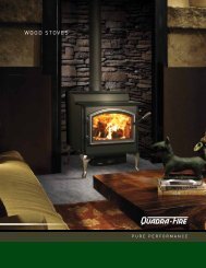
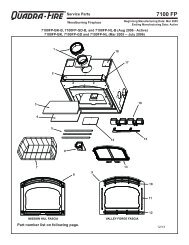
RRC. Exploded Drawing3456728Service PartsCastile Pellet Freestanding Stove<strong>CASTILE</strong>-CSB-B, , <strong>CASTILE</strong>-MBK-B, <strong>CASTILE</strong>-PMH-B<strong>CASTILE</strong>-CWL-B (Oct 2009 thru June 2011)129Castile-B FS Pellet Stove302827Castile-B FSBeginning Manufacturing Date: Oct. 2009Ending Manufacturing Date: Active2322262524Castile-B FS Pellet StoveService PartsIMPORTANT: THIS IS DATED INFORMATION. When requesting service or replacementparts for your appliance please provide model number and serial number. All parts listedin this manual may be ordered from an authorized dealer.Stockedat DepotITEM DESCRIPTION COMMENTS PART NUMBERBlackSRV7021-022MBK1 Hopper Lid AssemblyMahogany SRV7021-022PMHSienna Bronze SRV7021-022CSBWillowSRV7021-022CWLBumper, Rubber Pkg of 12 SRV224-0340/12 YMagnet Round SRV7000-140 YBlack7021-101MBK2 TopMahogany 7021-101PMHSienna Bronze 7021-101CSBWillow7021-101CWL3 Cast Retainer Upper SRV7021-1414 Convection Air Director SRV7021-1235 Hinge Bracket SRV7021-1156 Outer Skin Left SRV7021-1197 Brick, Left / Right, Cast 414-02708 Brick, Center, Cast 414-02609 Cast Retainer Lower Left Assembly SRV7021-018#10 Firepot Assembly and Asscociated PartsCastile-B FSBeginning Manufacturing Date: Oct. 2009Ending Manufacturing Date: Active91021201910.110.510.610.410.71110 210.31810.1 Pull Rod Assembly SRV7021-005Knob, Ash Dump Control Rod 832-30201617Spring, Firepot 200-205010.2 Wing Thumb Screw 8-32 x 1/2 Pkg of 24 7000-223/24 Y141510.3 Heating Element Assembly 18” (Loop Igniter) Pkg of 10 SRV7000-462/10 Y10.4 Firepot Assembly SRV414-5200 YBushing, Firepot 410-8320 YFloor, Firepot 414-0290 YGasket, Firepot 240-0930 Y1213Nut, Lock 1/4-20 Pkg of 25 226-0090/25 YBolt, Firepot, 1-1/4” Long Pkg of 25 225-0120/25 YPart number list on following pages.10.5 Thermocouple Cover Pkg of 10 812-4920 Y10.6 Thermocouple 812-4470 YFigure 40.109/1110.7 Thermocouple Clamp SRV7001-203 YAdditional service part numbers appear on following page.09/11Page 40 7021-130D January 21, 2013January 21, 2013 7021-130D Page 41
RRService PartsCastile-B FSBeginningCastile-BManufacturingFS PelletDate:StoveOct. 2009Ending Manufacturing Date: ActiveCastile-B FS Pellet StoveBeginning Manufacturing Date: Oct. 2009Ending Manufacturing Date: ActiveIMPORTANT: THIS IS DATED INFORMATION. When requesting service or replacementparts for your appliance please provide model number and serial number. All parts listedin this manual may be ordered from an authorized dealer.Stockedat DepotITEM DESCRIPTION COMMENTS PART NUMBER11 Blower, Exhaust Combustion 812-4400 YGasket, Exhaust Combustion Blower (between…)...Housing & Stove 240-0812 Y...Motor & Housing 812-4710 YBlack413-0010BK12 Ashcatcher - Must specify colorPorcelain Color 413-0010PORPowder Coat 413-0010PWDBlack413-0030BK13 FacePorcelain Color 413-0030PORPowder Coat 413-0030PWD#14 Door Assembly17.117.2IMPORTANT: THIS IS DATED INFORMATION. When requesting service or replacementparts for your appliance please provide model number and serial number. All parts listedin this manual may be ordered from an authorized dealer.Stockedat DepotITEM DESCRIPTION COMMENTS PART NUMBERBlackSRV7021-125MBK22 SideMahogany SRV7021-125PMHSienna Bronze SRV7021-125CSBWillowSRV7021-125CWL23 Convection Plenum Back SRV7021-12024 Outer Skin Right SRV7021-11825 Vacuum Switch SRV7000-531 Y26 Control Board 3 Speed SRV7000-205 Y27 Wire Harness / Junction Box SRV7001-194 YBlock, Thermostat Term Dv 230-069028 Outer Skin Back SRV7021-11729 Exhaust Transition Assembly SRV7021-003#30 Feed Assembly17.717.317.617.4 17.530.130.230.330.4 30.530.614 Door Assembly SRV7021-00714.1 Hinge, Female 450-291014.2 Door Frame SRV7021-114Gasket, Tadpole, 3/8 10 ft. 842-5130 Y14.3 Screw, Pan Head Philips, 10/32 x 1/4 Pkg of 24 229-1230/24 Y14.4 Screw, Machine Screw 1/4-20 x 5/8 Pkg of 24 220-0440/24 Y14.5 Door Latch Assembly 7021-00614.6 Glass Assembly (w/gasket) 17-1/4” W x 11-5/8” H 7001-038 Y14.7 Retainer, Rope 7001-192 YTape, 1/2” X 1/16, 10 Ft 10 ft. 240-0290/10 YTape, Door Corner 1 ft. SRV7027-227 Y15 Ash Drawer Front SRV7021-13816 Ash Drawer Gasket SRV7021-13917 Ash Drawer SRV7021-14018 Igniter Access Plate SRV413-038019 Blower, Convection 812-4900 Y20 Shroud, Convection Blower SRV413-030021 Cast Retainer Lower Right Assembly SRV7021-021Additional service part numbers appear on following page.09/1130.730 Feed Assembly 812-4760 Y30.1 Screw 8-32 x 3/8 Pkg of 40 225-0500/40 Y30.2 Feed Motor 812-4421 Y30.3 Collar, Set, 7/8 229-052030.4 Bearing, Feed System, Nylon 410-0552 Y30.5 Gasket, Feed Motor 240-0731 Y30.6 Feed Spring Assembly (Only) SRV7001-046 Y30.7 Screw 5/16 - 18 x 1/4 Pkg of 25 225-0550/25 YAdditional service part numbers appear on following page.09/11Page 42 7021-130D January 21, 2013January 21, 2013 7021-130D Page 43
RRService PartsCastile-B FSBeginningCastile-BManufacturingFS PelletDate:StoveOct. 2009Ending Manufacturing Date: ActiveCastile-B FS Pellet StoveService PartsCastile-B FSBeginning Manufacturing Date: Oct. 2009Ending Manufacturing Date: ActiveIMPORTANT: THIS IS DATED INFORMATION. When requesting service or replacementparts for your appliance please provide model number and serial number. All parts listedin this manual may be ordered from an authorized dealer.Stockedat DepotITEM DESCRIPTION COMMENTS PART NUMBERAsh Drawer Assembly - w/Door, Gasket, AshpanSRV7021-020Baffl e Assembly 7001-034 YBracket, Snap Disc 7005-253Component Pack Assembly (Includes Firepot CleanoutBlackSRV7021-011Tool, Touch-Up Paint, Power Cord & Wiring Harnes To Mahogany SRV7021-017The Thermostat, 2 Leveling Nuts & Screws, Owners Sienna Bronze SRV7021-016<strong>Manual</strong>, Warranty Card, “How-To-Operate” Dvd)WillowSRV7021-015Cleanout Tool 414-1140 YDvd Original Energy Stove 7000-440Harness, Thermostat Wire 230-0810Leveling Assembly 7000-000Matte Black 812-0910Paint Touch-Up, 4 OzMahogany 855-1450Sienna Bronze TOUCHUP-CSBWillowTOUCHUP-CWLPower Cord 812-1180 YDefl ector, Bottom Airwash 413-0680Feed Adjustment Plate 7001-182Gasket, Hopper, Front/BackSRV7021-147Hinge, Door, Male 450-2810Hopper Lid Switch Assembly SRV7021-023 YMagnetic Switch 7000-375 YHopper TopSRV7021-108Hose, Vacuum, 5/32 Id 3 Ft. SRV240-0450 YLog Set (Optional)LOGS-30-OELog, Left Rear 7050-144Log, Right Rear 7050-143Magnet BracketSRV7021-129Plate, Ash Cleanout 7001-186Scraper Repair KitSCRAPER-CSTLSnap Disc <strong>Manual</strong> Reset SRV230-1290 YSnap Disc, 110-20 SRV230-1220 YSnap Disc # 2 On Droptube SRV7000-268 YWire Harness Hopper Switch SRV7050-130 YAdditional service part numbers appear on following page.Page 44 7021-130D January 21, 201309/11IMPORTANT: THIS IS DATED INFORMATION. When requesting service or replacementparts for your appliance please provide model number and serial number. All parts listedin this manual may be ordered from an authorized dealer.Stockedat DepotITEM DESCRIPTION COMMENTS PART NUMBEROPTIONAL ACCESSORIESCollar, Offset, Top Vent 812-3570Damper, 3 Inch - Tall Vertical Installs Only PEL-DAMP3 YDamper, 4 Inch - Tall Vertical Installs OnlyPEL-DAMP4Outside Air Kit, Rear 811-0872Channel, Air Intake 413-7040Cover, Outside Air Kit, Floor 411-1071Hose, Alum Flex, 2 Inch x 3 Ft 3 Ft 200-0860Outside Air Cap Assembly 7001-044Outside Air Collar Assembly 7001-045Trim Plate, Outside Air Kit 412-7100Smart-Batt Il 841-0970Smart-Stat Il 841-0960Thermostat, Mechanical 812-3760 YThermostat, Programmable 811-0520Top Vent AdapterTPVNT-2Vent Adapter, 90, CleanoutTPVNT-6Vent Adapter, Rear 811-0620FASTENERSAvk Rivnut Repair Kit - with 1/4-20 & 3/8-16 Rivnut Tools RIVNUT-REPAIR YBolt, Hex Head, 1/4-20 X 1 Pkg of 10 25221A/10 YHinge Pin (Rivet) Button Head Pkg of 25 25272/25 YNut, Capped, Push, 1/4 Pkg of 24 7000-157/24 YNut, Keps Lock, 8-32 Pkg of 40 226-0060/40 YNut, Ser Flange Small 1/4-20 Pkg of 24 226-0130/24 YNut, Wing, 8-32 Pkg of 24 226-0160/24 YRivet, Right Iron, 1/4 X 1-1/4 Pkg of 25 229-0090/25 YScrew, Flat Head Philips 8-32 X 1/2 Pkg of 10 832-0860 YScrew, Pan Head Philips 10-32 X 3/8 Pkg of 40 21799A/40 YScrew, Pan Head Philips 8-32 X 3/4 Pkg of 24 229-1100/24 YScrew, Sheet Metal #8 X 1/2 S-Grip Pkg of 40 12460/40 YThumbscrew, 1/4-20 X 3/4 Pkg of 10 844-5070January 21, 2013 7021-130D Page 4509/11
RRCastile-B FS Pellet StoveCastile-B FS Pellet StoveE. Warranty PolicyPage 46 7021-130D January 21, 2013January 21, 2013 7021-130D Page 47
RCONTACT INFORMATION:Hearth & Home Technologies1445 North HighwayColville, WA 99114Division of HNI INDUSTRIESPlease contact your Quadra-Fire dealer with any questions or concerns.For the number of your nearest Quadra-Fire dealerlog onto www.quadrafire.com• Important operating andmaintenance instructionsincluded.CAUTIONDO NOT DISCARD THIS MANUAL• Read, understand andfollow these instructionsfor safe installationand operation.• Leave this manual withparty responsible for useand operation.DO NOTDISCARDWe recommend that you record the following pertinentinformation for your <strong>CASTILE</strong>-B FS <strong>PELLET</strong> <strong>STOVE</strong>Date purchased/installed:Serial Number:Dealership purchased from:Location on appliance:Dealer phone:Notes:This product may be covered by one or more of the following patents: (United States) 4593510, 4686807, 4766876,4793322, 4811534, 5000162, 5016609, 5076254, 5113843, 5191877, 5218953, 5263471, 5328356, 5341794, 5347983,5429495, 5452708, 5542407, 5601073, 5613487, 5647340, 5688568, 5762062, 5775408, 5890485, 5931661, 5941237,5947112, 5996575, 6006743, 6019099, 6048195, 6053165, 6145502, 6170481, 6237588, 6296474, 6374822, 6413079,6439226, 6484712, 6543698, 6550687, 6601579, 6672860, 6688302B2, 6715724B2, 6729551, 6736133, 6748940,6748942, 6769426, 6774802, 6796302, 6840261, 6848441, 6863064, 6866205, 6869278, 6875012, 6880275, 6908039,6919884, D320652, D445174, D462436; (Canada) 1297749, 2195264, 2225408, 2313972; (Australia) 780250, 780403,1418504 or other U.S. and foreign patents pending.Page 487021-130D January 21, 2013