CASTILE-B PELLET STOVE Owner's Manual Models:
CASTILE-B PELLET STOVE Owner's Manual Models:
CASTILE-B PELLET STOVE Owner's Manual Models:

Create successful ePaper yourself
Turn your PDF publications into a flip-book with our unique Google optimized e-Paper software.
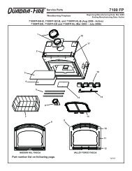
RRH. Igniter ReplacementIgniterBracketFigure 36.11. Turn down thermostat, let the appliance completelycool and then unplug appliance before servicing.2. Open the ash door and remove the ash pan. Removethe left side panel by loosening 2 screws (do notremove) and pull side panel away.3. The wire leads to the igniter are connected to thewire harness (black wires) with 1/4 inch male / femalespade connectors. Disconnect the spade connections.Loosen the thumb screw and slide igniter out.4. Install new igniter into the chamber and tighten thethumb screw.5. Re-connect the wires to the 2 leads with the spadeconnectors. Double check that the igniter wires areclear of any movement, i.e. ash pan, firepot cleaningrod, cleaning slide plates, etc.6. Re-install the ash pan, close the ash removal door.I. Glass ReplacementIgniterThumb ScrewWARNING• Glass is 5mm thick high temperature heatresistantceramic glass.• DO NOT REPLACE with any other material.• Alternate material may shatter and causeinjury1. Open the face and remove door from the applianceby lifting door off of hinge pin and lay on a flat surfaceface down.2. Using a screwdriver, tap the bottom of the rope retainerrod to push it up out of the hole. The top end of therod will slide up. Swing the rod toward you from thebottom and remove the rod. Repeat for other side.3. Remove old glass and replace with new glass.Figure 36.2Castile-B FS Pellet Stove4. Slide the retainer rod into the top hole first, and thenline up the bottom crimped end with the hole in thedoor. The crimped end must be parallel with the glassin order to insert it into place. Figure 36.2.GlassRope RetainerRodsJ. Damaged/Broken ComponentReplacementSlide topend in firstCrimped endat the bottomCrimped end must beparallel with the glass1. Replacement of broken or damaged componentsshould only be completed by a trained or qualifiedtechnician.2. In the event that you find a damaged component,please contact your local dealer, to send a servicetechnician to complete the removal and replacementof the parts.Castile-B FS Pellet Stove11Reference MaterialsWhen describing the location of a component,it is always AS YOU FACE THE FRONT OFTHE APPLIANCE.A. Component Function1. Control Boxa. The control box is located on upper right side ofappliance, behind the right side panel and above thevacuum switch.b. There is a light located inside of the control box. Theinternal light will turn green when the appliance hasreached a temperature of 175 o F (79°C) in the firepot.and will turn red when it reaches 600 o F (315°C).c. There is also an internal blue light located in the upperleft corner of the control box. When you plug in theappliance the blue light will automatically start blinking4 times in a row for 60 seconds and then will stop.NOTE:Do NOT open the control box. This will void thewarranty. FolIow proper shutdown procedures first ifyou need to plug in or remove the control box.2. Convection BlowerThe convection blower is mounted at the bottom rear of theappliance. There are 2 impellers, one on each side of themotor. The convection blower pushes heated air through theheat exchange system into the room.3. Combustion BlowerThe combustion blower is located on the right side ofappliance and is designed to pull the exhaust from theappliance and push it out through the venting system.4. Feed SystemThe feed system is located on the right side of the applianceand can be removed as an entire assembly. The assemblyincludes the feed motor, mounting bracket, bearing and feedspring (auger). The hollow feed spring (auger) pulls pelletsup the feed tube from the hopper area and drops them downthe feed chute into the firepot.5. FirepotThe firepot is made of high quality ductile iron and has acleaning pull-out rod. The floor of the firepot opens forcleaning when you pull out the rod. Be sure that the floorreturns to a completely closed position or your appliance willnot operate properly.6. FuseThe fuse is located on the front of the junction box on theright side of appliance. The fuse will blow should a shortoccur and shut off power to the appliance.7. Heat ExchangersThe heat exchangers transfer hot air from the exhaust systeminto convecton air. Remove the stainless steel top baffle toaccess the heat exchangers. There are 2 clean out rodslocated under the heat exchangers.8. Heat Output SwitchThe heat output switch is located on the upper right rearcorner. The funtion of the heat ouput switch is to regulatethe burn rates; low, medium and high settings.9. Hopper SwitchThe hopper switch is located in the upper right hand cornerof the hopper. This switch is designed to shut down the feedmotor whenever the hopper lid is opened.10. IgniterThe igniter is mounted on the base of the firepot. Combustionair travels over the red hot igniter creating super heated airthat ignites the pellets.11. Junction Box And Wiring HarnessThe junction box is located on the right side of the appliance,behind the right side panel. The junction box and wiringharness are replaced as one component.12. Power SupplyThe power outlet is located on the lower right side of theappliance on the front of the junction box. Check the wallreceptacle for 120 volt, 60 Hz (standard current). Make surethe outlet is grounded and has the correct polarity. A goodsurge protector is recommended. When operating with agenerator you need a least 600 watts of power, or with aninverter at least 800 watts of power available for the applianceduring the start cycle.13. Red Call LightThe red call light is on the front of the junction box, behindthe control box. The function of the red call light is to indicatethat the thermostat is calling for heat.14. Reset ButtonThe reset button is located on the back of the appliance onthe upper right corner of the side panel under the heat outputcontrol switch. The function of the button is to momentarilyopen the thermostat circuit, which restarts the system.15. ThermocoupleThe thermocouple is located on top of the firepot insidethe thermocouple cover (ceramic protection tube). Thethermocouple sends a millivolt signal to the control boxindicating the preset temperatures of the green and red lightshave been obtained.Page 36 7021-130D January 21, 2013January 21, 2013 7021-130D Page 37