GFK-160A Blower System - Heatilator Fireplaces
GFK-160A Blower System - Heatilator Fireplaces
GFK-160A Blower System - Heatilator Fireplaces

You also want an ePaper? Increase the reach of your titles
YUMPU automatically turns print PDFs into web optimized ePapers that Google loves.
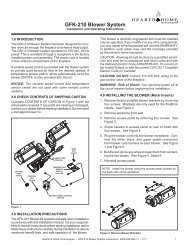
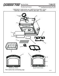
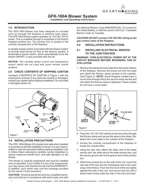
<strong>GFK</strong>-<strong>160A</strong> <strong>Blower</strong> <strong>System</strong>- Installation and Operating Instructions -1.0 INTRODUCTIONThe <strong>GFK</strong>-<strong>160A</strong> <strong>Blower</strong> has been designed to circulateroom air through the fi replace to enhance heat output.The <strong>GFK</strong><strong>160A</strong> blower system operates on 120 VAC, 60 Hzpower. This is available through a receptacle in the factoryinstalled junction box. The junction box is located in thecontrols compartment of the fi replace.A variable speed control is provided with the blower systemto provide quiet forced air fl ow at the desired speeds. Atemperature sensor switch, which automatically turns theblower ON/OFF, is also provided with this kit.NOTICE: The variable speed control and temperaturesensor swtich are not used with some remote controlsystems.2.0 CHECK CONTENTS OF SHIPPING CARTONCompare CONTENTS OF CARTON in Figure 1 with theactual parts received. If any parts are missing or damaged,contact your dealer before starting installation. Do not installa damaged blower kit.the National Electric Code ANSI/NFPA NO. 70-current (inthe United States), or with the current CSA C22.1 CanadianElectric Code (in Canada).CAUTION! DO NOT connect 110-120 VAC wiring to thegas control valve of the fireplace.4.0 INSTALLATION INSTRUCTIONS4.1 INSTALLING ELECTRICAL SERVICETO THE JUNCTION BOXWARNING: TURN ELECTRICAL POWER OFF AT THECIRCUIT BREAKER BEFORE BEGINNING THIS IN-STALLATION.1. Remove the electrical cover plate from the lower exteriorof the fi replace. Remove the knock-out from the plateand attach the Romex clamp (screws to the outside).(See Figure 2). NOTE: Some fi replace models have around hole through which the service wires are fed andinto which the Romex clamp is attached. These modelsdo not have a cover plate.BLOWERCONTROLKNOBCONTROLNUTWINGNUTTEMPERATURESENSORSWITCHLOWERGRILLECOVERPLATE110-120 VACFigure 2Figure 1SPEEDCONTROL3.0 INSTALLATION PRECAUTIONSThe <strong>GFK</strong>-<strong>160A</strong> <strong>Blower</strong> Kit is tested and safe when installedin accordance with this installation manual. It is your responsibilityto read all instructions before starting installation andto follow these instructions carefully during installation toassure maximum benefit from, and safe operation of, theblower.This blower is carefully engineered and must be installedonly as specifi ed. If you modify it or any of its components,you may cause a fire hazard and will void the WARRANTY.In addition, such action may void the coverage providedby the owner's home insurance.CAUTION: All wiring should be done by a qualified electricianand shall be in compliance with local codes and with2. Feed the 110-120 VAC electrical service wires throughthe Romex clamp and secure the wires to the clamp. Reattachthe cover plate to the outside of the fi replace.3. Access the controls compartment of the fi replace tolocate the Junction Box.4. Using the wire nuts, attach the black wire to the blackservice wire, the white wire to the white service wire, andthe service ground wire to the ground stud of the junctionbox.5. Attach the junction box to the side of the unit. Insert therear tab of the box into the rectangular slot in the outerwrap of the fi rebox. Push the front end of the box tightlyagainst the side of the unit, and secure the box with asheet metal screw (note the hole in the front end tab).1 Hearth & Home Technologies • <strong>GFK</strong>-<strong>160A</strong> <strong>Blower</strong> <strong>System</strong> Installation Instructions • 107-981 Rev P • 9/12
4.2 INSTALLING THE BLOWERPosition the blower all the way to the rear and centerin the fireplace. Pull the blower forward 1/8" to1/4" from the back wall of the fireplace (Figure 3).Thread blower cord plug through hole on bottom of cordbracket and plug into blower receptacle labeled "FAN" onpower cord.POWER CORD STYLE JUNCTION BOXPOWER CORD4.3 INSTALLING THE SPEED CONTROLAND SENSOR SWITCHIf using a remote control system that utilizes fancontrol, disregard steps 1-3 and follow remote controlinstallation instructions.1. Remove the knob and locknut from the variable speedcontrol. Slide the control behind the fi replace wall, inthe lower right front corner, with the stem sticking outof the pre-punched hole. Attach the locknut tightly andreattach the knob on the stem. Turn the speed controlswitch to the "ON" position.SENSOR SWITCHNOTE: Some models may have a separate mountinglocation on the base pan or valve bracket formounting this speed control.NOTE: SOME MODELS MAY HAVEA SEPARATE MOUNTING LOCATIONON THE BASE PANE OR VALVEBRACKET FOR MOUNTING THISSPEED CONTROL.BLOWERSPEED CONTROL2. Slide the temperature sensor switch/bracket assemblyonto the weld stud on the outside of the combustionchamber. Secure the bracket assembly with the wingnut provided. See Figure 4.NOTICE: The weld stud is located either on the lower rightside or the bottom of the combustion box.TEMPERATURESENSOR SWITCH1/8” TO 1/4”FIREPLACEWALLBLOWERSPEEDCONTROLWINGNUTPOWER STRIP STYLE JUNCTION BOXFigure 3BLOWERSENSORSWITCH“FAN”RECEPTACLESPEEDCONTROLFigure 4NOTICE: The switch/bracket assembly must be installedso that the sensor switch is facing the combustion boxsurface.3. Connect the variable speed control and the temperaturesensor switch to the junction box with the wires provided.See Figure 5 for the wiring diagram that matches thestyle of junction box on the fi replace.4. Turn the 110-120 VAC service "ON" at the circuitbreaker.2 Hearth & Home Technologies • <strong>GFK</strong>-<strong>160A</strong> <strong>Blower</strong> <strong>System</strong> Installation Instructions • 107-981 Rev P • 9/12
POWER CORD ASSEMBLYVARIABLE SPEED SWITCHPLUG INTO 120VEXISTING OUTLETWARNING! Risk of Shock! Replace damagedwire with type 105º C rated wire. Wire must havehigh temperature insulation.BLKBLKAUX / REMOTERECEPTACLEBLKBLKBLKBLOWERRECEPTACLETEMPERATURESENSOR SWITCHBLKPOWER STRIP STYLE JUNCTION BOXVARIABLESPEED SWITCHWARNING! Risk of Shock! Replace damagedwire with type 105º C rated wire. Wire must havehigh temperature insulation.JUNCTION BOXTEMPERATURESENSOR SWITCHBLUEFigure 5 Fan Wiring Diagram5.0 RECOMMENDED OPERATING PROCEDURESWHEN VARIABLE SPEED CONTROL ANDTEMPERATURE SWITCH ARE USEDIgnite the fire in the fireplace with the variable speed controlswitch in an "ON" position. The fan will automatically turnon when the temperature sensor switch closes at approximately110 O F. Heated air should be delivered at the outletgrille. The fan will continue to operate after the fi replace isturned OFF until the sensor switch opens.Various conditions (such as fi replace model, type of fi replaceinstallation, outside air temperature vs. inside airtemperature) can contribute to the length of the time theblower remains on after the fi replace is turned OFF. Theblower can be turned off manually with the speed controlswitch.WARNING! Risk of Injury! DO NOT contact blowerwheel (fan blades) during operation.6.0 MAINTENANCEPeriodically check the fi replace grilles and remove anydust, dirt or obstructions.7.0 REPLACEMENT PARTS AND CUSTOMERSERVICEReplacement parts and service may be obtained throughyour dealer.Hardware Bag: SRV107-570AAdapter with Ground: HTI-18-006Please contact your Hearth & Home Technologies dealerwith any questions or concerns.For the location of your nearestHearth & Home Technologies dealer,please visit www.fireside.com.Hearth & Home Technologies Inc.7571 215th Street West, Lakeville, MN 55044www.fi reside.com3 Hearth & Home Technologies • <strong>GFK</strong>-<strong>160A</strong> <strong>Blower</strong> <strong>System</strong> Installation Instructions • 107-981 Rev P • 9/12