GFK-210 Blower System - Heatilator Fireplaces
GFK-210 Blower System - Heatilator Fireplaces
GFK-210 Blower System - Heatilator Fireplaces

Create successful ePaper yourself
Turn your PDF publications into a flip-book with our unique Google optimized e-Paper software.
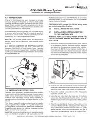
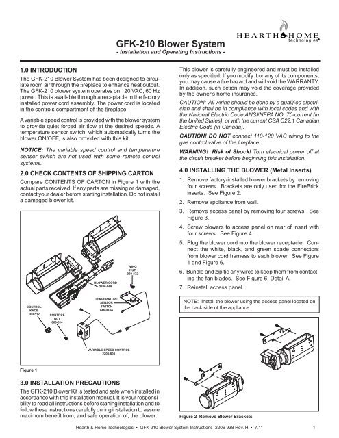
<strong>GFK</strong>-<strong>210</strong> <strong>Blower</strong> <strong>System</strong>- Installation and Operating Instructions -1.0 INTRODUCTIONThe <strong>GFK</strong>-<strong>210</strong> <strong>Blower</strong> <strong>System</strong> has been designed to circulateroom air through the fi replace to enhance heat output.The <strong>GFK</strong>-<strong>210</strong> blower system operates on 120 VAC, 60 Hzpower. This is available through a receptacle in the factoryinstalled power cord assembly. The power cord is locatedin the controls compartment of the fi replace.A variable speed control is provided with the blower systemto provide quiet forced air fl ow at the desired speeds. Atemperature sensor switch, which automatically turns theblower ON/OFF, is also provided with this kit.NOTICE: The variable speed control and temperaturesensor switch are not used with some remote controlsystems.2.0 CHECK CONTENTS OF SHIPPING CARTONCompare CONTENTS OF CARTON in Figure 1 with theactual parts received. If any parts are missing or damaged,contact your dealer before starting installation. Do not installa damaged blower kit.BLOWER CORD2206-068WINGNUT060-872This blower is carefully engineered and must be installedonly as specifi ed. If you modify it or any of its components,you may cause a fire hazard and will void the WARRANTY.In addition, such action may void the coverage providedby the owner's home insurance.CAUTION: All wiring should be done by a qualifi ed electricianand shall be in compliance with local codes and withthe National Electric Code ANSI/NFPA NO. 70-current (inthe United States), or with the current CSA C22.1 CanadianElectric Code (in Canada).CAUTION! DO NOT connect 110-120 VAC wiring to thegas control valve of the fi replace.WARNING! Risk of Shock! Turn electrical power off atthe circuit breaker before beginning this installation.4.0 INSTALLING THE BLOWER (Metal Inserts)1. Remove factory-installed blower brackets by removingfour screws. Brackets are only used for the FireBrickinserts. See Figure 2.2. Remove appliance from wall.3. Remove access panel by removing four screws. SeeFigure 3.4. Screw blowers to access panel on rear of insert withfour screws. See Figure 4.5. Plug the blower cord into the blower receptacle. Connectthe white, black, and green spade connectorsfrom blower cord harness to each blower. See Figure1 and Figure 6.6. Bundle and zip tie any wires to keep them from contactingthe fan blades. See Figure 6, Detail A.7. Reinstall access panel.CONTROLKNOB100-512CONTROLNUT060-814TEMPERATURESENSORSWITCH046-018ANOTE: Install the blower using the access panel located onthe back side of the appliance.VARIABLE SPEED CONTROL2206-800Figure 13.0 INSTALLATION PRECAUTIONSThe <strong>GFK</strong>-<strong>210</strong> <strong>Blower</strong> Kit is tested and safe when installed inaccordance with this installation manual. It is your responsibilityto read all instructions before starting installation and tofollow these instructions carefully during installation to assuremaximum benefit from, and safe operation of, the blower.Figure 2 Remove <strong>Blower</strong> BracketsHearth & Home Technologies • <strong>GFK</strong>-<strong>210</strong> <strong>Blower</strong> <strong>System</strong> Instructions 2206-938 Rev. H • 7/111
Figure 3 Remove Access CoverFigure 4 Attach <strong>Blower</strong>s to Access Cover2 Hearth & Home Technologies • <strong>GFK</strong>-<strong>210</strong> <strong>Blower</strong> <strong>System</strong> Instructions 2206-938 Rev. H • 7/11
5.0 INSTALLING THE VARIABLE SPEEDCONTROL AND TEMPERATURE SENSOR SWITCHIf using a remote control system that utilizes a blower(fan) control, disregard steps 1-3 and follow remote controlinstallation instructions.NOTICE! The sensor switch and rheostat are not usedif the blower is controlled with the RC300 remote control.1. Remove the knob and locknut from the variable speedcontrol. Slide the variable speed control behind thecontrol panel. With the stem sticking out of the prepunchedhole, attach the locknut tightly and reattachthe knob on the stem. See Figure 4. Turn the speedcontrol switch to the "ON" position.2. Slide the temperature sensor switch onto the blowerstud located on the bottom of the combustion box. SeeFigure 3. Secure the temperature sensor switch withthe wing nut provided.NOTICE: The blower stud is located on the bottom of thecombustion box. See Figure 5.NOTICE: The temperature sensor switch must be installedso that the sensor switch is facing the combustion boxsurface. See Detail A of Figure 5.3. Connect the variable speed control and the temperaturesensor switch to the power cord. See Figure 6.4. Gather the loose wires underneath the appliance anduse the zip ties to restrain them and keep them awayfrom the blower wheel (fan blades). See Figure 6,Detail A.5. Turn the 110-120 VAC service "ON" at the circuitbreaker.6.0 RECOMMENDED OPERATING PROCE-DURES WHEN VARIABLE SPEED CONTROL ANDTEMPERATURE SENSOR SWITCH ARE USEDIgnite the fire in the fireplace with the variable speed controlswitch in an "ON" position. The fan will automatically turnon when the temperature sensor switch closes at approximately110 O F. Heated air will be delivered at the outletgrille. The fan will continue to operate after the fi replaceis turned OFF until the temperature sensor switch opens.NOTICE! During operation, ensure that all wiring iskept away from the blower wheel (fan blades).Various conditions (such as fi replace model, type of fi replaceinstallation, outside air temperature vs. inside airtemperature) can contribute to the length of the time theblower remains on after the fi replace is turned OFF. Theblower can be turned off manually with the speed controlswitch.WARNING! Risk of Injury! DO NOT contact the blowerwheel (fan blades) during operation.7.0 MAINTENANCEPeriodically check the fi replace and remove any dust, dirtor obstructions.8.0 REPLACEMENT PARTS AND CUSTOMERSERVICEReplacement parts and service may be obtained throughyour dealer.Hardware Bag: SRV107-570AVARIABLESPEEDCONTROLTEMPERATURESENSORSWITCH BLOWERSTUDDETAIL ACOMBUSTION BOX SURFACEFigure 5BLOWER STUDTEMPERATURE SENSOR SWITCHHearth & Home Technologies • <strong>GFK</strong>-<strong>210</strong> <strong>Blower</strong> <strong>System</strong> Instructions 2206-938 Rev. H • 7/113
NOTE: IF ANY OF THE ORIGINALWIRE AS SUPPLIED WITH THEAPPLIANCE MUST BE REPLACED,IT MUST BE REPLACED WITHTYPE 105 0 C RATED WIRE.BLOWERDETAIL APOWER CORDPLUG120V EXISTINGOUTLETDETAIL ABRNBLACKREDBLOWERCORDTO VALVE BRACKET(GROUND)GRNTEMPERATURESENSORSWITCHORGTO VALVEVARIABLESPEEDCONTROL(RHEOSTAT)CONTROLPANELZIP TIESPLUG INTO 120VEXISTING OUTLETPOWERCORDVARIABLE SPEEDCONTROLDC REGULATORRECEPTACLEBLKBLKBLKWHTBLKTEMPERATURESENSOR SWITCHBLKBLOWERRECEPTACLEBLOWERCORDGRNBLKGRNBLKBLOWERSBLKBLKGRNWHTGRNBLKFigure 6. Fan Wiring Diagram - Metal Insert Without RC200/RC3004 Hearth & Home Technologies • <strong>GFK</strong>-<strong>210</strong> <strong>Blower</strong> <strong>System</strong> Instructions 2206-938 Rev. H • 7/11
9.0 Fan Wiring with RemoteThis appliance may be used with an RC200 or RC300remote control. See Figure 7.1. Remove cord assembly spades from rheostat andsensor switch.NOTICE: Fan speed and operation are controlled by theremote control. The sensor switch and rheostat are nolonger needed.2. Plug two cord assembly spade connectors together.3. Unplug fan cord assembly from standard cord assembly.4. Install fuse wire assembly in series between the blacklead wires of the fan cord and black lead wire on eachblower. See Figure 7.5. Plug fan cord assembly into AUX300 module.6. Plug AUX300 module into the standard cord assembly.NOTE: IF ANY OF THE ORIGINALWIRE AS SUPPLIED WITH THEAPPLIANCE MUST BE REPLACED,IT MUST BE REPLACED WITH TYPE105 0 C RATED WIRE.BLOWERPLUG120V EXISTINGOUTLETSTEP 5NOTE: USE ZIP TIES TO RESTRAINTHE LOOSE WIRES UNDERNEATHTHE APPLIANCE AND KEEP THEMAWAY FROM THE BLOWER WHEEL(FAN BLADES).STEPS3 & 5STEPS1 & 2SENSOR SWITCHWHT (2)GRN (2)BLK (2)BLK (2)GRN (2)BLK (2)SPEED CONTROL(RHEOSTAT)NOTE: SENSOR SWITCH ANDRHEOSTAT SPEED CONTROL MUSTBE REMOVED FROM CIRCUIT IFSYSTEM IS CONTROLLED WITHRC200/300 REMOTE.PLUG INTO 120VEXISTING OUTLETBLKBLKDC REGULATORRECEPTICLETO CONTROLMODULEBLOWERRECEPTICLEAUX 300 MODULEFANWHTGRNBLKBLKGRNWHTFUSE WIREASSEMBLYFUSE WIREASSEMBLYBLKGRNBLKBLKGRNBLKBLOWERSFigure 7. Fan Wiring Diagram - Metal Insert with RC200/RC300 RemoteHearth & Home Technologies • <strong>GFK</strong>-<strong>210</strong> <strong>Blower</strong> <strong>System</strong> Instructions 2206-938 Rev. H • 7/115
10.0 INSTALLING THE BLOWER (FireBrick Inserts)1. Remove appliance from wall.2. Disconnect power by shutting off circuit breaker orunplugging appliance power cord from its receptacle.3. Remove access panel from lower rear of the fi replaceinsert. See Figure 8.4. Attach blower to base with two screws. See Figure9. Connect white and green wires from blower wireassembly to each blower. See Figure 9. Connect thefuse wire assembly in series between black wires ofblower wire assembly and each blower. See Figure10.5. Insert plug from blower cable assembly into AUX300receptacle. See Figure 10.6. Bundle and zip tie loose wires to keep them from contactingblower impeller blades7. Position the right and left blower assembly into the rearopening. Take care to ensure that blower housing or itsmotor is clear of any adjacent metal. This will ensurethat no undue noise occurs during blower operation.8. Reinstall access panel.9. Reconnect power to the insert and install into wall.POWER CORDFigure 8. Remove Access PanelBLOWERACCESS PANELFigure 9. Attach <strong>Blower</strong> to Base6 Hearth & Home Technologies • <strong>GFK</strong>-<strong>210</strong> <strong>Blower</strong> <strong>System</strong> Instructions 2206-938 Rev. H • 7/11
Note: if any of the original wire assupplied with the appliance mustbe replaced, it must be replacedwith type 105 °C rated wire.Note: use zip ties to restrainthe loose wires underneath theappliance and keep them awayfrom the blower wheel (fan blades).BLOWERSPLUG TOEXISTINGOUTLETPLUG INTO 120VEXISTING OUTLETBROWNREDBLACKDC REGULATORRECEPTACLEBLKWHTGRNGROUND (TO VALVE BRACKET)GREEN (TO VALVE)ORANGE (TO VALVE)BLKGRNBLOWERRECEPTACLEBLKFUSE WIREASSEMBLYBLKBLOWERSBLKBLKFUSE WIREASSEMBLYBLKGRNGRNWHTBLKFigure 10. Fan Wiring Diagram - FireBrick InsertsPlease contact your Hearth & Home Technologies dealerwith any questions or concerns.For the location of your nearestHearth & Home Technologies dealer,please visit www.fireside.com.Hearth & Home Technologies Inc.7571 215th Street West, Lakeville, MN 55044www.fi reside.comHearth & Home Technologies • <strong>GFK</strong>-<strong>210</strong> <strong>Blower</strong> <strong>System</strong> Instructions 2206-938 Rev. H • 7/117