33734K- Imperial Gas Logs.indd - Hearth & Home Technologies
33734K- Imperial Gas Logs.indd - Hearth & Home Technologies
33734K- Imperial Gas Logs.indd - Hearth & Home Technologies

You also want an ePaper? Increase the reach of your titles
YUMPU automatically turns print PDFs into web optimized ePapers that Google loves.
These gas log sets are available with different valve systems. The Fi36S, Fi36SL, Fi42S and Fi42SL sets use a separateregulator and valve system, and the Fi36M, Fi36ML, Fi42M and Fi42ML sets use a combination control with an intermittentpilot. Both valve systems are available in natural or propane gas. Only the “M” Series can be used with an optionalremote control (RC-BATT-HTL).Conversion kits to convert from natural gas to propane or from propane to natural gas are available.• The conversion kits for all “M” series log sets are:- DCKP to convert from natural gas to propane- DCKN to convert from propane to natural gas.• The conversion kits for all “S” series log sets are:- CKMP to convert from natural to propane gas- CKMN to convert from propane to natural gas.These HEATILATOR® gas log sets and components have been tested and will operate safely when installed in accordancewith this installation manual. This decorative appliance is a highly engineered system. Unless you use HEATILA-TOR® components which have been designed for the system, you may create a fire hazard.Model No. BTU/Hr. Input OrificeFi36M.152Fi36ML .09360,000Fi36S .169Fi36SL .093Fi42M.182Fi42ML .11080,000Fi42S .228Fi42SL .110<strong>Gas</strong> PressureInlet gas supply pressure (NG) 4.5 (min) - 7.0 (max) in. w.c.Optimal manifold pressure (NG) 3.5 in. w.c.Inlet gas supply pressure (LP) 11.0 (min) - 14.0 (max) in. w.c.Optimum manifold pressure (LP) 10 in. w.c.<strong>Gas</strong> pressureBTU/hr. Input4 33734 Rev K 11/12
C. Important InformationInstaller: Please leave these instructions with the owner.Owner: Please retain these instructions for future reference.Important: Read these instructions carefully before making installation.• This appliance must be installed only in a solid-fuel burning (woodburning) fi replace with a working flue andconstructed of noncombustible materials.• The appliance area must be kept clear and free from combustible materials, gasoline and other fl ammablevapors and liquids.• A fi replace screen must be in place when the log set is burning and, unless other provisions for combustionair are provided, the screen shall have an opening(s) for introduction of combustion air.• Installation and the provisions for combustion and ventilation air must conform with the latest edition of theNational Fuel <strong>Gas</strong> Code ANSI Z223.1 or in Canada, the current CAN/CGA-B149.1 and B149.2.• Inlet and outlet taps are provided on the gas control (M Series) for a test gauge connection. Replace the plugafter the test.• The appliance and its manual shutoff valve must be disconnected from the gas supply piping system duringany pressure testing of that system at test pressures in excess of 1/2 PSIG.• The appliance must be isolated from the gas supply piping system by closing its individual manual shutoffvalve during any pressure testing of the gas supply pipe system at test pressure equal to or less than 1/2PSIG.• The minimum size fi replace in which the log set can be installed and the minimum permanent free openingthat must be provided by either the fireplace chimney or chimney damper to vent the fl ue gases must be inaccordance with the tables in Figure 1.• Any chimney damper must be fixed so that the minimum permanent vent opening will be maintained at alltimes (by screw, bolt at damper edge, or hole in damper.)• Solid fuel shall not be burned in a fi replace where a decorative gas appliance is installed.1. High Altitude InstallationFor U.S. installation, appliances are tested and approved for elevations from 0-2000 feet. When installing this <strong>Imperial</strong><strong>Gas</strong> Log Set at an elevation above 2000 feet, National Fuel <strong>Gas</strong> Codes require a decrease of the input rating by changingthe existing burner orifi ce to a smaller size. Input should be reduced 4% for each 1000 feet above sea level. Check withthe local gas utility for proper orifi ce size identifi cation. The current orifi ce is available from your Heatilator distributor.For Canada, appliances are certifi ed for elevations from 0-4500 feet. When installing this <strong>Imperial</strong> <strong>Gas</strong> Log Set at anelevation between 0-4500 feet in Canada, the input rating does not need to be reduced. When installing this log set at anelevation above 4500 feet in Canada, check with local authorities.2. Minimum DimensionsMinimum Firebox DimensionsMinimum Permanent Free OpeningSet Size Depth Height Front Opening Chimney Ht. (ft) 36 in. 42 in.36 in. 13 in. 16 in. 30 in. 10 ft 40 sq in. 40 sq in.42 in. 13 in. 16 in. 34 in.Figure 111/12 33734 Rev K 5
D. Step-by-Step Installation1. Unpack the Log SetCarefully remove all parts from the shipping container.Your set includes four fi ber logs, a burner assembly, thegrate assembly, fi re embers, lava rock, damper stop, and10” fl ex connector.2. Install the Damper StopTo install the damper stop: Open the damper to the fullyopen position and secure it open with the stop as shown inFigure 2.b. Remove the four screws that secure the top pan tothe base of the appliance. See Figure 4.Figure 4 - Top Panc. Set the burner assembly and top pan aside.d. The gas line connection for the <strong>Imperial</strong> Series <strong>Gas</strong>Log Set may be plumbed from either the right orleft side of the appliance.Figure 2 - Damper OperationIf the damper stop doesn’t fi t your application, use a permanentmeans that will keep the damper open at least tothe minimum vent opening. See Figure 1.3. Position the Log Set in the FireplaceThe burner assembly should be located as far back aspossible and centered left to right in the combustion chamberof the vented fireplace.4. Connect the <strong>Gas</strong> LineThe appliance is provided with a stainless steel fl exibleconnector and a listed (and Commonwealth of Massachusettsapproved) T-handle manual shutoff valve.a. Remove the four screws that secure the burnerassembly to the top pan. See Figure 3.Note: One manual shutoff valve is supplied withthe appliance. This appliance must be installedwith an additional manual shutoff valve (notsupplied) located no more than six feet from theappliance.e. The 1/2” iron pipe incoming gas line should be pipedinto the valve compartment from either the right orleft side and connected to the brass flare connectorand the 10” stainless steel fl ex line (supplied). SeeFigure 5.Optional: Seal around the gas line to prevent coldair leakage.Figure 3 - Burner AssemblyFigure 5 - <strong>Gas</strong> Line ConnectionNote: Have the gas supply line installed in accordance with building codes by a qualifi ed installer approved and/orlicensed as required by the locality. In the Commonwealth of Massachusetts, installation must be performed by a licensedplumber or gas fi tter.6 33734 Rev K 11/12
f. Bleed the gas line to extract any air that may havebeen trapped inside the pipe. All connectionsmust be tightened and checked for leaks with acommercially available, non-corrosive leak checksolution. Be sure to rinse off the solution when doneleak testing. DO NOT USE AN OPEN FLAME. Turnoff the gas after the leak test.g. Reassemble the top pan with the four screwsremoved earlier, and the burner assembly with thefour screws removed earlier.Note: Be sure when reassembling the burnerassembly that the burner neck is properly positionedon the orifi ce.5. Grate AssemblyThe grate assembly should be positioned on top of the toppan and the burner assemblies, centered from left to rightand pulled forward as far as possible. See Figure 6.Figure 7 - Rock Wool Placementc. Lava RockPlace on the hearth refractory of the fi replace, all aroundthe log set. See Figure 8.Figure 8 - Lava RockFigure 6 - Placing the Grate Assembly6. Place the Rock Wool, Fire Glow, LavaRock and Vermiculitea. Rock WoolPlace approximately 1/2” diameter pieces of rockwool on the top of the burner covering the front 2/3of the burner. Do not cover the rear row of burnerports. The rock wool should also be placed to thesides of the burner on the top pan and under thefront bar of the grate assembly to hide the burner.See Figure 7.b. Fire Glow (Fire 98)A fl ame colorant material that also adds to therealism of the gas appliance fl ame. After placingthe rock wool, sprinkle some of the Fire Glow onthe top of the burner assembly and the rock wool.d. VermiculiteWhen placing the vermiculite, sprinkle it evenly overthe area covered by the lava rock.e. It is not necessary to use the entire bag of the rockwool, the Fire Glow, the lava rock or the vermiculite.Save the remaining portions for later use.11/12 33734 Rev K 7
7. Place the <strong>Logs</strong>a. Rear LogThe rear log is supplied with locating slots in thebase of the log. Locate the rear log over the locatingtabs at the rear of the top pan. See Figure 9.c. Top Right LogThe top right log is supplied with locating slots inthe base of the log. Locate the log over the twolocating pins found in the rear log and the front log.See Figure 11.Figure 9 - Rear Log PlacementFigure 11 - Top Right Logb. Front LogThe front log is supplied with notches in the baseof the log to locate the log on the grate. Line upthe notches in the log with the grate bars and pullthe log forward until it comes into contact with theupright portion of the grate bars. See Figure 10.d. Top Left LogThe top left log is supplied with a locating tab thatfi ts into a notch on the top of the front log. SeeFigure 12.Figure 10 - Placing the Front LogFigure 12 - Top Left Log8 33734 Rev K 11/12
8. Intermittent Pilot Ignitiona. Appliance Requirements: This appliance does not require 110VAC supply for operation.1) A wiring diagram is shown in Figure 13. A battery pack is supplied with the appliance. This appliancerequires the use of two D-cell batteries (not supplied with the appliance) for operation.2) In the event of a power outage, the appliance will continue to operate if batteries are installed in the batterypack.Figure 13 - “M” Series Intermittent Pilot Wiring Diagramb. Battery Replacement1) Access Cover - Remove the access cover by locating the two hand tabs on either side of the access cover.Slide the access cover to the right approximately 1” to disengage it from the base. See Figure 14.2) Battery Pack - Locate the battery pack and slide it forward out of the base. See Figure 15. Replace batteriesand reinstall the battery pack into the base. The battery pack is held in place by a magnet located on thebase pan.ON/OFF SwitchFigure 14 - Access Cover RemovalFigure 15 - Battery Replacement11/12 33734 Rev K 9
E. Operating Instructions for the “M” SeriesFOR YOUR SAFETY READ BEFORE LIGHTINGWARNING: If you do not follow these instructions exactly, a fire or explosionmay result causing property damage, personal injury or loss of life.A. This appliance has an intermittent pilot. Whenlighting the pilot, follow these instructionsexactly.B. BEFORE LIGHTING smell all around theappliance area for gas. Be sure to smell next tothe floor because some gas is heavier than airand will settle to the floor.WHAT TO DO IF YOU SMELL GAS• Do not try to light any appliance.• Do not touch any electric switch; do not useany phone in your building.• Immediately call your gas supplier?from aneighbor's phone. Follow the gas supplier'sinstructions.• If you cannot reach your gas supplier, callthe fire department.C. Do not use this appliance if any part has beenunder water. Immediately call a qualified servicetechnician to inspect the appliance and toreplace any part of the control system and anygas control which has been under water.Due to high surface termperatures, keep children, clothing and furniture away.Keep burner and control compartment clean. See installation and operating instructions accompanying the appliance.FOR YOUR SAFETY: Do not store or use gasoline or other flammable vapors and liquids in the vicinity of thisor any other appliance.Lighting Instructions, “M” SeriesLIGHTING INSTRUCTIONS1. STOP! Read the safety instruction label.2. Turn wall switch to the "OFF" position.5. To light pilot and main burner, turn wall switch to "ON".Do not light by hand.6. If appliance will not operate, follow the instructions "TOTURN OFF GAS TO APPLIANCE" and call your servicetechnician or gas supplier.GASCONTROLKNOB3. Wait five minutes to clear out any gas. If you smellgas, STOP! Follow "B" on the safety informationlabel. If you don't smell gas, go to next step.4. Locate pilot assembly inside unit.PILOTBURNERFLAMESENSORIGNITOR1. Turn on/off switch to "OFF".TO TURN OFF GAS APPLIANCE3400610 33734 Rev K 11/12
F. Operating Instructions for the “S” SeriesFOR YOUR SAFETY READ BEFORE LIGHTINGWARNING: If you do not follow these instructions exactly, a fire or explosion mayresult causing property damage, personal injury or loss of life.A. This appliance has a pilot which must be lit byhand. When lighting the pilot, follow theseinstructions exactly.B. BEFORE LIGHTING smell all around theappliance area for gas. Be sure to smell next tothe floor because some gas is heavier than airand will settle to the floor.WHAT TO DO IF YOU SMELL GAS• Do not try to light any appliance.• Do not touch any electric switch; do not useany phone in your building.• Immediately call your gas supplier?from aneighbor's phone. Follow the gas supplier'sinstructions.• If you cannot reach your gas supplier, callthe fire department.C. Use only your hand to push in or turn the gas controlknob. Never use tools. If the knob will not push in orturn by hand, don't try to repair it, call a qualifiedservice technician. Force or attempted repair mayresult in a fire or explosion.D. Do not use this appliance if any part has been underwater. Immediately call a qualified service technicianto inspect the appliance and to replace anypart of the control system and any gas controlwhich has been under water.Due to high surface termperatures, keep children, clothing and furniture away.Keep burner and control compartment clean. See installation and operating instructions accompanying the appliance.FOR YOUR SAFETY: Do not store or use gasoline or other flammable vapors and liquids in the vicinity ofthis or any other appliance.Lighting Instructions for the “S” Series3. Wait five minutes to clear out any gas. If you smellgas, STOP! Follow "B" on the safety informationlabel. If you don't smell gas, go to next step.4. Find pilot--follow metal tube from gas control. Thepilot is behind the burner pan.LIGHTING INSTRUCTIONS1. STOP! Read the safety instruction label. 5. Turn knob on control counterclockwise to "PILOT".2. Turn gas control knob clockwise to "OFF". 6. Push in the knob all the way and hold in. Immediatelylight the pilot with the use of a paper match and lighterrod. Continue to hold the control knob in for about oneminute after the pilot is lit. Release button and it will popback up. Pilot should remain lit. If it goes out, repeatsteps 3 through 7.If button does not pop up when released, stop andimmediately call your service technician or gas supplier.If the pilot will not stay lit after several tries, turn the gascontrol knob to "OFF" and call your service technicianor gas supplier.7. Turn gas control knob counterclockwise to "ON".Knob can be turned to "ON" only if the control knob ispopped out.THERMOCOUPLEPILOTBURNERTO TURN OFF GAS APPLIANCE1. Turn gas control clockwise to "OFF. Do not force.3400811/12 33734 Rev K 11
G. Glass DoorsIf your fi replace is equipped with a glass door, the glass doors should be in the full open position when the appliance isoperating. Operating the fi replace with the glass doors closed will block the radiant heat output of the fireplace and maycause incomplete combustion of the natural or propane gas fuel.IMPORTANT! Always ensure that the wire fi replace screen is closed when the fi replace is operating.H. CleaningYour gas logs require little care. Keep the burner assembly, logs and burner area surrounding the logs clean by vacuumingor brushing with a dry paint brush at least twice a year.CAUTION:The logs can get very hot. Handle only when theyare cool.CAUTION:After burning, the log becomes fragile, so take carein handling.• Always turn off the gas to the pilot before cleaning. For relighting, refer to lighting instructions located onpages 10 and 11.• Always keep the appliance clear and free from combustible materials, gasoline, and other fl ammable vaporsand liquids.• Never obstruct the fl ow of combustion and ventilation air. Keep the front of the appliance clear of all obstaclesand materials.• Leave clearance of at least 36” from the front of the fi replace.• The air shutter should not be blocked.I. Inspecting the Venting SystemThe fi replace venting system is designed and constructed to develop a positive fl ow adequate to remove flue gases to theoutside atmosphere. See vented fi replace installation instructions.1. A spillage test must be made before the installed appliance is left with the consumer.a. Close all doors and windows in the home.b. Light the log set.c. After three minutes, test with a smoke match, smoke candle, stick incense, or cigarette 1” below the topof the opening (lintel) moving across the full width. See Figure 16. If spillage (smoke drawn into the room)occurs, it will most likely be near the top, outside corners.Figure 16 - Checking for Spillage12 33734 Rev K 11/12
2. Possible Curesa. The damper needs to be opened further.b. The fireplace opening needs to be reduced by adding a drop panel across the top under the lintel.c. The air supply from outdoors needs to be increased. Open the outside air kit if the fi replace is so equipped,or crack open a door or window.d. If necessary, seek expert advice. Do not operate this appliance.3. CleaningPeriodic examination and cleaning of the venting system of the solid-fuel burning fireplace should be done before initialuse and at least annually by a qualifi ed agency.J. Important Safeguards1. Other Fuelsa. Although your gas log set is very realistic in appearance, it is not a real woodburning fi re and must not beused for burning any fuel other than natural or propane gas.b. To avoid irreparable damage to the appliance and/or personal injury, wood, matches, paper, garbage or anyother material must not be placed or thrown on top of the logs.2. Fireplace Safetya. To avoid personal injury, do not touch hot surfaces when the appliance is operating.b. Always ensure that the fi replace screen is closed when the appliance is operating.c. Close supervision is necessary when the appliance is being used near children.K. Servicing• Repair and replacement work should be done by a qualified service technician.• Always shut off the gas supply and make sure the appliance is cool before beginning any serviceoperation.• Always check for gas leaks after servicing.• Always check for proper venting.L. Owner Registration/WarrantyPlease complete and return your owner registration card to ensure proper warranty coverage. If you wish to communicatewith the factory, write to Heatilator Technical Services Dept., <strong>Hearth</strong> & <strong>Home</strong> <strong>Technologies</strong> Inc., 1915 W. Saunders Street,Mt. Pleasant, Iowa 52641M. Replacement PartsParts lists with exploded views follow. Always include correct name, part number and model number of the appliancewhen ordering replacement parts. Contact your local dealer to order parts.11/12 33734 Rev K 13
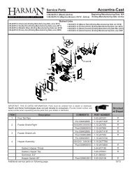
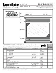
Service Parts<strong>Imperial</strong> 36” <strong>Gas</strong> Log SetFI36M, FI36MLBeginning Manufacturing Date: N/AEnding Manufacturing Date: ActiveLog Set Assembly423156789101112 131415171618Part number list on following page.11/1214 33734 Rev K 11/12
Service PartsFI36M, FI36MLBeginning Manufacturing Date: N/AEnding Manufacturing Date: ActiveIMPORTANT: THIS IS DATED INFORMATION. When requesting service or replacementparts for your appliance please provide model number and serial number. All parts listedin this manual may be ordered from an authorized dealer.Stockedat DepotITEM DESCRIPTION COMMENTS PART NUMBER1 Back Log SRV322332 Front Log SRV322343 Top Right Log SRV337324 Top Left Log SRV337335 Grate Assembly 337436 Burner Assembly 33725 Y7 Control Module 593-592 Y8 Brass Connector 303-315/5 Y9Valve NG 593-500 YValve LP 593-501 Y10 Brass Male Connector 1342511 <strong>Gas</strong> Tube 3372912Orifi ce NG (.152) 32229 YOrifi ce LP (.093) 16752 Y13 Bulkhead 13405A14Pilot Assembly NG 385-510A YPilot Assembly LP 385-511A Y15 Pilot Bracket 3337516 Battery Pack 593-594A Y17 ON/OFF Rocker Switch 060-51118 Access Cover 32238Damper Stop Assembly 14354 Y10 in. Flexline 15696B YDexen Wire Harness 593-590A YWool, Rock, Vermiculite 34010Lava Rock (2lb. Bag) 4021-296Mineral Wool14333BVermiculite 28746"Z" Bracket 32228Wire Harness Qty 2 req 33995Conversion Kit NG DCKN YConversion Kit LP DCKP YPilot Orifi ce NG, .021 446-505 YPilot Orifi ce LP, .011 446-517 YRegulator NG NGK-DXF YRegulator LP LPK-DXF YInstallation Manual 3373415 33734 Rev K 11/12
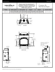
Service Parts<strong>Imperial</strong> 36” <strong>Gas</strong> Log setFI36S, FI36SLBeginning Manufacturing Date: Nov 2000Ending Manufacturing Date: Nov 20065Log Set Assembly6423197816151011 12 1314IMPORTANT: THIS IS DATED INFORMATION. When requesting service or replacement parts foryour appliance please provide model number and serial number. All parts listed in this manual maybe ordered from an authorized dealer.ITEM DESCRIPTION COMMENTS PART NUMBER1 Back Log SRV322332 Front Log SRV322343 Top Right Log SRV337324 Top Left Log SRV337335 Grate Assembly 33743Stockedat Depot6 Burner Assembly 33725 Y7Pilot Assembly NG 33993 YPilot Assembly LP 33994 Y8 Pilot Bracket No longer available 337359 <strong>Gas</strong> Tube No longer available 3398910 Brass Male Connector 1342511 Valve 33992 Y12 Pipe Nipple 4021-04113 Regulator 3402814Orifi ce NG (.169) 18742Orifi ce LP (.093) 16752 Y15 Brass Bulkhead 13405A Y16 Brass Connector - 90 degree - Flex 4021-045Brass Connector Pkg of 5 303-315/5 YDamper Stop Assembly 14354 Y10 in. Flexline 15696B YWool, Rock, Vermiculite 34010Lava Rock (2lb. Bag) 4021-296Mineral Wool14333BVermiculite 28746Conversion Kit NG No longer available CKMNConversion Kit LP No longer available CKMP10/1216 33734 Rev K 11/12
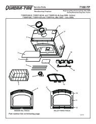
Service Parts<strong>Imperial</strong> 42” <strong>Gas</strong> Log setFI42M, FI42MLBeginning Manufacturing Date: N/AEnding Manufacturing Date: ActiveLog Set Assembly423156789101112 131415171618Part number list on following page.11/1217 33734 Rev K 11/12
Service PartsFI42M, FI42MLBeginning Manufacturing Date: N/AEnding Manufacturing Date: ActiveIMPORTANT: THIS IS DATED INFORMATION. When requesting service or replacementparts for your appliance please provide model number and serial number. All parts listedin this manual may be ordered from an authorized dealer.Stockedat DepotITEM DESCRIPTION COMMENTS PART NUMBER1 Back Log SRV322332 Front Log SRV322343 Top Right Log SRV337324 Top Left Log SRV337335 Grate Assembly 337436 Burner Assembly 33725 Y7 Control Module 593-592 Y8 Brass Connector Pkg of 5 303-315/5 Y9Valve NG 593-500 YValve LP 593-501 Y10 Brass Male Connector 1342511 <strong>Gas</strong> Tube 3372912Orifi ce NG (.182) 32230Orifi ce LP (.110) 17235 Y13 Bulkhead 13405A14Pilot Assembly NG 385-510A YPilot Assembly LP 385-511A Y15 Pilot Bracket 3337516 Battery Pack 593-594A Y17 ON/OFF Rocker Switch 060-511 Y18 Access Cover 32238Damper Stop Assembly 14354 Y10 in. Flexline 15696B YDexen Wire Harness 593-590A YWool, Rock, Vermiculite 34010Lava Rock (2lb. Bag) 4021-296Mineral Wool14333BVermiculite 28746"Z" Bracket 32228Wire Harness Qty 2 req 33995Conversion Kit NG DCKN YConversion Kit LP DCKP YPilot Orifi ce NG, .021 446-505 YPilot Orifi ce LP, .011 446-517 YRegulator NG NGK-DXF YRegulator LP LPK-DXF YInstallation Manual 3373411/12 33734 Rev K 18
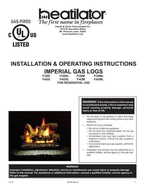
11 12 1314Service Parts<strong>Imperial</strong> 42”<strong>Gas</strong> Log setFI42S, FI42SLBeginning Manufacturing Date: Nov 2000Ending Manufacturing Date: Nov 2006Log Set Assembly564231789101615IMPORTANT: THIS IS DATED INFORMATION. When requesting service or replacement parts foryour appliance please provide model number and serial number. All parts listed in this manual maybe ordered from an authorized dealer.ITEM DESCRIPTION COMMENTS PART NUMBER1 Back Log SRV322332 Front Log SRV322343 Top Right Log SRV337324 Top Left Log SRV337335 Grate Assembly 33743Stockedat Depot6 Burner Assembly 33725 Y7Pilot Assembly NG 33993 YPilot Assembly LP 33994 Y8 Pilot Bracket No longer available 337359 <strong>Gas</strong> Tube No longer available 3398910 Brass Male Connector 1342511 Valve 33992 Y12 Pipe Nipple 4021-04113 Regulator 3402814Orifi ce NG (.228) 33736Orifi ce LP (.110) 17235 Y15 Brass Bulkhead 13405A Y16 Brass Connector - 90 degree - Flex 4021-045Brass Connector Pkg of 5 303-315/5 YDamper Stop Assembly 14354 Y10 in. Flexline 15696B YWool, Rock, Vermiculite 34010Lava Rock (2lb. Bag) 4021-296Mineral Wool14333BVermiculite 28746Conversion Kit NG No longer available CKMNConversion Kit LP No longer available CKMP19 33734 Rev K 11/122/12
N. Troubleshooting - “M” SeriesWith proper installation and maintenance, your new decorative gas appliance should provide years of trouble-free service.If you do experience a problem, refer to the troubleshooting guide below. This guide will assist you or a qualified servicetechnician in the diagnosis of problems and the corrective action to be taken.Symptoms Possible Causes Corrective Action1 Pilot sparks, but will not lightafter repeated attempts.a. Main gas shutoff valve closed. Make sure that the shutoff valve located on theincoming gas line is open.b. Air in the gas line. Bleed air out of the gas line. Retest for gas leaksafter bleeding.c. Pilot orifi ce is plugged, notallowing gas to fl ow.This repair requires tools and some degree ofexperience. Call a qualifi ed service technician.d. Misaligned electrode. Check spark gap; spark should be extendingapproximately 1/8” to the pilot hood. Adjust gap togive proper spark. Remove hands from electrodebefore attempting to spark.e. No gas supply to the appliance. Check plumbing to ensure the appliance has beenhooked up to the gas supply line.The propane tank is empty.f. Ground wire loose. Check that the black ground wire from the ignitioncontrol box is securely attached to the ground.g. Weak batteries. Replace with two new “D” sized batteries.2 Pilot lights, but will not stay lit. a. Weak pilot fl ame. Pilot fl ame must engulf the fl ame sensor. Clean and/or adjust pilot for maximum fl ame impingement onfl ame sensor.b. Loose wire connection Check for loose wires from the pilot to the ignitioncontrol box.c. Faulty fl ame sensor. Check the wire connection into the ignition controlbox. If the connection is correct, replace sensor.3 Pilot does not spark at all. a. Loose wire connection. Check for loose wires from On/Off switch to ignitioncontrol and remote control.b. Remote control. Make sure the switch located on the front of theremote control is set to the “Remote” setting.c. Weak batteries. Replace with two new “D” sized batteries.20 33734 Rev K 11/12
O. TROUBLESHOOTING - “S” SERIESSymptoms Possible Causes Corrective Action1 Match will not light pilot. a. Main gas shutoff valve closed. Make sure that the shutoff valve located on theincoming gas line is open.b. Air in the gas line. Light a match. Turn valve knob to “PILOT” positionand depress. Keep match near pilot burner until itlights.2 Pilot lights, but will not stay litafter carefully following lightinginstructions.c. Valve knob is in “OFF” position Turn valve knob to “PILOT” position and depress.Keep match near pilot burner until it lights.d. Pilot orifi ce is plugged, notallowing gas to flowThis repair requires tools and some degree ofexperience. Call a qualifi ed service technician.e. No gas supply to the appliance. Check the plumbing to ensure the appliance hasbeen hooked up to the gas supply line.a. Thermocouple too tight or tooloose.Thermocouple must be attached to the valve fi ngertight,plus a 1/8 turn with a wrench.b. Weak pilot fl ame. Pilot fl ame must engulf the thermocouple. Cleanand/or adjust pilot for maximum fl ame impingementon the thermocouple.c. Defective thermocouple. Check the thermocouple with a millivolt meter asfollows: Disconnect the thermocouple from thevalve and connect the red lead of the meter to thesilver end of the thermocouple. Now connect theblack lead of the meter to the copper tubing of thethermocouple. Light the pilot and keep the knobdepressed while taking readings. The meter readingsshould be greater than 14 mV. If not, replacethermocouple.3 Pilot “ON”. No gas to mainburner, valve knob “ON”.a. A blockage is preventing gasfl ow.Inspect the burner orifi ce for obstruction. Call aqualifi ed service technician.b. Defective valve. Replace gas valve. Call a qualifi ed servicetechnician.11/12 33734 Rev K 21
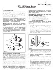
P. Accessory Parts (For “M” Series Only)The following accessory parts can be obtained from your dealer. The wireless remote control switch is suppliedwith installation instructions packaged with them. Should you need additional information please contact yourdealer for more information or visit: www.hpba.org/staysafe.Remote ControlRC-BATT-HTL22 33734 Rev K 11/12
<strong>Hearth</strong> & <strong>Home</strong> <strong>Technologies</strong> Inc.LIMITED LIFETIME WARRANTY<strong>Hearth</strong> & <strong>Home</strong> <strong>Technologies</strong> Inc., on behalf of its hearth brands (”HHT”), extends the following warranty forHHT gas, wood, pellet, coal and electric hearth appliances that are purchased from an HHT authorized dealer.WARRANTY COVERAGE:HHT warrants to the original owner of the HHT appliance at the site of installation, and to any transferee taking ownershipof the appliance at the site of installation within two years following the date of original purchase, that the HHT appliancewill be free from defects in materials and workmanship at the time of manufacture. After installation, if covered componentsmanufactured by HHT are found to be defective in materials or workmanship during the applicable warranty period,HHT will, at its option, repair or replace the covered components. HHT, at its own discretion, may fully discharge all of itsobligations under such warranties by replacing the product itself or refunding the verified purchase price of the productitself. The maximum amount recoverable under this warranty is limited to the purchase price of the product. This warrantyis subject to conditions, exclusions and limitations as described below.WARRANTY PERIOD:Warranty coverage begins on the date of original purchase. In the case of new home construction, warranty coveragebegins on the date of first occupancy of the dwelling or six months after the sale of the product by an independent,authorized HHT dealer/ distributor, whichever occurs earlier. The warranty shall commence no later than 24 monthsfollowing the date of product shipment from HHT, regardless of the installation or occupancy date. The warranty period forparts and labor for covered components is produced in the following table.The term “Limited Lifetime” in the table below is defined as: 20 years from the beginning date of warranty coverage forgas appliances, and 10 years from the beginning date of warranty coverage for wood, pellet, and coal appliances. Thesetime periods reflect the minimum expected useful lives of the designated components under normal operating conditions.Warranty Period HHT Manufactured Appliances and VentingEPAParts Labor <strong>Gas</strong> Wood PelletCoal Electric VentingWoodComponents Covered1 YearX X X X X X XAll parts and material except ascovered by Conditions,Exclusions, and Limitationslisted2 yearsX X XIgniters, electronic components,and glassX X X X X Factory-installed blowersXMolded refractory panels3 yearsXFirepots and burnpots5 years 1 year X X Castings and baffles7 years 3 years X X XManifold tubes,HHT chimney and termination10yearsLimitedLifetime1 year X Burners, logs and refractory3 years X X X X X Firebox and heat exchanger90 DaysX X X X X X XSee conditions, exclusions, and limitations on next page.All replacement partsbeyond warranty period4021-645C 12-29-10 Page 1 of 211/12 33734 Rev K 23
WARRANTY CONDITIONS:• This warranty only covers HHT appliances that are purchased through an HHT authorized dealer or distributor. A list ofHHT authorized dealers is available on the HHT branded websites.• This warranty is only valid while the HHT appliance remains at the site of original installation.• Contact your installing dealer for warranty service. If the installing dealer is unable to provide necessary parts, contactthe nearest HHT authorized dealer or supplier. Additional service fees may apply if you are seeking warranty servicefrom a dealer other than the dealer from whom you originally purchased the product.• Check with your dealer in advance for any costs to you when arranging a warranty call. Travel and shipping chargesfor parts are not covered by this warranty.WARRANTY EXCLUSIONS:This warranty does not cover the following:• Changes in surface finishes as a result of normal use. As a heating appliance, some changes in color of interior andexterior surface finishes may occur. This is not a flaw and is not covered under warranty.• Damage to printed, plated, or enameled surfaces caused by fingerprints, accidents, misuse, scratches, melted items,or other external sources and residues left on the plated surfaces from the use of abrasive cleaners or polishes.• Repair or replacement of parts that are subject to normal wear and tear during the warranty period. These partsinclude: paint, wood, pellet and coal gaskets, firebricks, grates, flame guides, light bulbs, batteries and the discolorationof glass.• Minor expansion, contraction, or movement of certain parts causing noise. These conditions are normal and complaintsrelated to this noise are not covered by this warranty.• Damages resulting from: (1) failure to install, operate, or maintain the appliance in accordance with the installationinstructions, operating instructions, and listing agent identification label furnished with the appliance; (2) failure toinstall the appliance in accordance with local building codes; (3) shipping or improper handling; (4) improper operation,abuse, misuse, continued operation with damaged, corroded or failed components, accident, or improperly/incorrectly performed repairs; (5) environmental conditions, inadequate ventilation, negative pressure, or draftingcaused by tightly sealed constructions, insufficient make-up air supply, or handling devices such as exhaust fans orforced air furnaces or other such causes; (6) use of fuels other than those specified in the operating instructions; (7)installation or use of components not supplied with the appliance or any other components not expressly authorizedand approved by HHT; (8) modification of the appliance not expressly authorized and approved by HHT in writing;and/or (9) interruptions or fluctuations of electrical power supply to the appliance.• Non-HHT venting components, hearth components or other accessories used in conjunction with the appliance.• Any part of a pre-existing fireplace system in which an insert or a decorative gas appliance is installed.• HHT’s obligation under this warranty does not extend to the appliance’s capability to heat the desired space. Informationis provided to assist the consumer and the dealer in selecting the proper appliance for the application. Considerationmust be given to appliance location and configuration, environmental conditions, insulation and air tightness ofthe structure.This warranty is void if:• The appliance has been over-fired or operated in atmospheres contaminated by chlorine, fluorine, or other damagingchemicals. Over-firing can be identified by, but not limited to, warped plates or tubes, rust colored cast iron, bubbling,cracking and discoloration of steel or enamel finishes.• The appliance is subjected to prolonged periods of dampness or condensation.• There is any damage to the appliance or other components due to water or weather damage which is the result of, butnot limited to, improper chimney or venting installation.LIMITATIONS OF LIABILITY:• The owner’s exclusive remedy and HHT’s sole obligation under this warranty, under any other warranty, express orimplied, or in contract, tort or otherwise, shall be limited to replacement, repair, or refund, as specified above. In noevent will HHT be liable for any incidental or consequential damages caused by defects in the appliance. Some statesdo not allow exclusions or limitation of incidental or consequential damages, so these limitations may not apply to you.This warranty gives you specific rights; you may also have other rights, which vary from state to state. EXCEPT TOTHE EXTENT PROVIDED BY LAW, HHT MAKES NO EXPRESS WARRANTIES OTHER THAN THE WARRANTYSPECIFIED HEREIN. THE DURATION OF ANY IMPLIED WARRANTY IS LIMITED TO DURATION OF THEEXPRESSED WARRANTY SPECIFIED ABOVE.4021-645C 12-29-10 Page 2 of 224 33734 Rev K 11/12