33734K- Imperial Gas Logs.indd - Hearth & Home Technologies
33734K- Imperial Gas Logs.indd - Hearth & Home Technologies
33734K- Imperial Gas Logs.indd - Hearth & Home Technologies

Create successful ePaper yourself
Turn your PDF publications into a flip-book with our unique Google optimized e-Paper software.
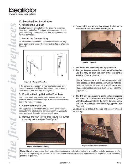
D. Step-by-Step Installation1. Unpack the Log SetCarefully remove all parts from the shipping container.Your set includes four fi ber logs, a burner assembly, thegrate assembly, fi re embers, lava rock, damper stop, and10” fl ex connector.2. Install the Damper StopTo install the damper stop: Open the damper to the fullyopen position and secure it open with the stop as shown inFigure 2.b. Remove the four screws that secure the top pan tothe base of the appliance. See Figure 4.Figure 4 - Top Panc. Set the burner assembly and top pan aside.d. The gas line connection for the <strong>Imperial</strong> Series <strong>Gas</strong>Log Set may be plumbed from either the right orleft side of the appliance.Figure 2 - Damper OperationIf the damper stop doesn’t fi t your application, use a permanentmeans that will keep the damper open at least tothe minimum vent opening. See Figure 1.3. Position the Log Set in the FireplaceThe burner assembly should be located as far back aspossible and centered left to right in the combustion chamberof the vented fireplace.4. Connect the <strong>Gas</strong> LineThe appliance is provided with a stainless steel fl exibleconnector and a listed (and Commonwealth of Massachusettsapproved) T-handle manual shutoff valve.a. Remove the four screws that secure the burnerassembly to the top pan. See Figure 3.Note: One manual shutoff valve is supplied withthe appliance. This appliance must be installedwith an additional manual shutoff valve (notsupplied) located no more than six feet from theappliance.e. The 1/2” iron pipe incoming gas line should be pipedinto the valve compartment from either the right orleft side and connected to the brass flare connectorand the 10” stainless steel fl ex line (supplied). SeeFigure 5.Optional: Seal around the gas line to prevent coldair leakage.Figure 3 - Burner AssemblyFigure 5 - <strong>Gas</strong> Line ConnectionNote: Have the gas supply line installed in accordance with building codes by a qualifi ed installer approved and/orlicensed as required by the locality. In the Commonwealth of Massachusetts, installation must be performed by a licensedplumber or gas fi tter.6 33734 Rev K 11/12