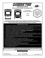
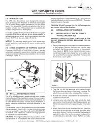
Owner's Manual - Hearth & Home Technologies
Owner's Manual - Hearth & Home Technologies
Owner's Manual - Hearth & Home Technologies

You also want an ePaper? Increase the reach of your titles
YUMPU automatically turns print PDFs into web optimized ePapers that Google loves.
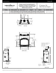
5VentInformationA. Venting ComponentsIn order to comply with applicable codes and productwarranties, use only following venting components:• <strong>Hearth</strong> & <strong>Home</strong> <strong>Technologies</strong> (HHT)• Simpson Dura-Vent (SDV)DO NOT USE FIELD-FABRICATED VENTING COMPO-NENTS. Refer to the venting manufacturer’s instructions.This product is approved to be vented either horizontally,through the side wall or vertically through the roof. Youmay vent through a Class A or masonry chimney if anapproved adapter is used.This appliance is a direct vent heater. All combustion airmust come directly from the outside of the building. Thevent pipe for this unit consists of an inner and an outerpipe. The inner pipe carries the appliance exhaust out ofthe system, and the outer pipe brings fresh combustionair into the appliance.• A round support box/wall thimble or heat shield isrequired when the venting passes through a combustiblewall.• A support box or ceiling fi restop is required when theventing passes through a ceiling.• Roof fl ashing and a storm collar are required whenventing passes through the roof.• Follow instructions provided with the venting for installationof these items.WARNINGFire Hazard.Explosion Risk.Asphyxiation Risk.Do NOT connect this gas appliance to a chimneyfl ue serving a separate solid-fuel or gas burningappliance.• Vent this appliance directly outside.• Use separate vent system for this appliance.May impair safe operation of this appliance orother appliances connected to the fl ue.B. Use of ElbowsCAUTIONALL vent confi guration specifi cations MUST be followed.• This product is tested and listed to these specifi cations.• Appliance performance will suffer if specifications are notfollowed.Diagonal runs have both vertical and horizontal vent aspectswhen calculating the effects. Use the rise for thevertical aspect and the run for the horizontal aspect (seeFigure 5.1).Two 45º elbows may be used in place of one 90º elbow. On45º runs, one foot of diagonal is equal to 8-1/2 (216 mm)inches horizontal run and 8-1/2 (216 mm) inches verticalrun. A length of straight pipe is allowed between two 45ºelbows (see Figure 5.1).Figure 5.1Vertical12 in.8-1/2 in.Horizontal8-1/2 in.C. Measuring StandardsVertical and horizontal measurements were made usingthe following standards.1. Pipe measurements are from center line to center line.2. Horizontal terminations are measured to the outsidemounting surface (fl ange of termination cap) (seeFigure 4.1) on page 9.3. Vertical terminations are measured to the top of the lastpipe before termination cap.4. Horizontal pipe installed level with no rise.Heat & Glo • Paloma • 7031-220 Rev. S • 8/09 11