Wadkin ECA Tenoner Manual and Parts List
Wadkin ECA Tenoner Manual and Parts List
Wadkin ECA Tenoner Manual and Parts List
- No tags were found...

Create successful ePaper yourself
Turn your PDF publications into a flip-book with our unique Google optimized e-Paper software.
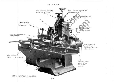
LUBRICATIONLubrication point Con lever cramp.Four lubrica onpoints 'D' (table rollers)Four lubricationpoints 'A' (two oneach motor).zFour lubrication points' C'(two on each scriber).Praising screw.Four lubrication points' A'(two on each motor).www.wadkin.comTwo lubricationpoints' C' (one oneach horizontaladjusting screw).points' A' oncut off sawmotor.One lubricationpoint' onadjusting h<strong>and</strong>wheelof cut off saw.info@wadkin.comFIG. 2.REAR VIEW OF MACHINE.Page 4
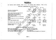
t<strong>Wadkin</strong>SINGLE END TENONER, TYPE E. C. A.PRINCIPAL DIMENSIONS AND CAPACITIESWill admit timber up to ...Will cut tenons at one operationFence may be swivelled 45 degrees for angulartenons.Distance top cutterhead will rise above the tableDistance taken between shoulders of tenons usingturnover stop.Size of tableHeight of table from floorDiameter of cutting-off sawDiameter of horizontal <strong>and</strong> scribing spindlesSpeed of all motors in r. p. m. on 50 cycles .. .Speed of all motors in r. p. m. on 60 cycles .. .Horse power of motors for horizontal cutter headsHorse power of motors for scribing headsHorse power of motor for rear cut-off saw ...Floor space (with stop bar)Net weight in cwts complete machine with cut-offsaw ...Shipping dimensions in cubic feet ...Two motors <strong>and</strong> control gearTwo cutterblocks with cuttersTwo guardsEnglish14" x 4t"5" long5 '0"2'6" X 1'4"2'9 "12 "It"3,0003,6002217'9" x 5'1"20~ (2296 Ibs)112www.wadkin.comDETAILS INCLUDED WITH THE MACHINEMetric356 mm x 114 mm114 mm108 mm1524 mm762 mm x 406 mm838 mm305 mm32 mm3,0003,6002212362 mm x 1550 mm1042 kilos3. 17 cu. metresSet of spannersLubricating pump <strong>and</strong> tin of lubricant.info@wadkin.com<strong>Wadkin</strong> Ltd., Green Lane Works, Leicester. Telephone: Leicester 68151 (7 lines).London Office: Brookfield House, 62-64 Brook Street, W.1. Telephone: Mayfair 7048 <strong>and</strong> 7049.Page 1
HEADSTOCKADJUSTMENTS.TOP TENONING HEAD, Fig. 3.The top tenoning head carriage is moved vertically by rotating h<strong>and</strong>wheel 'A'. This movementis locked by locking h<strong>and</strong>le 'C'. Horizontal adjustment is provided by rotating h<strong>and</strong>wheel 'B' <strong>and</strong>is locked by locking h<strong>and</strong>le 'D'. The rule lE is for setting the tenoning head horizontally. Theguard over the cutters moves with the tenoning head <strong>and</strong> requires no further adjustment.Note that locking h<strong>and</strong>le 'D' also locks the guard in position.BOTTOM TE NONING HEAD, Fig. 3.The bottom tenoning head carriage is moved vertically by rotating h<strong>and</strong>wheel 'F' , which is lockedby locking h<strong>and</strong>le 'H'. H<strong>and</strong>wheel 'G' is used for horizontal adjustment, <strong>and</strong> is locked by lockingh<strong>and</strong>le I J'. The tenoning head is set horizontally by rule 'K'. No adjustment need be made to theguard which is fitted to move with the tenoning head.Note that locking h<strong>and</strong>le' J' also locks the guard in position.CUTTERHEAD ADJUSTMENT.The two heads are set horizontally to give square shouldered tenons by scales <strong>and</strong> pointers setat 0 (zero) on each scale.Unequal shouldered tenons as Fig. 5 can be produced by moving over the top head to the desiredamount on the scale reading.THICKNESSOF TE.NON.FIG. 4.OFWORKUNEQUAL. SHOUTHICKNESS OF TENON.The heads are adjusted vertically up or down to correspond with the depth of work <strong>and</strong> the cutterblocksset to give the desired thickness <strong>and</strong> position of tenon.Take care to lock slides after final setting.www.wadkin.cominfo@wadkin.comH<strong>and</strong> operated brakes are fitted to each tenon head.FIG. 5.Page 7
ATTACHMENT FOR ADJUSTING TWO TENON HEADS TOGETHERFig. 9After the two tenon heads have been set togive the desired thickness of tenon as describedon page 7 <strong>and</strong> the operator wishesto vary its position in the work, the attachmentillustrated at Fig. 9 should be broughtinto use. To do this press lever 'Y' downwardsto raise the plunger 'Z Iwhich bringsa gear into position joining the gears forindependent movement of the heads together.Adjust the combined heads to the requiredposition relative to the table by either h<strong>and</strong>wheel'A' or h<strong>and</strong>wheel 'B' whichever ismore convenient. Before putting the machineto use, take care that the slides aresecurely locked by the locking h<strong>and</strong>les provided.www.wadkin.cominfo@wadkin.comPage 11
METHOD OF DISMANTLING TENON HEAD SPINDLE ASSEMBLY TOREAR BEARING1. Remove end cap EKA 48.2.. Remove locknut No. 2B or 2A.3. Remove brake drum EC 80.4. Remove brake housing EKA 47.5. Remove bearing housing EC 55 or EC 56 <strong>and</strong> bearing.6. Knock out bearing <strong>and</strong> fit replacement SKF 2206 bearing.7. To reassemble, reverse dismantling operation.MIDDLE BEARING8. Repeat operations 1, 2, 3, 4, 5.9. Remove locknut WA 498 or WA 487 <strong>and</strong> cuUerblock EC 182.10. Remove plate EH 29.11. Remove grease retainer EC 79.12. Remove stator frame EC 57 complete with Stator.13. Remove end cover EC 11.14. Remove locknut EC 132 or EC 133.15. Withdraw shaft EC 49 or EC 50 from rear end.16. Remove rotor from shaft.17. Loosen countersunk screw <strong>and</strong> remove locknut No. 7 A <strong>and</strong> 7B.18. Remove grease retainer EH 65.19. Remove bearing <strong>and</strong> fit replacement SKF 2209 bearing.20. To reassemble, reverse dismantling operations.~I~\~:'G/:FRONT BEARINGNEW BEARINGS.21. Repeat operations 1, 2, 3, 4, 5, 9, 10, 11, 12,13, 14, 15.22. Knock out bearing from EH or EH 17/ A<strong>and</strong> fit replacement SKF 2208 bearing.23. To reassemble, reverse dismantlingTO REMOVE STATOR FROM FRAMERemove B. S. P. Pipscrew 'M' from frame<strong>and</strong> knock out stator.IMPORTANTWhen replacing stator, care must be taken to avoiddrilling into the winding". Maximum depth of pipscrewhole is to the tip of the drill.BOTTOM TENON SPINDLE E. C. 50Thread 'N' l"fine thread 14 T.P.I. R.H.Thread 'P' HI! fine thread 14 T. P. 1. R. H.Thread 'Q' It" fine thread 14 T. P. 1. L. H.Thread 'R' ti" fine thread 14 T.P.I. L.H.TOP TENON SPINDLE E. C. 49Thread 'N' 1"fine thread 14 T.P.I. L.H.Thread 'P' H" fine thread 14 T. P. 1. L. H.Thread 'Q' It" fine thread 14 T. P. 1. R. H.Thread 'R' It" fine thread 14 T.P.I. R.H.www.wadkin.cominfo@wadkin.comPage 13.
CUT-OFF SAW SPINDLE ASSEMBLY.METHOD OF DISMANTLING TO FIT NEWBEARINGS,REAR BEARING.1. Remove cap 'A', Fig.122. Loosen countersunk screw <strong>and</strong> removelocknut 'B'.3. Remove bearing housing' C'.4. Knock out bearing from housing <strong>and</strong> fitreplacement.5. To reassemble reverse dismantling operation.FRONT BEARING.6. Remove locknut 'D', collar 'E I,saw <strong>and</strong> collar IF'.7. Remove end cap 'G'.8. Repeat operations 1, 2 <strong>and</strong> 3.9. Withdraw spindle from sawend of frame 'HI.10. Knock out taper pin <strong>and</strong>remove collar' JI.11. Remove rotor from shaft.12. Loosen countersunk screw <strong>and</strong>remove locknut 'K'.13. Remove grease retainer 'LI.14. Remove bearing from shaft<strong>and</strong> fit replacement.15. To reassemble reverse dismantlingoperation.QTO REMOVE STATOR FROM FRAME.Remove t" B. S. P. Pipscrew 'M' from frame<strong>and</strong> knock out stator.IMPORTANT.When replacing stator care must be taken toavoid drilling into the windings.Maximum depth of pipscrew hole is 5/16" to thetip of the drill.CUT OFF SAW SPINDLE E. H. 92.Thread 'N' 1" fine thread 14 T. P. I. R. H.Thread 'P' li" fine thread 14 T. P. I. L. H.Thread 'Q' 1" fine thread 14 T. P. I. L. H.www.wadkin.cominfo@wadkin.comCUT - OFF SAW SPINDLE. ASSE.MBLY. FIG. 12.Page 15
MOULDING ONCUTTERTENON SPINDLE.a 4.1/16 11x 2i" long cutter-44 in section in Fig. 13 ontenon head a wide range of mouldingcan be out. A making up collar <strong>and</strong>5/8 ! dovetail bolts complete with nutwasher are supplied. Cutters as usedscribing heads are suitable for use onrblocks.TRENCHING AND GROOVING HEADS.heads supplied are shown in section14 fitted on the top tenon spindle <strong>and</strong> arecomplete with spacing washers <strong>and</strong> twocollars. The heads are provided withcutters to give clean shoulders inThey can be quickly adjusted toof groove within their range bythe set of spacing washers. Two sizesare made to cut grooves as follows8~fjdiameter cutting circleHead J. P. 541 for grooves ~,,, to 11/16" wideup to 9/16" deep.Head J. P. 543 for grooves 11/16" to H'" wideup to 1" deep.Page 17EQUIPMENTTOP TE.NONSPIN!:)L£..2.-eoLLAP.S wo 1006.;\ l, \FIG. 13SQUARE BLOCK AS USEO ONSCR15 I NGI SET OF SPAOIN~WASHERS WO IOO~-J-4.www.wadkin.comSP1HCLE,s.J' P 541 Ji8 x '516 Wl.tll". x .'l/16 D,U,PJ' P 5 4.3 l~b x lY4 WIPE X (!:lEE?info@wadkin.comEXPANDING TRENCHING HEAD.
CUTTEREQUIPMENTDADO HEADSFIG. 18Outside Cutter. Inside Cutter. Outside Cutter.The Dado head is made up in sets <strong>and</strong> each set consists of two outsidecutters, i" thick, <strong>and</strong> several inside cutters of various thicknesses asillustrated in Fig. 18. A dado head mounted on the top tenon spindle isshown in Fig. 19. Sets are available for cutting grooves up to a maximum.of 2" wide. Depending on the type of work to be undertakencutters up to a maximum of 8 If diameter can be used. The dado headgives a smooth finish, but each cutter has to be placed on the spindleseparately <strong>and</strong> the making up collar <strong>and</strong> outside cutter taken off <strong>and</strong>replaced when adjustments are necessary. For quick set up <strong>and</strong> easymaintenance the exp<strong>and</strong>ing trenching head illustrated in Fig. 14 isrecommended.SPECIAL CUT OFF SAW.TOP TENONwww.wadkin.comFIG 19L'MAX.[.,"....-'i~M'N,caLl-AI'. wOleo!.I...... -.~ --.JI------ll-DADO HEADS AND SET OFSPACING COLLARS,If desired a flat cross cut saw fitted on the top tenon spindle can be used in lieu of a cut off saw.A saw sleeve is fitted on the spindle <strong>and</strong> a locknut used to secure the sleeve to the spindle. Whenthis type of saw is required please state details of the maximum <strong>and</strong> minimum lengths of tenons<strong>and</strong> thickness of timber to be worked so that the correct diameter of saw can be recommended.info@wadkin.comPage 19
11I1LT 1 -:":-::-::-~-~-~-~T~I ~_..".i..-..JIr-1 1I, , Ih 1 111 I11 IiI ,,I1111SLE.E.VE. 'B~r·~+64.1:;~SLE.E.VE 'S'.COMPLETE SET UP FOR TENONING MACHINESleevesSaws Nos. 43, 44; 45 <strong>and</strong> 46 drawinf), SlJec:ial high speed steel on iron se ribin?' cutters 'X'I Sllec:ial hi~h speed steel on iron s c r ib in~ eu t t e r.s 'Y '-,-~~~--",-,-,~~~~~www.wadkin.comIIinfo@wadkin.comPage 21
TENON BLOCK ADZE CUTTER GRINDING ATTACHMENTUSED ON UNIVERSAL CUTTER GRINDER, TYPE N. H.This attachment provides an accurate method of grinding <strong>and</strong> maintainingadze cutters by mechanical methods. consists of a fixed finger workingcutter, the cutterblock assembly being mounted on the swivellingsupplied with the attachment will accommodate any <strong>Wadkin</strong> tenonFIG. 24Fig. 24 shows the mounting of the block.Blocks from machines E. C. A. are mounted on the 1 if! diameter portionThe swivelling table is mounted on the machine table, dividing head <strong>and</strong> tailstockplaced in position.No. 4 Morse taper dead centre is now fitted irito the bore of the dividing head,plete with block being mounted between the two centres in the head tailstoplete table assembly as shown in Fig. 2 The dividing head will beposes so this can be locked. The screws holding the spur cuttersloosened <strong>and</strong> the spur cutters dropped below the cuttingcutters fouling the grinding wheel during the grindingwww.wadkin.cominfo@wadkin.comPage 23
TENON BLOCK ADZE CUTTER GRINDING ATTACHMENT (Continued)r"-\SPUR CUZ7~ / \-"",~ ~~ -~Ill"'"'Fig. 27-L \ 7~RCUT7E.RS.r I //~--/--V--'- J ..Iwww.wadkin.comFIG. 28info@wadkin.comThe edge of the first knife should now be set between the finger <strong>and</strong> the wheel, meansthe rise <strong>and</strong> fall <strong>and</strong> cross traverse to table, the knife should be brought into a position givethe correct grinding angle. The knives are now ready to be ground. Keeping the left h<strong>and</strong> onthe tenon block <strong>and</strong> pressing the knife lightly back on to the finger, the righttraverse the table longitudinally, as shown in Fig. 30.Page 25./
FREE HAND METHOD OF GRINDING TENON CUTTERS TO GAUGE.The template supplied with the machine is used when free h<strong>and</strong> grinding tenon cutters to gauge.It is necessary to ensure that the cutting edge of the cutter is shaped correct to the templateotherwise the tenons will not be flat or parallel.The correct cutter angle of 30 0 should be maintained. This is to give the correct strength tothe cutting edge <strong>and</strong> clearance on the cutting track.Hollow grinding is recommended wherever possible, as a perfect cutting edge is more easilyobtained by stoning. When stoning a flat ground cutter a good edge is more difficult to obtaindue to the tendency to rock the stone <strong>and</strong> leave a convex face. When hollow grinding is carriedout the angle of the cutting edge should be kept as near 30 0 as possible.SETTING UP STAND T. S. S. FOR TENONING HEADS. FIG. 31.Setting up the curved adze cutters on horizontal tenoningheads can be considerably simplified <strong>and</strong> speededup by the use of this st<strong>and</strong>.On the st<strong>and</strong> are engraved a series of curves representingthe cutting track of cutters used on various machines.The wood block is first adjusted so that it is inline with the appropriate curve.Fit the head on the arbor up against the locking collaras shown in Fig. 31. Rotate the cutterblock to checkthat as the edge of the cutter passes the centre of thewood it just touches -all along. The cutter will needadjustment either if it will not pass the wood or if thereis a gap between the cutter <strong>and</strong> the wood.The head is slightly tapered to obtain undercutting ofthe shoulder as described below.CUT OF THE HEADS.The cut of the heads is shown in Fig. 32. The undercuttingof the shoulder, which is exaggerated, is necessaryto ensure clean fitting shoulders when crampedtogether.Fig. 32Page 27PO CKET.www.wadkin.cominfo@wadkin.comSHOUL.DE.R. .
CUTTER GRINDINGFIG. 2TUNGSTEN CARBIDE TIPFIG. 3Cutters should be ground carefully avoiding any overheatingas this will crack or soften cutters so that they willnot st<strong>and</strong> up to the work. A solution of soluble oil <strong>and</strong>water should be h<strong>and</strong>y <strong>and</strong> the cutters should be heldthis occasionally to cool them. This solution will alsoprevent rusting, Cutters should never be allowed to becomediscoloured during grinding, as this indicates overheating.The correct cutter angle of 35 0 for most cutters shouldbe maintained, this is to give the correct strength to thecutting edge. When hollow grinding is carried outangle of the cutting edge should be kept as near 35° aspossible, see Figs. 1 <strong>and</strong> 2.Hollow grinding is recommended wherever possible, as aperfect cutting edge is more easily obtained by stoning.When stoning a flat ground cutter a good edge is moredifficult to obtain due to the tendency to rock the stoneleave a convex face.Good open grain wheels should be used <strong>and</strong> not allowedbecome glazed, as this will cause excessive heat.About 12" (iiameter for new wheels gives the best radiusfor the hollow grind <strong>and</strong> the economic life. ' wheelsused down to 6" leave the grind too hollow.Tungsten carbide tipped cutters should be purchased to theshape required <strong>and</strong> only need re-grinding, In this casecutters should be relieved at 35 0 on steel <strong>and</strong> the tipsfinished with a diamond impregnated wheel at 45 0 asshown, using only very light cuts to prevent cracking.The diamond wheel should not be allowed to touch thesteel backing as this clogs the wheel <strong>and</strong> causes excessiveheat. Where available a copious flow of coolant should beused. They may be honed with a diamond h<strong>and</strong> lap, aswww.wadkin.cominfo@wadkin.comthe cutter becomes dull, until a re-grind is necessary.A thin oil lubricant should be used on the h<strong>and</strong> lap.
DIAGRAM OF CONNE CTIONS D,749TOP TENONMOTOR..I"T A----C T ,: : I 1,, I I ,I I I I: I I :\ I El I I'J.. _ _.J...1r--- -: AI SIIIIIIIII II6TM.TENONMOTO~.,T--- --T', , II I I II I I II I : ~ I e I I'.l. 1../CUT- OFF &AWMOTOR..(TA"-----r',I : I :I I I II II I! I B I)'...t..J....'RETAINCONTACT.TOP &CRIBERMOTOR.(IA-----C-r'; I I \, : I II I I II I I Il I El I I.. al L.IBTM. ~CFl..leERMOTOR....,.--- ---'"""T"( I C 1'\, I II I, I Il I ), _LTYPE. e.15CONTACTOR~.7---- -IBTM. BTM. IL I _________________ T£NON.~&~C~~~IS~a~~~.-r--------------------------------------------------------~...JCONTROl... ~TATION.TERMINAL.. BLOCK MOUNTE.D IN MACHtN<strong>ECA</strong>VITY WHE.N 150LATYNG SWITCH 15 OMI'TTEO,IN!::lTALLATION INS:JTR..UCTION!!:I.F'IT T~IPI...!!: POI..E I!lOI..ATING SWI'TCl-I NEA~ MACI-IINIt UNl..E!:l'!l !lIUP~l..IItO ElY WACKIN l..TO, TO e,r:>I:.CIAl.. O~OE~, ~Oil-lAT ,.~£ EJ..ECTFl.IC.Al.. GEAFI. MAY f'.EAOIl..Y BIl:. ItlOl..ATEO r::'OF\. SN!!FI[CTICfN PUFl.POtlE.!!. !!.F\.INO ~U!:'~l..Y c.Ael..E~TO I5IOl..A'TING .!ioWITCH AND TO l..I, l..2., l..':3 AT C:ONTACTOF\. PANi:L. TJoiII'I.OUCloI-i C.ONOUIT WI-IIC,.. l'oHOUI...C eE. ~c.""'li.witcINTd> THE MACHINE. ANC Se::C.UFl-EO BY ME.AN£:, OF L..OC,KNUTIll. A 1-101...11:. ItI !=IF!.OVIOEO IN "l'HI1: MAc,HINIl:. I"I'I.AM£FOR. TI-I£ CONcurT CA~Fa.YING THE S,UF=F=1...Y C:AB'l...E.~ TO THE. CONTACTOF\'i:I, EN!ilUfl..1t THAT THE CI~EC.TION Oil'~OT~TION l!!o C o !=I.. I=I.E CT 9EFOI=I.I;:'. PUTTING '!'I... U: MACHINE INTO !lIE'AVtc:.II:,"O R.!V£R. ... II: 'AO'TA"I'!ON lNT!!:!:a.CH"'-NGli:.INCOMING S,UF'F'I-Y CAB1...E!1 1..1 ANI:) I..':J AT I:;OI..ATING s;,WITCH.ATINGa tN5TR.UCT!ON~,TO F\.T MACHINE.', CI...O!l£ l!!:10l-ATING SlWITCI-I ANC PI=l.IL&& TI-lIE '!I TA "'T, BUTTON!':! FOR. HI!:AC!!> WHICH AFlo.ER.ECI\U1Fa.E.D TO OP=l!!:.F\ATE. TO !lTOF! Mp...,CI-IINE: l=il=l.£!!J!I '!:ITOF!' BUTTON, TO I...Oc:.K OT/" MACHINE: PFl..E!.!!I ANO TUI'\N'IIToj:l' eUTTON, Tl-tl!::l MU!!T I!IE ~EI..E.A5IEC 8£1='0F\.1 A !ilTAFI..'T CAN BE. MAO!!:'.OV1t~LOAO.=I-IOUI..O THE MACHINE !ITQ!=I OUE TO QV[:I=I..1..QAC WAIT FOFl. A !;'P-IOFl-T TIME. TO AI..1..0W "I')-IE l-IIil:ATE'1"\ C.OH.!O "1'0C.OO\..., TI-4EN &TAI=I..,. IN THE U&U,A.,l. MANNEJ'.\,www.wadkin.cominfo@wadkin.com
low away harmful dust,hi s <strong>and</strong> di t wit aad le t ic I werNo motor can run at its maximum efficiency with its ventilatingduct or control gear covered with dust <strong>and</strong> dirt. Sooner or laterthe resultant overheating will cause serious trouble.Similarly, accumulations of chips <strong>and</strong> dust, in the mechanical parts ofthe machine can interfere with its efficiency. A few minutes a weekfor blowing down all Woodworking Machinery will be amply repaidin better <strong>and</strong> easier running, in increased life, <strong>and</strong> freedom frombreakdown.Blowers can be supplied for single phase A.c. or Direct Currentfor any voltage up to 250.Please state voltage when ordering.www.wadkin.cominfo@wadkin.com
L,,',II'A c,:e1I1 I1\II I_L _______vBOTTOM 'TE:NON. TOP TE:NON C.UT OFF '::JAw'~ __ ~ __ J ___ Y_J. MASLrt:I'1. IJ SiOF'. ieCTTcMTE:.NON.BC~TCMc.o":>£:..MACHINE: !;C THATt.L!::CTF'-ICAl. ""tAR MAV R.E:ADILY SE: I&OLATE:t:I ~OR tN~PE:.CTIONPuRPOSoE:&. BRINe. ~UPPL..Y c.AISL.E..S, ,0 MAIN Dl~C.ONNE:C.T s,wlTCHANO iO LI)WHICH &HOUL.OBY Mi:AN& 01='P.OTA'IONrH!:1-'3 AT MAa.N!:.TIC iO'TAf".l.TE'.f".l.~ THI'&E:M91.1E:!:'.IIII,I/r r,t:I I1 IIIIIII'-,.J ____~/TOP C.OPE:..'1I II If ! ! ''-..J _______ L/80TTOM C.OPE.: P-E:,TA1N, CONTACT.IF*'=tF'-=::-'t++-'-1V Aa. N E.. Ti C.OIL.I:, OVERLOADTRIP~.DUAL VOL TA~r. MOTOR. C.ONNE:CTrON':l.1 OVERLOAD~.WI-4E.N DUA1... VOLTAGe::: WH£N OUAL. VOL.TAGEMOTOR'1.:l Ai=1.E:' S.UPl"'l..l£D WITH MOTOR':> ARE: ~UF>PLIE.O WITl-!~ L.E.AO~ THE.. CONNe:::CTION!. 6l..e:.ADS nu: c'ONNl!:CTl0N~SHOWN et.LOW A~e::: SHOWN eE.LOW ARE,NEe E:,."S,ARY :-~440 VQl..T~. STAR - J£lTAR- eaOVOLT5. OE.LTA-www.wadkin.cominfo@wadkin.comDIAGRP.M OF CONNECTIONS 0.59,;MOTOR'e>.
ELECTRICAL INSTALLATION INSTRUCTIONSThe cabling between the motor <strong>and</strong> the control gear has been carried out by <strong>Wadkin</strong> Ltd., <strong>and</strong>it is only necessary to bring the line leads to the machine for it to be put into service. Thisshould be done as follows :-(1) Fit triple pole isolating switch near the machine, unless this has been suppliedto special order by <strong>Wadkin</strong> Ltd. , when it will be fitted <strong>and</strong> connected themachine.(2) Connect the line lead to the appropriate terminals, see diagram. The cablesshould be taken to the machine in conduit <strong>and</strong> secured to the control gear bymeans of locknuts.(3) Connect solidly to earth.(4) Close isolating switch <strong>and</strong> press start button. If machine does not rotate in theright direction, interchange any two incoming line leads.FAILURE TO START(1) Electric supply is not available at the machine.(2) Fuses have blown or have not been fitted.(3) Isolating switch has not been closed.(4) Lock-off or stop button has not been released.STOPPAGE DURING OPERATION AND FAILURE TO RESTART(1) Fuses have blown.(2) Overloads have tripped. They will reset automatically after a short time, <strong>and</strong>the machine can be restarted in the usual manner.ADJUSTMENTFor a finer overload setting, set the load indicator to a lower value, <strong>and</strong> vice-versafor a less fine setting.www.wadkin.comGENERALCheck the earth connection from time to time. Users are recommended to display inan appropriate position in the maintenance department <strong>Wadkin</strong> Electrical MaintenanceInstruction Card, No. 356, which is issued gratis on application.info@wadkin.com
HONEHONEGROUND CUTTERFIG. 5___""'11FIG. 6SHAPED HONESHAPEDCUTTERHONING.Cutters must have a razor sharp cutting edgebefore commencing to cut. To obtain thisedge it is necessary to hone the cutters usinga 142 carborundum slip stone. This will ensurea good finish on the wood <strong>and</strong> an easyfeed.Dull cutters give a poor, rough <strong>and</strong>plucked out finish <strong>and</strong> make it difficultthe job past the cutters. Honingby a reciprocating or rotary motion on thecutter, using a little paraffin to give !the stone. The honing stone is a muchgrit than the grindwheel <strong>and</strong> leaves awww.wadkin.comkeen edge. A number of honing stonesdifferent shapes, e. g. round or square sticksinfo@wadkin.comwill be found helpful in honing shapedrs,
TENON BLOCK ADZE CUTTER GRINDING ATTACHMENT (Continued)Take an initial roughing cut of one or one-<strong>and</strong>-a-half thous<strong>and</strong>ths of an inch on one knife, turnthe block round to the next knife <strong>and</strong> take the same cut, proceeding thus until both knives havebeen ground. After grinding completely round the block, take successive light roughing cutsuntil both knives are sharpened. On the roughing cuts use a rapid table traverse. On the finishingpass, reduce the cut to one-half thous<strong>and</strong>th of an inch <strong>and</strong> use a slow table traverse to ensurea keen cutting edge <strong>and</strong> uniform blade height.Finally check the setting of the knives on the tenon block setting st<strong>and</strong>.FIG. 29. Showing the tenon blocks set up forgrinding.www.wadkin.cominfo@wadkin.comFIG. 30. Showing the actual operation of grinding,indicating the best position for the operator.Page 26
TENON BLOCK ADZE CUTTER GRINDING ATTACHMENT (Continued)The finger assembly is now set up as shown in Fig. 25. The tip of the finger should be setapproximately t" below the centre of the wheel, on the cutting side of the wheel (left-h<strong>and</strong>side with the wheel running clockwise) <strong>and</strong> 1/32" away from the wheel as shown in diagramFig.26.Generally, tenon blocks are made slightly conical <strong>and</strong> due to this the swivelling table must beset over to give this coned effect, as shown exaggerated in Figs. 27 <strong>and</strong> 28. The amount thatthe table is set over depends upon the make of block, but for <strong>Wadkin</strong> blocks the amount is onedivision of the scale on the left-h<strong>and</strong> side of the swivelling table, equal to a movement of 1/16 n.The direction in which the table is set over depends upon which way the block is coned. On all<strong>Wadkin</strong> blocks the spur cutter end of the block is the bigger diameter, therefore the settingsare as shown in Figs. 27 <strong>and</strong> 28.NOTE. - It is recommended that when a block has been ground, tried on the setting-up st<strong>and</strong><strong>and</strong> found correct, that the position of the swivelling table relative to the machine table bemarked by scribe lines to facilitate easier <strong>and</strong> quicker set-ups for subsequent regrinds,!\NGbE. OF fINGE.RSE-" "0 CL-E.ARBOOr OF eL-OCK.Fig. 25Fig.26----"-_. )(,oa:ill...II::..------'T- ill...www.wadkin.com
CUTTEREQUIPMENTINSERTED TOOTH GROOVING SAWSFIG. 21High speed steel inserted tooth grooving sawsare supplied for working of narrow grooves,i. e. in up to approximately~" wide, where anaccurate <strong>and</strong> clean groove is required. Thesaws have a very long life <strong>and</strong> the teeth can berenewed when worn out. Where necessaryTungsten Carbide tipped saws can be suppliedfor working plywood, etc.An inserted tooth grooving saw fitted on the toptenon spindle is shown in Fig. 22. A spacingcollar <strong>and</strong> a sleeve are provided when this sawis supplied. A similar set up can be fitted oneither the top or bottom scribing spindles asshown in Fig. 23. Set ups can be supplied tosuit customers own particular work, in whichcase samples or a dimensioned sketch of workto be produced should be sent to us when enquiring.KEY,TOP TE.NONSPINJ:lLE..TOP AND BOTTOMSCI'.IBIN6 SPINDLE.WO 1006.SLEEVE "5:FII;·22INSERTED TOOTH GROOVING SAWS.SCR1B1NG SPINDLE OUTSIDE coLUMNlrOIA.MAX.ISLEEVE ·B·.www.wadkin.cominfo@wadkin.comINSERTED TOOTH GROOVINGSAWS.Page 22FIG.23.
BOT"t'DM SCRIBJN!!jCUTTf:.R61..0CK.444.3BOTTOM HORIZONTAL HE.AC.CASEMENT WINDOWS.Fig.20---- --------1--+--+--------~~r_~~511..1..www.wadkin.comIII'-__________-L __ ~ ____ L_ __ ~These diagrams show set of saws <strong>and</strong> cutters for working frames <strong>and</strong> sashes ofE. J. M. A. heavy type casement windows. The grooving is worked using highspeed steel inserted tooth grooving saws mounted on special sleeves fitted on topor bottom scribing spindles. Shaped scribing cutters can be supplied for use onthe bottom scribing cutterblock. Complete set ups can be supplied to suitcustomers own particular joints, please send detailed sketch or samples whenenquiring.Page 20info@wadkin.com
CUTTEREQUIPMENTTRENCHING AND GROOVING HEADS.A heavy type wobble saw unit fitted on the bottomscribing spindle is shown in Fig. 15. The saw is 10 ITin diameter <strong>and</strong> is fitted on a screwed sleeve whichis secured to the spindle by a single locknut.Thewobble saw unit can be quickly adjusted for cuttinggrooves between the limits i" full to 1 i" wide <strong>and</strong> amaximum depth of 21".Two types of wobble saw unit as shown in Figs. 16<strong>and</strong> 17 for fitting on top tenon spindles can besupplied.The heavy type wobble saw unit with a screwedsleeve is mounted on the spindle as shown in Fig. 16.This wobble saw unit with a maximum diameter of8" can be quickly adjusted for cutting grooves betweenthe limits of i" full to 1. 7/16" wide.The light type wobble saw unit is accommodatedon the spindle as shown at Fig. 17, two making upcollars being required. The light type has a maximumdiameter of 8 fI. Grooves between the limitsof i" full to 1i n wide can be cut.The wobble saw is used when it is not necessary tohave a fine finish with clean shoulders in the grooves<strong>and</strong> where the bottom of the grooves do not need to be flat.EQUIPMENT I-SL.EEVE I...H. THC. Q M 10. MOCI"''''O TO .s Cl 46551- 10"OlA. WOBBI..E SAW.COLLAR. WO 1004.TOP T.E.NONSPINCLE..FIG. 16.HEAVY TYPE WOBBLE SAW.COLLAI'. WO 1006.COLLAI'. WO .9 6.9. COLLAR WO 100I./www.wadkin.comTOP TENONSPIN!:>!...E..info@wadkin.comFIG. 17\\QM Jc..1Ixl«Irl~Cl·00HEAVYTYPE:WOeSI..E SAw UNIT "'TT",O ON BOTTOM SCRIBlNG SPINDI..E.Page 18LIGHT TYPE WOBBLE SAW,
CUTTEREQUIPMENTTENONING CUTTERHEADS.Two tenon cutterheads are supplied as st<strong>and</strong>ard equipment complete with High Speed Steelon Iron adze cutters <strong>and</strong> high chrome steel spur cutters.Top tenon cutterheadBottom tenon cutterheadSCRIBING OR COPE CUTTERHEADS.Part No. EC182Part No. EC183The cutterblocks are 4. 1/16" squaresection dovetail slotted, <strong>and</strong> aresupplied complete with one pair ofHigh Speed Steel on Iron scribingcutters per block, also four dovetailhead cutterbolts.Part No. CuttersTop scribing cutter head EKA182 VM4Bottom scribing cutter head EM244 VM3Spare dovetail headed bolts for use withscribing cutterblocks - Part No. QW5with nuts QAF24 <strong>and</strong> washers QAF46.Adze cutterI-pr. EC176I-pr. EC177Spur cutterI-pr. EK155I-pr. EKlDETAILS OF CUTTERBLOCKCUTTERBLOCKSSt<strong>and</strong>ard tenoncutterblockSquare block ontenon headSquare block onscribing headCutting circleMini- ·MaxiNormalmum mum6%"7i" 6%n 81..n27i" 6:£-" gnFor range of cutters suitable for scribing blocks see VM range in Section C, Page 10, ofour Tools <strong>and</strong> Accessories Catalogue No. 745. .CUT OFF SAW.www.wadkin.cominfo@wadkin.comSt<strong>and</strong>ard cut off saw supplied for use on this machine is 12" diameter, Part No. QS2.Page 16
SCRIBING OR COPE SPINDLE ASSEMBLYME THOD OF DISMANTLING TO FIT NEWBEARINGS,REAR BEARING.1. Remove bearing end cover 'A', Fig.112. Loosen countersunk head screw in ballbearing locknut 'B' <strong>and</strong> remove locknutfrom shaft.3. Remove rear bearing housing' C' completewith bearing.4. Knock out bearing from housing <strong>and</strong>fit replacement.5. Reverse dismantling operations to reassemble.FRONT BEARING.6. Remove rear end cover <strong>and</strong> locknut asoperations 1 <strong>and</strong> 2.7. Remove front bearing end cover 'D'<strong>and</strong> remove bearing housing screws.8. Withdraw shaft from cutterblock end ofhousing <strong>and</strong> remove grease retainer 'E'<strong>and</strong> bearing housing' F'.9. Knock out taper pin from rotor retainingcollar 'G' <strong>and</strong> remove collar <strong>and</strong>rotor from shaft.10. Loosen countersunk head screw in frontball bearing locknut 'H' <strong>and</strong> remove locknut<strong>and</strong> grease retainer' J' from shaft.11. Remove bearing from shaft <strong>and</strong> fitreplacement.12. Reverse dismantling operations to reassemble.TO REMOVE STATOR FROM FRAME.Remove t" gas pipscrew 'K' from statorframe <strong>and</strong> knock out stator.IMPORTANT.When replacing stator, care must be takento avoid drilling irito the windings. Maximumdepth of pipscrew hole is 5/16" to the tip ofthe drill.BOTTOM SCRIBING SPINDLE E. C. 129.Thread'L' 1" fine thread 14 T. P. 1. R. H.Thread 'M' It" fine thread 14 T. P. 1. R. H.Thread 'N' 1" fine thread 14 T. P. 1. L. H.TOP SCRIBING SPINDLE E. 0.312.Thread'L' 1" fine thread 14 T. P. 1. L. H.Thread 'M' It" fine thread 14 T.P.I. L.Thread 'N' 1" fine thread 14 T. P. 1. R. H.www.wadkin.cominfo@wadkin.comPage 14SCRIBING OR COPE SPINDLE ASSEMBLY.Fig. 11
BALL BEARING LISTMakers Size NumberNumber Outside PerBore Diameter Width Machine Where used on machineSKF. 6 30 mm 62 mm 20 mm 2 1 - Top tenon spindle1 - Bottom tenon spindleSKF.2208 40 mm 80 mm 23 mm 3 1 - Driving end top tenon head,1 - Driving end bottom tenon1 - Driving end cut off sawSKF.2209 45 mm 85 mm 23 mm 4 1 - Non-driving end top tenon head1 - Non-driving end bottom tenon head1 - Driving end top scriber1 - Driving end bottom scriberSKF. HMS I" 2~" 1."4 3 1 - Non-driving end top scriber1 - Non-driving end bottom scriberwww.wadkin.com1 - Non-driving end cut sawSKF. HLS6 1."4 1i" 9/16" 4 Spindle for table rollersinfo@wadkin.comSKF.08 1" 1t" ~"8Thrust2 1 - Top tenon raising screwwasher1 - Bottom tenon raising screwPage 12
THE TABLE.The table is mounted on four ball bearing rollers. If due to wear there is any play in the tablethe nuts' Z', Fig. 2, should be tightened, so that perfect alignment with the cutterblocks is alwaysmaintained.The centre sliding table is locked in position by locking h<strong>and</strong>le 'V', Fig. 3. A spring stop runsthe full length of the sliding table <strong>and</strong> is released into pOSition by loosening the wing nuts whichhold the stop under the table. On both sides of the sliding table a channel is cut so that the stopmay be fitted in two positions. The springs have to be retained in position whilst transferringthe stop.A lever cramp is provided which can be adjusted for various widths <strong>and</strong> thicknessesscrewing the two locknuts 'W', Fig. 3, either up or down as necessary.TABLE FENCE.The table fence is provided with a turn over stop. The fence can be set at angles 0 0 45°means of the series of holes tapped in the back table <strong>and</strong> secured by locking nut' ,Fig. 3.DEAD STOP AND TURNOVER STOP.dead stop is provided for use in conjunction with the turn over stop on the fence. This stop isfor locating the work of producing tenons in order to cut the tenon off the correct length.complete the tenons at both ends of the work the material is turned round <strong>and</strong> positionedcorrect length by use of the turn over stop on the fence. When this operation isdead stop can be allowed to fall down so that it is clear of the work by unlocking locking'Y', Fig. 3. The dead stop is adjustable for length of material along a bar <strong>and</strong> can lockedwhere desired. Similarly the turn over stop is adjustable along a rod.SLIDING TABLE.www.wadkin.comThe sliding table is provided with a spring stop running the full length for the purpose of loadingthe table with narrow stock, such as sash bars. The stop can be placed in either of the twogrooves in the table to accommodate any length of stock.info@wadkin.comPage 10
HEADSTOCKADJUSTMENTS.( Continued)TENONING HEAD SPINDLE END.The spindle end is shown in Fig. 6. The cutterblocksare driven with the key <strong>and</strong> locked in positionwith hexagon nut. A special box spanner isprovided for locking the nut. Two holes in thecutterblnck are used to take a tommy bar to holdthe spindle while locking the nut.TOP SCRIBING OR COPE HEAD.The top scribing head is carried on a slidewayfixed to the top tenoning head <strong>and</strong> will thereforemove up <strong>and</strong> down when the tenoning head isadjusted. Further vertical adjustment to thescribing head is obtained by rotating star h<strong>and</strong>wheel 'L', Fig. 3. This movementlocking h<strong>and</strong>le' ,Fig. 3. Cross adjustment to the scribing head is obtainedh<strong>and</strong>wheel 'P', Fig. 2, which is locked by locking h<strong>and</strong>le 'Q', Fig. 3.BOTTOM SCRIBING OR COPE HEAD.cll!!. 6. TENONING HE:.AD SPINDL!:: E:NO.www.wadkin.comThe bottom scribing head is mounted <strong>and</strong> operated similar to the top head with its maintaken from the bottom tenoning head. Further vertical adjustment to the head is takenh<strong>and</strong>wheel 'N', Fig.2, <strong>and</strong> is locked with the tee locking h<strong>and</strong>le '0', Fig. 3. s usprovided by rotating star h<strong>and</strong>wheel 'R', Fig. 2, <strong>and</strong> locked with locking h<strong>and</strong>le'S', Fig. 3.F"ORSTM. TENONinfo@wadkin.comPage 8
A ______________ __EBuHoH<strong>and</strong> brakesLDGuardwww.wadkin.comSpring Stopin sliding table.TurnoverstopxFenceinfo@wadkin.comvPage 6FIG. 3.FRONT VIEW OF MACIDNE.
INSTA L LATION.The machine is despatched from the Works with all bright surfaces greased to prevent rusting.This must be removed by applying a cloth damped in paraffin or turpentine.FOUNDA TIONS.Rag bolts 5/8" (16 mm) diameter should be used to fix the machine to the floor, but these arenot supplied by <strong>Wadkin</strong> Ltd. unless specially ordered. If the mill floor consists of 4" (to 6" (150 mm) solid concrete no special foundation is necessary. The outline in Fig. 1 givesdetails of bolt positions <strong>and</strong> clearances required. Cut 6" (150 mm) to 8!! (200 mm) squareholes in the concrete <strong>and</strong> run with liquid cement to fix. The machine should be carefullylevelled before fixing <strong>and</strong> again after final fixing to ensure that no distortion has taken place.WIRING.www.wadkin.comFor complete cabling instructions <strong>and</strong> wiring diagrams see pages 30 to 32.info@wadkin.comPage 2
SPARE PMTS BOOKLET/, :~--- -'/'.CONTENTS1. Basic ordering requirements.2. Sample type order.3. <strong>List</strong> of item nwnbers <strong>and</strong> description of item.4.. Drawing showing -item numbers ..<strong>ECA</strong>SINGLE END TEHOJUNGMACHInEwww.wadkin.cominfo@wadkin.com\ ....... j\'-"r AnTe TNT, 'T' n (;RTCTCN LANE WORKS. LEICESTER. ENGl 'J D.
SPARE PARTSShould spare parts be required due to breakage or wear full particularsincluding the machine <strong>and</strong> test nu.'nber must be giveno This infonnationison the nameplate attached to the' mac'hine .<strong>and</strong> will be similar to thepicture .below.Please s'ee the next page for sample detail of how to order spare parts ~www.wadkin.cominfo@wadkin.com
SAMPLE TYPE ORDERMACHINE:<strong>ECA</strong>MACHINE NO: 1407TEST NO: 68975PARTS REQUIRED1 - EC2 50/EC8 FENCE .1 - EC250/EC32 SLIDE FOR TOP l~NON1 - EC250/EC70 GEAR1 - EC250/EC126 SPRING FOR CRAMP PLATE1 - EC250!EC215 SPACING COLLARwww.wadkin.cominfo@wadkin.com
<strong>ECA</strong> SPARE PARTS LISTEC250/ECl/AEC250/EC3EC250/EC4EC250/EC5EC250/EC6BASEL.H. TABLE WAYR.H. TABLE WAYL.H. TABLER.H. TABLEEC250/EC7EC250/EC8EC250/EC9EC250/EC10EC250/EC11EC250/EC12EC250/EC20EC250/EC21EC250/EC22EC250/EC23EC250jEC32EC250/EC33EC250/EC38/AEC250/EC49EC250/EC50EC250/EC55EC250/EC56EC250/EC57EC250/EC70EC250/EC72SLIDING TABLEFENCECOVER FOR BASE (CONTACTOR)SLIDE FOR CUT OFF SAWFRONT END COVER FOR TENON HEADPILLARBRIDGE FOR DUPLEX ELECTRIC CLAMPECCENTRIC FOR DUPLEX ELECTRIC CLAMPADJ. CLAMPCLAMP HANDLESLIDE FOR TOP TENONSLIDE FOR BOTTOM TENONGEAR BRACKETTOP TENON SPINDLEBOTTOM TENON SPINDLEwww.wadkin.comBEARING HOUSINGBEARING HOUSINGSTATOR FRAMEinfo@wadkin.com. GEARIDLER GEAR SHAFTEC250jEC73EC250/EC74EC250jEC75OPERATING LEVERVERT. ADJ. SCRBv (TOP TENON)VERT. ADJ. SCREW (BOT'1'o)l TENON)EC250/EC76HEX tl 1 )SCREW FOR GEAR BRACKETEC250/EC78HANF ·EL SHAFT
EC250/EC79EC250/EC80EC250/EC8lEC250/EC82EC250/EC83EC250/EC84GREASE RETAINERBRAKE DR UI>!PIVOT PIN FOR OPERATING LEVERPIN FOR IDLER GEAR SIIAFTBUSH FOR IDLER SflAFTWASHER FOR IDLER SIIAFT ,EC250/EC96EC250/EC97EC250/EClOl 'EC2 5 O/ECl 02EC250/ECl03EC250/ECl04EC250/ECl05EC250/ECl06EC250/ECl07EC250/ECl08EC250/ECllOEC250/EClllEC250/EC1l2EC250/EC113EC250/EC114EC250/EC1l5EC2 5 0/ECl2 0EC250/ECl2lEC250/E,Cl22EC250/ECl23GUARD FOR CUTTERDLOCKGUARD FOR CUTTERDLOCKSTAYBOLT FOR TABLE IvAYSTABLE ROLLERS-(END CAP FOR TABLE ROLLERSBUSH FOR TABLE ROLL SPINDLESPINDLE FOR TABLE ROLLERSLIP PLATE FOR TABLEGUIDE STRIP FOR TABLESTOP STRIP FOR SLIDING l~BLESTOP BARTABLE STOPFI.AT SCRAPERSHAFT FOR END smpFELT FOR SCRAPERSwww.wadkin.comHORIZONTAL ADJUSTING SCREW FOR BOTTOM SCRIBERSTUD FOR CRAMP PLATE'info@wadkin.comSLEEVE FOR STUDCONNECTING LINKPIN FOR CONNECTING LINKEC250/ECl24EC250/ECl25FULCRUM PIN (5-~"FULCRUM PIN (3-~"LONG)LONG)EC250/ECl26EC250/ECl27EC250/ECl28,EC250/ECl29SPRING FOR CRAMP PLATECRAMP PLATERUBBER PRESSURE STRIPSBOTTOM SCRIBER SPINDLE
EC250/EC132EC250/EC133EC250/EC176EC250/EC177EC250/EC182EC250/EC183LOCKNUT FOR TOP TENON SPINDLELOCKNUT FOR BOTTOM TENON SPINDLE,5" TENON CUTTER (TOP HEAD)5" TENON CUTTER (BOTTOI! HEAD)TENON HEAD FOR 5" LONG TENONS (TOP)TENON HEAD FOR 5" LONG TENONS (BOTT0.\j)EC250/EC205EC250/EC209EC2 5 0/EC215EC250/EH13EC250/EHl7/AEC250/EH18/AEC250/EH29EC250/EH32EC250/EH34EC2 5 0/iliH3 5EC250/EH36EC250/EH37EC250/EH63/AEC250/EH65EC250/EH88/AEC250/EH91/AEC250/EH92EC250/EH99/AHINGE PLATE FOR GUARDHINGE PIN FOR GUARDSPACING COLLARNUT FOR TRAVERSE OF SPINDLE HOUSINGSPINDLE HOUSING FOR TOP TENONING HEADSPINDLE HOUSING FOR BOTTOM TENONING HEADCOVER FOR STATOR FRAMESHORIZONTAL INDICATOR (T & B HEADS)SLIP COVER -SLIP COVER -WEAR STRIPFRONTREARPIN FOR TOP AND BOTTOM CUTTER GUARDSSTOP HOLDERwww.wadkin.comGREASE RETAINER FOR TENONING SPINDLESUPPER SAW GUARD (BELOW TABLE)info@wadkin.comLONER SAW GUARD FOR C/O SAW BEL01'l TABLESAW SPINDLEINTERMEDIATE SLIDE FOR TOP SCRIBEREC250/EH100EC250}'EHl02/AEC250/EHl03/AEC250/EHl04EC250/EH105EC250/EH106INTERMEDIATE SLIDE FOR BOTTo.\I SCRIBERFRONT MOTOR COVERREAR MOTOR COVERSLIDE BRACKETFRONT END COVERREAR END COVER
EC250/EH122EC250/EH123EC250/EH126VERTICAL TRAVERSE SCREW FOR TOP SCRIBERHORI ZONTAL ADJUS TI NG SCREW'MODIFICATION TO TENONING SPINDLEEC250/EJ45STOPEC250/EJ91EC250/EJ95EC250/EJ97EC250/EJ99EC250/EK61EC250/EK206/AEC250/EK233EC250/EKA4BEC250/EKA13EC250/EKA47EC250/EKA48EC250/EKA62EC250iEKA68EC250/EKA75EC250/EKA182EC250/EKA252CLAMP POSTPIVOT PIN FOR FENCEPIVOT PIN FOR STOPBOLTSTOPBEARING NUT FOR SCRIBING APPARATUSNUT FOR INTERMEDIATE SLIDE FOR SCRIBING SPINDLEBOTTOM CUTTER CARRIAGEBRAKE SHOEBRAKE BOXEND CAP FOR BRAKE BOXVEE STRIP FOR CARRIAGEwww.wadkin.comCOLLAR FOR CUTTER SPINDLECOLLAR ,FOR CUTTER SPINDLEinfo@wadkin.comTOP·SCRIBING CUTTERBLOCKNUT FOR SA\,! SPINDLEEC2:,:' '2KA254EC2S' .. :A319EC25u, '.:r~\337EC250/EKA338STUD FOR OPERATING BRAKE.COllAR FOR BUSHPUSH BUTTON PLATEPUSH BUTTON PLATEEC250/EL461VEE STRIP FOR BOTTOM SCRIBER INTER SLIDE
EC250/E023AEC250/E046AEC250jE047EC250/E048EC250/E0307EC250/E0312STATOR FRAME FOR L.H. CROSS CUT UNITSTATOR FRAME FOR T & 'B SCRIBERS. CUTTERBLOCK BEARING HOUSINGCUTTERBLOCK BEARING END .COVERHORIZCi'lTAL SCREW FOR CROSS CUT SAWSPINDLE FOR LEFT TOP SCRIBEREC250/1AEC250/1AEC250/1AEC250/1AEC250/1AEC250/1BEC250/1BEC250/1BEC250/1BEC250/1BEC250/1CEC250/1EEC25 0/2EC250/2EC250/2AEC250/2AEC250/2AEC250/2AEC250/2BEC250/2DEC250/3EC250/3BEC250/5EC250/5BBALL BEARING LOCKNUT1110 BALL HANDLECLAMP NUT LEVERSAlv COLLARTEE LOCKING HANDLEBALL BEARING LOCKNUTlWO BALL HANDLECLAMP NUTHANu,vHEELSAW COLLAR1110 BALL HANDLElv/O BALL HANDLEGREASE RETAINERwww.wadkin.comHORN HANDLEBALL BEARING LOCKNUT·HANDWHEELinfo@wadkin.comPIPSCREWSLIDE LOCKSCRElvBALL BEARING LOCKNUTSTAR HANJJ,vHEELCOLLARHANUVHEELCOLLARBALL BEARING LOCKNUT
EC250/7AEC250/7BEC250/11AEC250/62EC250/92EC250/102BALL BEARING LCCKNUTBALL BEARING LOCKNUTj-IANVtlHEELGREASE RETAINERGREASE RETAINERGREASE RETAINEREC250/AF39EC250/CR3EC250/CR4EC250/EM244EC250jLM77EC250/ME136EC250/PC2EC250/QS2EC250/RD43EC250/SKF.08EC250/SKF2206EC250/SKF2208EC250/SKF2209EC250/SKFRL56EC250/SKF .RM8EC250/SSR4EC250/SSR40EC250/WA497LOCKNUT FOR PIVOT PINSTAIL END HOUSINGEND CAP FOR TAIL ENDTOP SCRIBING CUTTERBLOCKBUFFER FOR SLIDELEVER PLUNGER SPRINGOIL NIPPLE12" FLAT CROSS CUT SAWPIVOT PINSKEFCO BEARINGSKEFCO BEARINGSKEFCO BEARINGSKEFCO BEARINGwww.wadkin.comSKEFCO BEARINGSKEFCO BEARINGBRASS SCALE 3*" x g" x 20 B.W.G.info@wadkin.comBRASS SCALE 3*" x g" x 20 BWGNUT FOR SCRIBER SPINDLEEC250/I'IA498EC250/YK91NUT FOR SCRIBER SPINDLE'BRAKE LINING -
I'f\II'CIIW. DW.I._ .... ...- ""II'o.CJTlU.0:101~==@.~~.----------""~[MO"!8I'. DAl.",... .-n~ c.1IT'tta ~.I'OIO'T'Ok 0Il1'I''''''' "IOP ..... D IOT'ftIM ,s, ........ "" .... a.~~MMG\.IT-""_.otA.NIf.TIJI. (W ~~ ~" IC.I\D6.DUt.ME1'IA 11' TD~ AND IO'M'OM 6CJJ1olNG HIAD ••rMA.IWI:TU. 0# MM C!1'f-flf' I/IW/.WAAU;TU.. ., ;AaIMN8~.s 1'0'" 'JDI' NooIDo ."tM.~$Z ... iI'!~HI'·I!z.H-'.64. illS M,M.J.-(teMM.jIt"(*_)'f·':t7!1-.)--.. LANQTM (If' 'TIEHON. S"(IZ'7M.M.1~. ftGCJ, KCfIOIroI l+'x+Ji (Si6"""~MM"Ha: ""1010 ""Ml.Io 'TIi'.-....Hl:1~ ., '!MI.L I'M ..... ~.If' +1 SINGLE EN!> "TENOmp. T'lPE tCA.(ID"'" "II/'2.,,~(aU"''''Jwww.wadkin.cominfo@wadkin.com'flISDC.Sr 09'1 HST10N !HM' M-re ee.w ".,., LNT;Ir§lt+I : ., A "*+ IN..... ·;' ... HH'.GENERAL ARRANGEMENT OF SNGLETENDNER-TYPE E.C.A,END.......,.. EC250
'.,,'""== f"'I~.. ~\!V-~~~DII¥I.I __ ""''''~u.~DAl_..-..rJ~ ~ MP.DLz •...,!MO'T'M OIoM ..... "lOP' _110 ~ "CA]""'; HI ....... ,...,... DIUWO.Ia AUI. CUT-on: -". IJzH'"~ rI# lCliUUl'C'TItt.I. CU'MP. HU.D6.. R llfS-.jtll'''.~tt'' • '!'Vii' AIroID aO'T"TDM 6~a1NG H ........ ft(~.....-.JDIoOt.IYC.TUI. 06' UM C\IT-.. ~1e."£M6_1~TU."~.....a .. 1'0111, 'JIfO _tIo a"IM.6tA.lMA.s If·,n!! ........... }1IoWII.. L.INC'T14 ~ UNON.S"(I.n_JMoMo.t.'TDCJ.~ 1+· ..... li£t.u: ll'14M ...1"I"'ICl WI"~ $W'fVI..r. ",._HE.GMT ., 'boaI..I. I'IWM I'UJM..+.'J.f~+!; .'NoLi END ""NONE,.. TYP£ £CA.www.wadkin.comj'~. , .. (831MM)info@wadkin.com'.