14238 2000 Articulator_BW - Whip Mix
14238 2000 Articulator_BW - Whip Mix
14238 2000 Articulator_BW - Whip Mix

You also want an ePaper? Increase the reach of your titles
YUMPU automatically turns print PDFs into web optimized ePapers that Google loves.
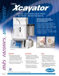
<strong>2000</strong> Series<strong>Articulator</strong>andQuickMountFace-BowInstructionManual
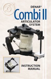
WHIP MIX <strong>2000</strong> SERIES ARTICULATORSModel 2240Model 23402
CONTENTSINTRODUCTION 5OBTAINING FACE-BOW REGISTRATION 6I. Preparing Face-Bow 6II. Preparing Face-Bow Fork 7III. Positioning Face-Bow on the Patient 9IV. Removing Face-Bow from the Patient 11V. Obtaining Interocclusal Records 12DIRECT MOUNTING THE MAXILLARY CAST ON <strong>2000</strong> SERIES ARTICULATORS 16I. Preparing the <strong>Articulator</strong> for Mounting Casts 16II. Placing a Direct Mounting Face-Bow on the <strong>Articulator</strong> 19III. Mounting the Maxillary Cast with a Direct Mounting Face-Bow 21INDIRECT MOUNTING THE MAXILLARY CAST ON <strong>2000</strong> SERIES ARTICULATORS 23I. Preparing the Face-Bow and <strong>Articulator</strong> for Mounting Casts 23II. Placing the Face-Bow Transfer Assembly on the <strong>Articulator</strong> 24III. Mounting the Maxillary Cast 25MOUNTING THE MANDIBULAR CAST 26SETTING THE CONDYLAR GUIDANCE OF THE ARTICULATORUSING LATERAL INTEROCCLUSAL RECORDS 30SETTING THE CONDYLAR GUIDANCE OF THE ARTICULATORUSING PROTRUSIVE INTEROCCLUSAL RECORDS 35TECHNIQUE FOR FABRICATION OF A CUSTOM INCISAL GUIDE TABLE 36COMPLETE DENTURE TECHNIQUE 40I. Constructing Occlusion Rims 40II. Preparing the Face-Bow Fork 40III. Preparing the Face-Bow Armamentarium 41IV. Positioning the Face-Bow 41V. Obtaining Interocclusal Records 42VI. Preparing the <strong>Articulator</strong> for Mounting Casts 43VII. Mounting the Maxillary Cast 433
VIII. Mounting the Mandibular Cast 45IX. Setting the Adjustable Incisal Guide Table 45X. Obtaining Protrusive Record 46XI. Fabricating a Remount Index 47XII. Remounting Casts 48XIII. Completed Dentures 48WHIP MIX RECORDING SYSTEMS 49TRANSFER OF CASTS TO ANOTHER ARTICULATOR 50INTERCHANGEABILITY WITH THE MODEL 2240 AND 2340 ARTICULATOR 51REMINDERS AND SUGGESTIONS 52MAINTENANCE 53<strong>2000</strong> SERIES ARTICULATORS PARTS LISTS 54Model 2240 <strong>Articulator</strong> 54Model 2340 <strong>Articulator</strong> 55WHIP MIX FACE-BOW PARTS LISTS 56Model 8645 Face-Bow (for Direct Mounting) 56Model 9600 Face-Bow (for Direct Mounting) 57Models 9175/9185/9195 Face-Bows (for Indirect Mounting) 58Models 9275/9285/9295 Face-Bows (for Indirect Mounting, Plastic Ear Bow) 59BIBLIOGRAPHY 604
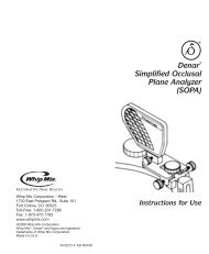
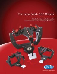
INTRODUCTIONThe WHIP MIX <strong>Articulator</strong> and “QUICKMOUNT” Face-Bow are designed to enable the user to quickly and easilymount casts of a patient’s dentition on a mechanical device that will reproduce their natural relationship andmovements with an acceptable degree of accuracy. The simplicity and speed with which the necessary registrationsare obtained and transferred to the WHIP MIX <strong>Articulator</strong> enable the operator to accomplish corrective andrestorative dentistry with much greater precision than has ever before been possible without the use ofexpensive equipment and time consuming techniques.For those already using a fully adjustable instrument, a WHIP MIX <strong>Articulator</strong> serves as an excellent auxiliaryinstrument for diagnostic and patient-education purposes, as well as for constructing the clutches andrecording devices needed to secure the proper recordings for setting the more complex instrument. Beingarcon type instruments, WHIP MIX <strong>Articulator</strong>s are ideal for the study of occlusion and the movements of thetempromandibular joint. With the condyle located on the lower frame and the guidance on the upper frame(arcon design), WHIP MIX semi-adjustable articulators have become the preferred choice of many teachinginstitutions. Advancing to a fully adjustable articulator becomes a much easier process after initial trainingon an arcon semi-adjustable articulator.<strong>2000</strong> Series <strong>Articulator</strong>s feature the same sturdy construction and reliability which have been demonstratedsuccessfully by other WHIP MIX <strong>Articulator</strong>s. In addition, the following innovative and useful features havebeen incorporated.• Ergonomic design• The successful concepts of a curved eminentia and immediateside shift capability• An easily positioned centric latch which provides a quick way to returnto centric position• A permanent intercondylar width of 110 mm — which is the same as theM setting found on other WHIP MIX <strong>Articulator</strong>s• Bilateral elastics function to hold the upper and lower members of thearticulator together during excursive movement if securedThe WHIP MIX Model 2240 and 2340 <strong>Articulator</strong>s are modified with the “ACCUMOUNT” Mounting System.This makes it possible to interchange mounted casts between any Model 2240 and 2340 <strong>Articulator</strong>without loss of accuracy.Just as with other models in the WHIP MIX family of articulators, a variety of accessories are available.Each <strong>2000</strong> Series <strong>Articulator</strong> is packaged with the following items:1 – Instruction Manual1 – Serial Number Card2 – #8580 Metal Mounting Plate, Set of 21 – Hex Driver5
OBTAINING FACE-BOW REGISTRATIONFig. 1Items needed for a Face-Bow Registration:Face-bow including nasion relator and face-bow fork(bite fork)Elastomeric registration materialAdhesive for elastomericI. Preparing Face-BowFig. 2Clean and properly disinfect the plastic ear pieces beforeeach use. If replacing them, make sure that the hole on theflat side of each is above the side arm and the plastic isseated until it touches the shoulder of the ear bow arm.Fig. 3A rubber-band may be easily positioned on the face-bowto aid in its manipulation.Note the ability of the nasion relator assembly to moveleft and right along the cross bar and the face-bowcaliper design allowing the side arms to move equaldistances during the opening and closing motions.Fig. 4Center the nasion relator assembly on the cross bar ofthe face-bow.6
Fig. 5Loosen the #8604 thumb screw on top of theface-bow. If using the metal face-bow, loosen thethree #8604 thumb screws.Fig. 6Loosen the #8640 thumb screw.Fig. 7Loosen the #8643 thumb screw.II. Preparing Face-Bow ForkFig. 8Elastomeric registration material may be used as a biteregistration medium for the bite fork.Make sure the bite fork has been properly sterilized.7
Fig. 9Apply elastomeric adhesive uniformly over the top surfaceof the bite fork.Fig. 10Apply elastomeric registration material to the top surfaceof the bite fork.Fig. 11Position the bite fork so that the midline of the bite forkaligns with the facial midline and support the fork until thematerial is set.The record should make a shallow registration of themaxillary cusp tips, and not perforate through to thebite fork.Fig. 12Inspect the registration for any soft tissue or deepocclusal registrations. It is only necessary to record themaxillary cusp tips, all else should be trimmed awayusing a sharp Bard-Parker blade.8
III. Positioning Face-Bow on the PatientFig. 13Before attempting to place the face-bow onto the bite fork,it is suggested that the operator explain the procedure tothe patient. Caution the patient that the plastic ear piecesin the auditory canal will greatly amplify noises duringthe procedure.Fig. 14Support the bite fork underneath by having the patient biteon cotton rolls. Some clinicians prefer to have the patientbite on the bite fork itself after registration material hasbeen placed on both sides.Fig. 15A finger cot placed over each ear piece will help facilitateproper disinfection of the face-bow.Remember, a rubber-band correctly placed will aidface-bow manipulation.Fig. 16With the bite fork positioned in the patient’s mouth, startthe toggle onto the bite fork shaft while the patient holdsthe side arms close to the ears.Note: Make sure the horizontal cross bar is above thebite fork shaft.9
Fig. 17Instruct the patient to place each ear piece into theexternal auditory meatus and hold in place with a firmforward pressure.Fig. 18Center the plastic nose piece on the patient’s nasion andexert firm pressure on the nose piece shaft while tighteningthe thumb screw of the nasion relator assembly. Thispressure will help to firmly seat the ear pieces into theexternal auditory meatus.Fig. 19Tighten the #8604 thumb screw on top of the face-bow.Fig. 20Push the #8642 toggle back on the fork shaft until it isnear, but not touching the lips.10
Fig. 21To prevent torquing of the face-bow and discomfort to thepatient, support the fork and the horizontal bar with onehand and tighten the #8640 thumb screw.Fig. 22Next, tighten the #8643 thumb screw on the vertical barwhile supporting the face bow, again taking care notto tilt the face-bow.Fig. 23The completed face-bow transfer.IV. Removing Face-Bow from the PatientFig. 24Loosen the #8604 thumb screw and slide the nasionrelator away from patient’s nose.11
Fig. 25Have the patient hold both arms of the face-bow andloosen the center thumb screw on top of the face-bow.Fig. 26The entire face-bow assembly is removed by advising thepatient to pull the ear pieces out of their ears while helpingto remove the bite fork from the mouth. Now is a convenienttime to make the interocclusal records necessary to mountthe mandibular cast and set the condylar guidance ofthe articulator.V. Obtaining Interocclusal RecordsThere are several materials available that may beused to make interocclusal records. There are alsodifferent techniques and philosophies for makingthese records. The material selected shouldcomplement the particular technique used. Thetechnique suggested in this manual is one methodand <strong>Whip</strong> <strong>Mix</strong> does not imply that this is the onlycorrect technique.The following interocclusal records (check bites)should be utilized to relate the mandibular cast tothe maxillary mounting and to program the condylarguidance of the articulator:• Centric Relation and/or Maximum Intercuspation• Right Lateral• Left Lateral• Protrusive (optional)12
Centric Relation RecordFig. 27Many clinicians prefer to use an anterior deprogrammingdevice such as a leaf gauge to help the patient achieve acentric relation position.Fig. 28Place the leaf gauge between maxillary and mandibularincisors. Instruct the patient to protrude and then retrudethe mandible while closing on the leaf gauge.Fig. 29Additional leaves are required if posterior contacts arepresent. Ideal disocclusion is 0.5 mm in posterior.Instruct the patient to move his mandible forward, back,and squeeze. This cycle should be repeated once a minutefor a total of ten minutes. The patient should be instructedto bite with only enough force to hold the leaf gaugein position.Fig. 30During the ten minute period verify that posteriordisocclusion is maintained. Add leaves as necessary.13
Fig. 31Usually after the ten minute period, a centric relation recordcan be made. The teeth are dried with cotton gauze.Note: Do not allow the patient to occlude while theleaf gauge is not in position.Fig. 32Inject elastomeric registration material onto themandibular occlusal surfaces.Fig. 33Place leaf gauge into position and instruct the patientto close into registration material. The patient is nowinstructed to protrude, retrude, squeeze together, andhold until the material is set.Fig. 34Remove and examine the centric relation record for:a. The presence of adequate cuspal indents.b. The absence of perforations through the material.14
Lateral Interocclusal RecordsFig. 35Manipulate the mandible into centric relation. Injectelastomeric registration material onto the mandibularocclusal surfaces. Instruct the patient, while open, toslowly move the jaw toward his right shoulder.Fig. 36After moving 4–6 mm laterally, instruct the patient toclose into the elastomeric until “cuspal indents” havebeen created.Maintain this position until the registration material is set.The clinician may find it useful to support the mandibleduring this time.Fig. 37Remove and examine the right lateral record for:a. The presence of adequate cuspal indents.b. The absence of perforation and/or soft tissue contact.Repeat this procedure for the left lateral check record,having the patient move his or her jaw toward his or herleft shoulder.15
DIRECT MOUNTING THE MAXILLARY CASTON <strong>2000</strong> SERIES ARTICULATORSI. Preparing the <strong>Articulator</strong> forMounting CastsFig. 38The following items are needed for mounting casts ona <strong>2000</strong> Series <strong>Articulator</strong>:Face-Bow Registrationlnterocclusal RecordsMaxillary and Mandibular Casts2 – Clean QuickMount Plates2 – Metal Mounting DisksMounting StoneSpatulaGraduated CylinderRubber BowlSticky WaxRigid WirePlaster KnifeFig. 39Set the centric latch in the “open” position.Fig. 40Detach the bilateral elastics from the lower frame.16
Fig. 41Loosen the #8511 incisal guide pin screw and removethe incisal guide pin.Fig. 42Set each condylar guide to the “FB” (Face-Bow)marking on the condylar inclination scale in preparationfor attaching the face-bow assembly to the upper frameof the articulator.Fig. 43The Model 2340 <strong>Articulator</strong>’s condylar guide should beset to 30° on the condylar inclination scale in preparationfor attaching the face-bow assembly to the upper frameof the articulator.Fig. 44Firmly tighten each Clamp Screw. This may beaccomplished by using the black thumb screws orthe hex driver.17
Fig. 45The immediate side shift guide settings are irrelevant at thispoint. However, it is advisable to set them to the “0” mark.Fig. 46On the Model 2340 <strong>Articulator</strong>, the progressive side shiftshould be set to the “0” mark.Fig. 47Place a metal mounting disk into each QuickMountMagnetic Plate.Fig. 48Attach QuickMount Magnetic Plates to the upper andlower frames of the articulator. The articulator is nowready to have the face-bow secured to its upper frame.18
II. Placing a Direct Mounting Face-Bowon the <strong>Articulator</strong>Fig. 49Slide the plastic nasion relator assembly to the side of thehorizontal crossbar of the face-bow if this has not alreadybeen done.Fig. 50Loosen the thumb screw on the top of the face-bow.Note: A rubber-band properly positioned aidsin manipulation.Fig. 51Guide the face-bow beneath the upper frame of thearticulator. The ear pieces should be even with the brassmounting pin.Fig. 52Position the brass mounting pin located on the outer flangeof the left condylar guide assembly into the hole on themedial side of the left plastic ear piece of the face-bow.While holding the left side of the face-bow in place, guidethe right brass mounting pin into the hole in the rightface-bow ear piece.19
Fig. 53Allow the anterior end of the upper frame of the articulatorto rest on the horizontal cross bar of the face-bow.Fig. 54Securely tighten the thumb screw on top of the face-bow.Note that the rubber-band maintains the ear piecesagainst the brass mounting pins with a slight pressurewhich helps facilitate stable placement of the face-bowon the articulator.Fig. 55Because the guidance of this instrument is part of theupper frame and the face-bow is, in effect, one piecewith this frame, the face-bow fork is in fixed relation tothe upper frame.Fig. 56The face-bow only relates to the upper member and not tothe lower member of the articulator. The relationship of theface-bow to the lower member is of no consequence at thispoint and the lower member will only serve as a convenientsupport during the mounting of the maxillary cast.20
Fig. 57Engage the centric latch for added stability.Fig. 58The Face-Bow Fork Support is a convenient accessory usedto support the bite fork during the mounting of the uppercast. The face-bow fork support attaches to the lower framein place of the lower mounting plate. Its cross arm is raisedto gently contact the under-surface of the face-bow fork toprevent flexing of the fork. (The 28706 is shown here.)III. Mounting the Maxillary Cast witha Direct Mounting Face-BowFig. 59Indices should be placed in cast if it will need to berecovered and replaced at any time, otherwise retentiveundercuts should be placed in the base.Fig. 60Soak the maxillary cast in clean slurry water.21
Fig. 61Seat the maxillary cast in the face-bow registration andmake sure it is stable with no rocking. The cast will needadditional trimming if the upper frame will not close so thatthe front end of the upper frame contacts the face-bowcross bar.Fig. 62<strong>Whip</strong> <strong>Mix</strong> MOUNTING STONE is ideal for mounting castsbecause it is formulated to have a short working time, greatstacking ability and extremely low setting expansion.Lift the upper frame of the articulator and apply mountingstone to the base of the cast and the mounting plate.An inaccurate mounting will result if the bite fork flexesduring mounting.Fig. 63Close the upper frame to contact the cross bar, bringing themounting stone on the two surfaces together. Do not usetoo thick a mix of mounting stone or attempt to apply forcewhen the stone has already begun to set. Hold the upperframe in position until the mounting stone has set.Fig. 64It is not necessary that the mounting stone be smoothand all voids filled with the first mix. Many cliniciansprefer to utilize a second mix to fill the voids after thefirst mix has set.22
INDIRECT MOUNTING THE MAXILLARY CASTFig. 65<strong>Whip</strong> <strong>Mix</strong> Indirect Mounting Face-Bows combine theface-bow registration technique of the traditional“QUICKMOUNT” Face-Bow with the many advantagesof indirect mounting. The indirect mounting procedureoffers the user more access, increased stability, greaterease of use, and optimum instrument efficiency.Incorporating the indirect mounting technique does notrequire dramatic technique changes. The face-bowregistration is taken on the patient utilizing the sametechnique as with the original <strong>Whip</strong> <strong>Mix</strong> “QUICKMOUNT”Face-Bow. Once the registration is obtained, the TransferAssembly is removed from the face-bow and positionedonto the lower frame of the articulator.Fig. 66All <strong>Whip</strong> <strong>Mix</strong> “QUICKMOUNT” Face-Bows can be modifiedto have indirect mounting capability.The conversion package includes:1 – Transfer Base Assembly1 – Cross Bar1 – Transfer AssemblyI. Preparing the Face-Bow and <strong>Articulator</strong>for Mounting CastsFig. 67Unscrew the #8604 Locking Screw on the cross bar torelease the transfer assembly which holds the biteregistration from the face-bow.23
Fig. 68Position the #8686 Support Bar onto the top of theTransfer Assembly and secure in place with the same#8604 Locking Screw.Remove the upper frame of the articulator from the lowerframe and then remove the incisal guide pin.Fig. 69Place the transfer base assembly on the lower member ofthe articulator and secure it using the magnetic face-bowfork support.Set the condylar inclination to the “FB” marking on eachcondylar inclination scale for articulators with immediateside shift. Set the condylar inclination to 30° for modelswith progressive side shift. Next, set the immediate orprogressive side shift guides to “0”.II. Placing the Face-Bow TransferAssembly on the <strong>Articulator</strong>Fig. 70Insert the vertical rod of the transfer assembly into thetransfer base and lower it until the bottom of the vertical rodcontacts the transfer base. Tighten the #9184 Clamp Screwso that the vertical rod fits securely in the Transfer Base.Fig. 71Place the upper frame of the articulator onto the lowerframe so the front of the upper frame now rests on the#8686 Support Bar and place a QuickMount MagneticPlate on the upper frame.24
Fig. 72Raise the face-bow fork support until it touches the undersurfaceof the face-bow fork.Fig. 73Engage the centric latch or spring latch on the articulator tokeep the condyles in contact with the posterior and superiorwalls of the condylar guides.III. Mounting the Maxillary CastFig. 74Position the upper cast into the bite registration.Fig. 75Apply <strong>Whip</strong> <strong>Mix</strong> MOUNTING STONE to the upper mountingplate and the top of the upper cast and carefully hinge theupper frame so that it contacts the top of the #8686Support Bar.When the stone has set, remove the upper frame to allowremoval of the transfer assembly and transfer base.Replacethe incisal guide pin in the upper frame and re-attach tolower frame. Also, replace the mounting plate on the lowerframe and proceed with the mounting of the lower cast asdescribed in the <strong>Articulator</strong> Instruction Manual.25
MOUNTING THE MANDIBULAR CASTFig. 76Replace the incisal guide pin in the upper frame,rounded end down.Fig. 77The pin should be adjusted 3–5 mm above the zero mark(the dark line encircling the pin) to compensate for thethickness of the centric relation (CR) or maximumintercuspation (MI) registration used to mount themandibular cast.Fig. 78Make sure the centric latch is engaged.Fig. 79Set both immediate side shift guides to the “0” position.26
Fig 80If using the Model 2340 <strong>Articulator</strong>, set both progressiveside shift guides to the “0” position.Fig 81Reattach the bilateral elastics to the lower frame.Fig. 82Place the articulator upside down, resting on the incisalguide pin and the two clamp screws.Fig. 83Trim interocclusal records so that only the cusp tips areremaining and place the CR or MI interocclusal registrationon the maxillary cast. Make sure the record is completelyseated on the maxillary cast.Make sure that retention grooves or indices have been cutinto the base of the mandibular cast.27
Fig. 84Position the mandibular cast on the CR or Ml registration,verify cast is completely seated into the registration andcheck for stability. Secure three 3-inch sections of coathanger wire to maxillary and mandibular casts with stickywax or impression compound.Make sure the mandibular cast has been properly wettedprior to mounting.Fig. 85Hinge the lower frame into an open position and applymounting stone to the base of lower model and the lowermounting plate.Fig. 86Hinge the lower frame closed until the incisal guide pinmeets the incisal guide block. Make sure the condylarelements are seated flush against the posterior andsuperior walls of the condylar guides. Carefully hold thearticulator in this position until the mounting stone has set.28
Fig. 87Prepare a second mix to fill any voids so that anaesthetic product results. Remove the stiff wire andinterocclusal records.Fig. 88Finally, loosen the incisal guide pin screw and lower the pinuntil the maxillary and mandibular casts contact. Retightenthe incisal guide pin screw and make sure the incisal guidepin is positioned in the center of the incisal guide table.29
SETTING THE CONDYLAR GUIDANCE OF THE ARTICULATORUSING LATERAL INTEROCCLUSAL RECORDSFig. 89Release the centric latch.Fig. 90Detach the bilateral elastics from the lower frame.Fig. 91Set both condylar guides to the 0º setting indicated on thecondylar inclination scale – firmly tighten the right condylarguide locking screw and lightly secure the left condylarguide locking screw.Fig. 92Set both immediate side shift guides to their mostopen position.30
Fig. 93If using the Model 2340 <strong>Articulator</strong>, set the progressive sideshift guides to their most open position.Fig. 94Loosen the incisal guide pin screw. Raise the incisal guidepin to prevent any interference and retighten the screw.Fig. 95With the upper frame and its cast inverted, carefully seatthe right lateral excursion interocclusal records on theupper cast.Fig. 96Holding the upper frame in one hand and the lower framein the other, place the right working condylar element in theright condylar guide. Make sure that the right condyle isseated “flush” against the rear wall. Gently seat the lowercast into the right lateral record and lightly hold thearticulator and casts in position on the right side.31
Fig. 97Notice that the left condylar element has moved away fromboth the superior and posterior surfaces of the condylarguide and toward the medial wall.Fig. 98To set the inclination of the left condylar guide, carefullyloosen its locking screw and rotate the guide until thesuperior wall touches the condyle element.It is advisable when making these adjustments that thecontact between the condyle and the superior wall shouldalso be judged by sight, rather than depending solely onthe sense of touch. This helps to make certain that thecasts are not forced out of position.Fig. 99Tighten the condylar guide locking screw to clamp theguide in position. DO NOT USE EXCESSIVE PRESSUREwhen tightening the locking screw.Fig. 100To set the left immediate side shift, loosen the left sideshift clamp screw and slide the left side shift guide untilit touches the side of the condyle element.32
Fig. 101If using the Model 2340 <strong>Articulator</strong>, loosen the left side shiftguide holding screw and move the side shift guide until ittouches the side of the condyle element.Fig. 102Retighten the left side shift clamp screw and then returnthe articulator to its upright position.Fig. 103Record the amount of condylar inclination andimmediate side shift found on the left side on aPatient Registration Card.33
Fig. 104The right condylar guidance is adjusted using the left lateralexcursion record and repeating the above procedure.34
SETTING THE CONDYLAR GUIDANCE OF THE ARTICULATORUSING PROTRUSIVE INTEROCCLUSAL RECORDSFig. 105Many clinicians wish to set the condylar inclination ofthe articulator with a protrusive record. To utilize theprotrusive record, first neutralize the condylar inclinationand immediate side shift settings. Place the protrusiverecord on the inverted upper frame of the articulator andgently seat the lower cast into the protrusive record.Fig. 106Both condylar elements will have moved away fromthe posterior and superior surfaces of their respectivecondylar guides.Fig. 107Using sight and touch, rotate the right condylar guide until itcontacts the condylar ball, then tighten the condylar lockingscrew. Record the reading and repeat the procedure on theleft side. The lateral records are then used to determine theimmediate side shift settings.Fig. 108The completed mounting on a Model 2240 <strong>Articulator</strong>.35
TECHNIQUE FOR FABRICATION OFA CUSTOM INCISAL GUIDE TABLEFig. 109To prevent possible abrasion of the stone casts duringmanipulation of the articulator, or to make a permanentdisocclusive record of a specific case, the natural incisalguidance may be recorded. This is done by adding a layerof self-curing resin to the plastic guide block and formingthe guidance path into the resin as it cures.Fig. 110The Dovetail Incisal Block is a convenient accessory whichhas been designed so that a custom acrylic guide maybe easily removed and can later be easily replaced. Itsdovetail sides and centering screw assure the user ofaccurate repositioning.Fig. 111Materials needed for fabrication of a custom incisalguide table.Fig. 112Raise the incisal guide pin 2–3 mm and release thecentric latch.36
Fig. 113Lubricate the rounded end of the incisal guide pin.Next, prepare the surface of the incisal guide table with1–2 drops of self-curing acrylic monomer.Fig. 114<strong>Mix</strong> enough acrylic to cover the incisal guide table toapproximately a 6 mm thickness.Fig. 115Once the acrylic is in a doughy state, place the acrylic ontothe incisal guide table.Fig. 116Close the articulator in centric position.37
Fig. 117Move the upper frame of the articulator to producea straight protrusive movement terminating in anend-to-end incisal relationship.Fig. 118From centric, move the upper member of the articulator togive a straight right lateral movement.Fig. 119Then, move the upper member of the articulator to give astraight left lateral movement.38
Fig. 120Move through all intermediate excursions between thelateral and protrusive positions. Repeat the excursivemovements until the acrylic has reached a firm stableconsistency. Allow the acrylic to polymerize and trimoff excess.Fig. 121Final custom incisal guide table.39
COMPLETE DENTURE TECHNIQUE(Shown on Model 2240 <strong>Articulator</strong>)I. Constructing Occlusion RimsFig. 122Having obtained a master cast, wax occlusion rims shouldbe formed on well-adapted record bases (base plates) forthe upper and lower arches. After examination of the upperrecord base in the patient’s mouth, adjust the base plate,if necessary.Contour the upper and lower occlusion rims, establishocclusal vertical dimension and plane of orientation.Fig. 123Create wedge-shaped V indices in the wax occlusion rims.II. Preparing the Face-Bow ForkFig. 124Apply elastomeric adhesive to a properly sterilizedbite fork.Note: Adhesive not mandatory when usingperforated bite fork.Fig. 125Some clinicians prefer to utilize a pronged bite fork.40
III. Preparing Face-Bow ArmamentariumFollow the same procedure as that outlined earlier onpages 6–7.IV. Positioning Face-BowFig. 126Extraorally, record the maxillary wax rim indices onto thebite fork using elastomeric. Make sure the mid-line of thepalate and the stem of the bite fork are properly aligned.Fig. 127Place bite fork/wax rim assembly into patient’s mouth.Fig. 128Position the face-bow onto the patient as described onpages 9-12.Fig. 129Tighten the thumb screw on top of the face-bow.41
Fig.130Tighten the thumb screw on the horizontal bar first. Next,tighten the thumb screw on the vertical bar.Fig. 131Once the face-bow record has been made, remove the waxrim and record base from the bite fork registration. Setaside the face-bow assembly for later mounting.V. Obtaining Interocclusal RecordsFig. 132To make the jaw relation record, an elastomeric registrationmaterial or other appropriate record medium is placed ontothe V indices of the wax rim.Fig. 133The patient is guided into centric relation and is allowed toclose until the wax rims come into contact. The registrationmaterial is allowed to set and is then removed.42
VI. Preparing the <strong>Articulator</strong> forMounting CastsFig. 134Many operators prefer to replace the plastic incisal guideblock with an adjustable metal table, such as the #2460Adjustable Guide Table (shown).Fig. 135To install the adjustable guide table, remove the #8526FPlastic Incisal Guide from the articulator. Slide theadjustable table into the thumb screw slot in the lowerframe of the articulator and tighten the thumb screw.Fig. 136Adjust the position of the adjustable guide table until thechiseled end of the incisal guide pin lies directly over thescribed line on the guide table.Note: Guide pin must be set at “0” on upper member.VII. Mounting the Maxillary CastFig. 137The indirect technique of mounting the maxillary cast willbe demonstrated. However, the direct mounting techniquemay also be used to mount the maxillary edentulous cast.The transfer assembly has been removed from the facebowand the support bar is placed into position.43
Fig. 138The QUICKMOUNT transfer base has been placed ontothe lower member of the articulator and is held in positionby the QUICKMOUNT cast support. The transfer assemblyis inserted into the transfer base and the clamp issecurely tightened.Fig. 139The QUICKMOUNT cast support is adjusted until it lightlymakes contact with the bottom of the bite fork.Fig. 140The cast is placed into the occlusion rim, which is thenseated into the registration on the bite fork. The assemblyis now completed and ready for the addition of <strong>Whip</strong> <strong>Mix</strong>MOUNTING STONE.Fig. 141The completed mounted maxillary cast. The transferassembly and transfer base may be removed and theincisal guide pin replaced.44
VIII. Mounting the Mandibular CastFig. 142Place the jaw relation records between the wax occlusionrims. Be certain the casts or record bases are not in contactwith one another. Casts may be secured in this position byusing rigid wire and sticky wax.Fig. 143The mounted maxillary and the affixed mandibular castscan now be placed on the articulator. The casts andarticulator are inverted and <strong>Whip</strong> <strong>Mix</strong> MOUNTING STONEis added.Fig. 144The mounting is complete. Additional jaw relationrecords can verify its accuracy. Accurate fit of theverification records into the V-shaped indices willdenote a precise mounting.IX. Setting the Adjustable IncisalGuide TableAfter the anterior denture teeth are positioned, theadjustable guide table may be set.Fig. 145Release the latch on the articulator. Loosen the #2472Indicator Clamp Knob of the incisal guide table andbring the anterior teeth into edge-to-edge contact.45
Fig. 146Adjust the inclination of the guide table until it contacts theincisal pin, then retighten the #2472 Indicator Clamp Knob.Fig. 147Move the teeth into a left lateral relation.Fig. 148Loosen the #2466 Clamping Knob and raise the right wingof the table until it touches the chisel end of the guide pin.Tighten the clamping knob to secure this position andrepeat the same operation for the left wing with the teethin a right lateral position.X. Obtaining Protrusive RecordFig. 149The aesthetic try-in appointment affords the clinician theability to verify tooth setup and obtain a well-indexedprotrusive record. The record should be created at anextended protrusive position to allow for bilateralcondylar movement.46
Fig. 150Set condylar inclinations on the articulator as describedpreviously on pages 36–41.XI. Fabricating a Remount IndexFig. 151After denture processing, replace the maxillarydenture and cast onto the indexed mounting. Replacethe mounting, cast, and denture onto the articulator.Attach the QUICKMOUNT remount jig to the lower frame.Fig. 152Add sufficient stone to the remount jig to index only thecusp tips of the denture teeth.Fig. 153The completed remount index.47
XII. Remounting CastsFig. 154After the dentures have been polished, the maxillarydenture can be mounted to the articulator in anticipation ofa clinical remount to evaluate the denture occlusion.Obtain remount casts. Using the remount index, mount themaxillary denture and remount cast to the articulator.Fig. 155During the clinical placement of the dentures followingadjustment of tissue surfaces, new centric relation recordsare made and used to mount the mandibular denture andremount cast. The denture occlusion may be evaluated andadjusted as needed.XIII. Completed DenturesFig. 156The patient and her completed dentures.48
WHIP MIX RECORDING SYSTEMSFig. 157For the clinician who desires a recording system, <strong>Whip</strong> <strong>Mix</strong>offers the #8450 QUICK SET RECORDER.The #8450 QUICK SET recording systems offers a timesaving method for recording the protrusive condylar pathand measuring the amount of immediate side shift. The#8450 QUICK SET RECORDER provides this informationfrom an approximate hinge axis location.Listed below are other potential uses of the#8450 QUICK SET RECORDER. 11. Measurement of the timing or absence of a click duringsplint therapy.2. Comparison of click patterns in vertical opening andlateral and protrusive excursions.3. Setting an articulator for analysis or treatment.4. Comparison of eminence angles before side-to-siderestorative dentistry.5. Estimates of eminence angles before surgicaleminectomies.6. Measurement of condylar movement after TMJ surgery.1 Bates, Robert E., Welsch, Boyd B., and Stewart, Carol M., “TemporoMandibular Joint Disk Position as Determined by a Simple Recorder,” Journal ofProsthetic Dentistry, Vol. 56, No. 2, pp. 221-224, 1986.49
TRANSFER OF CASTS TO ANOTHER ARTICULATORIt is often desirable to remove the casts from the <strong>Whip</strong> <strong>Mix</strong> <strong>Articulator</strong> on which they wereoriginally mounted and to place them on another <strong>Whip</strong> <strong>Mix</strong> instrument. This is a greatconvenience when the casts are to be forwarded to an out-of-town laboratory.The only change from the customary procedure for mounting is the method of mountingthe mandibular cast. The “split-cast” mounting technique using notches is followed, OR,the cast is attached to its mounting plate so that it can be easily removed later withoutdanger of damage.The following are sent to the laboratory:• The mounted maxillary cast• The mandibular cast (removed from its mounting)• A duplicate patient registration card• The interocclusal centric registration used in the original mounting• The plastic incisal guide table on which the incisalguidance has been recordedThe technician places the mounted maxillary cast on the articulator. Using the centricregistration, the mandibular cast is then mounted to the lower frame of the second articulator.The incisal guide table is positioned, and the incisal pin is adjusted to the correct verticalheight. The condylar guidance is set from the notations on the patient’s record card, andthe transfer is complete.If the “split technique” was used on the first mounting of the mandibular cast, this originalmounting should be saved. When the casts are returned, they can be quickly replacedon the original articulator.50
INTERCHANGEABILITY WITH THE MODEL 2240AND 2340 ARTICULATORFig. 158The Model 2240 and 2340 <strong>Articulator</strong>s incorporate thebasic design of the Model 2200 and are modified with the“ACCUMOUNT” Mounting System. The “ACCUMOUNT”System makes it possible for the dental practitioner andthe dental laboratory to interchange casts withoutexchanging articulators.Fig. 159During manufacture, each Model 2240 or 2340 <strong>Articulator</strong>has a special table firmly and precisely attached to thelower frame using a special fixture and low-fusing alloy.Fig. 160The relationship between the upper and lower mountingplate is checked to verify precise alignment. This assuresthat casts can be interchanged between any Model 2240<strong>Articulator</strong> or between Model 2340 <strong>Articulator</strong>s withoutloss of accuracy.Features and Advantages1. When clinicians and dental students use a dental laboratorythat has a Model 2240 or 2340 <strong>Articulator</strong>, casts need nolonger be mounted on an articulator when shipped to sucha laboratory.2. Clinicians can purchase fewer instruments whilemaintaining the same level of care for their patients.3. Instrument damage caused by shipping the articulator toand from the dental lab is eliminated.4. Precise alignment of the upper and lower frames ischecked at the factory prior to shipping.51
REMINDERS AND SUGGESTIONS1. When securing interocclusal records to be used in mounting casts and setting the articulator,never allow the teeth to penetrate the recording material (Impression compound, wax, gypsum,impression paste, etc.) too deeply. They should never contact the opposing teeth, the metalface-bow fork, or any firm material that may be used as a carrying tray or handle. Any recordshowing evidence of penetration should be discarded and remade.2. The more stable a recording material is, the more it will resist distortion during its later use.Any such material should be in a very soft state, however, during the initial recording procedure.3. The following technique may be used to secure interocclusal records of partially edentulouspatients.If natural dentition opposes the edentulous space, the partial occlusion rim is built up tonearly touch the opposing teeth. Zinc oxide and eugenol impression paste is then addedto the surface of the occlusion rim of sufficient depth to register the tips of the opposingteeth when brought into the desired relationship.When the opposing spaces are both edentulous, one occlusion rim is built up in the customarymanner to near the occlusal plane, while the opposing rim is built to near this plane withsmall cones of hard wax (or plastic) to indicate the registration in the impression paste.When absence of teeth makes it necessary to obtain interocclusal records on partial occlusionrims, these records must be made with the supporting soft tissue in as near a static conditionas is possible; some combination of these ideas can be planned to accomplish this withacceptable accuracy.4. With casts of unusually thin vertical dimensions, which would necessitate the use of a greatbulk of mounting stone, it is suggested that the mounting plate be built up to near the correctthickness with a mix of mounting stone, This mix should be allowed to set for twenty minutesor longer before the actual mounting procedure is performed.5. Mounted casts that have been attached to their mounting plates on one 2200 or DB<strong>2000</strong>instrument cannot be transferred to another. Should it be necessary to remove the mountingsfrom an articulator before completion of the case, it is advisable to clearly mark the serialnumber of the instrument on the casts so they may be returned to the correct instrumentwhen desired.6. A thin film of lubricant (<strong>Whip</strong> <strong>Mix</strong> LUBRIPLATE) applied occasionally to the surfaces uponwhich the condylar elements move will provide a smooth action of these parts.7. For Model 2240 and 2340 <strong>Articulator</strong>s, make a split cast mounting on the articulator beforemounting the first case. This will be used for reference purposes should the articulator everbe dropped or mishandled. If the split cast mounting ever shows any discrepancy, returnthe articulator to the dealer for factory recalibration at a nominal charge.52
MAINTENANCEThe <strong>Whip</strong> <strong>Mix</strong> <strong>Articulator</strong> is a sturdily constructed instrument that will provide many years of servicewith reasonable care. Both the upper and lower frames are made of cast aluminum. All aluminumparts are anodized to prevent corrosion or staining. The condyle elements are made of stainlesssteel and the condylar guide assemblies are made of chrome-plated silicon bronze.• Avoid getting wax or stone in the screw holes which may damage the threads.• Tighten screws snugly, but not too tightly. Overtightening the retaining screwscan strip the threads.• It is a good idea to use a carrying case when the articulator is transported.Dropping the articulator may result in bent or broken parts which may affect thearticulator’s ability to accurately reproduce a patient’s mandibular movements.• Failing to remove excess stone, or not keeping the articulator clean, may resultin corrosion of articulator surfaces.• A thin film of lubricant (<strong>Whip</strong> <strong>Mix</strong> LUBRIPLATE) applied to the surfaces uponwhich the condylar elements move will provide a smooth action of these parts.• Every couple of months, place a drop or two of hand piece oil inside the #2019Latch Assembly to insure optimum movement.• Apply silicone spray to articulator frame to prevent plaster or stone fromsticking to surfaces.53
<strong>2000</strong> SERIES ARTICULATOR PARTS LISTS2524222326212720281918171316153112MODEL 2240ARTICULATOR14101129# PART# QTY. DESCRIPTION1 MA2014 1 HEX WRENCH2 MA8614 1 HEX DRIVER3 MA8543 1 FOOT PAD4 MA8527 1 INCISAL BLOCK SCREW5 MA8548 2 SET SCREW6 MA8508 2 MOUNTING PLATE KNOB7 MA8546 2 FIBER WASHER8 MA2038 1 BASE9 MA8504 2 CONDYLAR ELEMENT10 MA2019 1 LATCH ASSEMBLY11 MA8545 2 STEEL WASHER12 MA2242 1 MOUNTING PLATE SCREW13 MA8507 1 MOUNTING PLATE SCREW14 MA2030 2 PIN15 MA2016 2 STRAP16 MA2026 2 BUTTON HEAD SCREW17 MA8309 2 SIDE SHIFT CLAMP SCREW18 MA8306 1 SIDE SHIFT GUIDE (LEFT)MA8305 1 SIDE SHIFT GUIDE (RIGHT)19 MA8519 2 FACE-BOW MOUNTING PIN20 MA2204 1 FOSSA (LEFT)MA2203 1 FOSSA (RIGHT)21 MA2018 1 CENTERING PIN22 ME4415 1 SET SCREW23 MA8803 2 CONDYLAR GUIDE CLAMP24 MA8804 2 CLAMP WASHER25 MA2041 2 CLAMP SCREW26 MA8810 2 MOUNTING PLATE PIN27 MA2001 1 TOP PLATE28 MA8511 1 INCISAL PIN SCREW29 MA2201 1 INCISAL PIN30 MA8526F 1 INCISAL BLOCK31 MA8513 2 SCREW32 MA8342 1 MOUNTING TABLE33 MA8509 1 MOUNTING PLATE PIN34 MA2037 1 UPRIGHT35 MA8505 2 LEG36 MA8506 2 LEG SCREW37 MA2042 2 ARTICULATOR FOOTNOT SHOWNMA8580 2 MOUNTING PLATEMA8580B 2 MOUNTING PLATE93483536 7376123233530354354
21201615181719222314131224911MODEL 2340ARTICULATOR271025# PART# QTY. DESCRlPTlON1 MA8614 1 HEX DRIVER2 MA8543 1 FOOT PAD3 MA8527 1 INCISAL BLOCK SCREW4 MA8548 2 SET SCREW5 MA8508 2 MOUNTING PLATE KN0B6 MA8546 2 FIBER WASHER7 MA2038 1 BASE8 MA8504 2 CONDYLAR ELEMENT9 MA8513 2 CLAMP SCREW10 MA8545 2 STEEL WASHER11 MA2242 1 MOUNTING PLATE SCREW12 MA8507 1 MOUNTING PLATE SCREW13 MA8523 1 SIDE SHIFT GUIDE (RIGHT)MA8524 1 SIDE SHIFT GUIDE (LEFT)14 MA2321 1 FOSSA (RIGHT)MA2322 1 FOSSA (LEFT)15 MA8547 2 FIBER WASHER16 MA8520A 2 SIDE SHIFT KNOB17 MA2018 1 CENTERING PIN18 ME4415 1 SET SCREW19 MA8803 2 CONDYLAR GUIDE CLAMP20 MA8804 2 CLAMP WASHER21 MA2041 2 CLAMP SCREW22 MA8810 2 MOUNTING PLATE PIN23 MA2001 1 TOP PLATE24 MA8511 1 INCISAL PIN SCREW25 MA2201 1 INCISAL PIN26 MA8526F 1 INCISAL BLOCK27 MA2019 1 SPRING LATCH ASSEMBLY28 MA8342 1 MOUNTING TABLE29 MA8509 2 MOUNTING PLATE PIN30 MA8505 2 LEG31 MA8506 2 LEG SCREW32 MA2037 1 UPRIGHT33 MA2042 2 ARTICULATOR FOOTNOT SHOWNMA8580 2 MOUNTING PLATEMA8580B 2 MOUNTING PLATE832730333165128292634 255
WHIP MIX FACE-BOW PARTS LISTSMODEL 8645FACE-BOWFOR DIRECT MOUNTING# PART# QTY. DESCRlPTlON1 MA8640 1 THUMB SCREW2 MA8643 1 THUMB SCREW3 MA2424 1 WASHER NYLON4 MA8617 1 SCREW5 MA8644 1 HORIZONTAL CLAMP ROD6 MA8608 1 SLIDE BAR ASSEMBLY7 MA8601 1 FACE-BOW (RIGHT)8 MA8603R 1 EAR PIECE (RIGHT)9 MA8603L 1 EAR PIECE (LEFT)10 MA8602 1 FACE-BOW (LEFT)11 MA8604 3 LOCKING SCREW12 MA8607 1 NOSE BLOCK13 MA8622 1 SCREW FOR UPRIGHT POST14 MA8606 1 NOSE PIECE SHAFT15 MA8605 1 UPRIGHT POST16 MA8609 1 BITE FORK17 MA8619 2 RETAINING RING18 MA8641 1 TOGGLE19 MA8616 1 LOCK WASHER20 MA8642 1 TOGGLENOT MA8549 PKG. OF 6 RUBBERSHOWNBANDS56
MODEL 9600FACE-BOWFOR DIRECT MOUNTING# PART# QTY. DESCRlPTlON1 MA8640 1 THUMB SCREW2 MA8643 1 THUMB SCREW3 MA8617 1 SCREW4 MA2424 1 WASHER NYLON5 MA8644 1 HORIZONTAL CLAMP ROD6 MA8609 1 BITE FORK7 MA8608 1 SLIDE BAR ASSEMBLY8 MA9605 1 NUT9 MA9601-1 1 FACE-BOW (RIGHT)10 MA8603R 1 EAR PIECE (RIGHT)11 MA8603L 1 EAR PIECE (LEFT)12 MA9606A 3 SCREW13 MA9602-1 1 FACE-BOW (LEFT)14 MA8607 1 NOSE BLOCK15 MA8622 1 SCREW FOR UPRIGHT POST16 MA8606 1 NOSE PIECE SHAFT17 MA8619 2 RETAINING RING18 MA8605 1 UPRIGHT POST19 MA8641 1 TOGGLE20 MA8616 1 LOCK WASHER21 MA8642 1 TOGGLE22 MA8603A 1 EAR PIECE SOFT SETNOT MA8549 PKG. OF 6 RUBBERSHOWNBANDS57
MODELS 9175/9185/9195FACE-BOWSFOR INDIRECT MOUNTINGWITH DB<strong>2000</strong>/2200/9000/9800ARTICULATORS# PART# QTY. DESCRlPTlON1 MA9180 1 SCREW, RD HEAD2 MA9183 1 CLAMP3 MA9182 1 FIXED CLAMP4 MA2424 1 WASHER NYLON5 MA9176 1 TRANSFER BASE6 MA8644 1 HORIZONTALCLAMP ROD7 MA8609 1 BITE FORK8 MA9177 1 VERTICAL ROD FOR#MA9175 FACE-BOWMA9187 1 VERTICAL ROD FOR#MA9185 FACE-BOWMA9196 1 VERTICAL ROD FOR#MA9195 FACE-BOW9 MA8686 1 SUPPORT BAR10 MA8679 1 CROSS BAR11 MA8601 1 FACE-BOW (RIGHT)12 MA8603R 1 EAR PIECE (RIGHT)13 MA8603L 1 EAR PIECE (LEFT)14 MA8604 4 LOCKING SCREW15 MA8602 1 FACE-BOW (LEFT)16 MA8622 1 SCREW FORUPRIGHT POST17 MA8607 1 NOSE BLOCK18 MA8606 1 NOSE PIECE SHAFT19 MA8605 1 UPRIGHT POST20 MA8619 3 RETAINING RING21 MA8641 1 TOGGLE CLAMP22 MA8616 1 LOCK WASHER23 MA8642 1 TOGGLE CLAMP24 MA8643 1 THUMB SCREW25 MA8640 1 THUMB SCREW26 MA9184 1 CLAMP SCREWNOT MA8549 PKG. OF 6 RUBBERSHOWNBANDS58
MODELS 9275/9285/9295FACE-BOWSFOR INDIRECT MOUNTINGWITH 2240/2340/8340ARTICULATORS(PLASTIC EAR BOW)# PART# QTY. DESCRlPTlON1 MA9180 1 SCREW, RD HEAD2 MA9183 1 CLAMP3 MA9182 1 FIXED CLAMP4 MA9176 1 TRANSFER BASE5 MA2424 1 WASHER NYLON6 MA8644 1 HORIZONTALCLAMP ROD7 MA8609 1 BITE FORK8 MA9610 1 CROSS BAR ASSEMBLY9 MA8604 1 LOCKING SCREW10 MA8606 1 NOSE PIECE SHAFT11 MA8607 1 NOSE BLOCK12 MA9608 4 WASHER NYLON13 MA9607 2 SCREW BUTTON HEAD14 MA9601-1 1 FACE-BOW (RIGHT)15 MA8903R 1 EAR PIECE (RIGHT)16 MA8603L 1 EAR PIECE (LEFT)17 MA9602-1 1 FACE-BOW (LEFT)18 MA9606A 1 SCREW19 MA9605 1 NUT20 MA8622 1 SCREW FORUPRIGHT POST21 MA8619 3 RETAINING RING22 MA8686 1 SUPPORT BAR23 MA8641 1 TOGGLE24 MA8616 1 LOCK WASHER25 MA8642 1 TOGGLE26 MA8643 1 THUMB SCREW27 MA9177 1 VERTICAL ROD FOR#MA9275 FACE-BOWMA9187 1 VERTICAL ROD FOR#MA9285 FACE-BOWMA9196 1 VERTICAL ROD FOR#MA9295 FACE-BOW28 MA8640 1 THUMB SCREW29 MA9184 1 CLAMP SCREW30 MA8603A 1 EAR PIECE SOFT SETNOT MA8549 PKG. OF 6 RUBBERSHOWNBANDS59
BIBLIOGRAPHYThe following bibliography gives more background on this instrument system.Bates, Robert E., Welsch, Boyd B., and Stewart, Carol M.:Temporo Mandibular Joint Disk Position as Determined by a Simple Recorder.J. Pros. Dent., Vol. 56 No. 2, 221-224, 1986.Cowan, Robert D., Sanchez, R.A., Chappell, R.P., Glaros, A.G., Hayden, W.J.:Verifying the Reliability of Interchanging Casts with Semi-Adjustable <strong>Articulator</strong>s.Inter. J. Pros. Dent., Vol. 4, No. 3, 260-264, 1989.Lee, Robert L.:Law Movements Engraved in Solid Plastic for <strong>Articulator</strong> Controls. Part 1,Recording Apparatus, J. Pros. Dent., 22:209, 1969.Lee, Robert L.:Jaw Movements Engraved in Solid Plastic for <strong>Articulator</strong> Controls. Part II,Transfer Apparatus, J. Pros. Dent., 22:513, 1969.Loos, Larry:Clinical Criteria Used to Select an <strong>Articulator</strong>, Compendium, Vol. XIV,No. 1, 80-82, 1993.Lundeen, Harry C., Wirth, Carl G.:Condylar Movement Patterns Engraved in Plastic Blocks. J. Pros. Dent.,30:866, 1973.Lundeen, H.C.:An Evaluation of Mandibular Border Movements: Their Character & Significance.J. Pros. Dent., 40:4424-452, 1978.Lupkiewicz, S.M., Ariet, M., Fujimoto, J., Gibbs, C.H., Lundeen, H.C., & Mahan, R.E.:Reproductibility of Border Movements, Part 1, 2 & 3. IADR Progr. & Abst. 57:No. 367 & 368, 1978.McCoy, R.B., Shyrock, E.F., & Lundeen, H.C.:A Method of Transferring Mandibular-Movement Data to Computer Storage.J. Pros. Dent., 36:510, 1976.Sokolow, Stanley M.:Interchangeable Quick-Mounted Study Models. J. Clinical Orthodontics,Vol. XX, No. 11:779-781, 1986.Welsch, Boyd B.:The Distribution of the Radius of the Curve Scribed During Protrusion.J. Pros. Dent., Vol. 51, No. 4:518, 1984.Special thanks to the Postdoctoral Prosthodontics Program at theUniversity of Texas Health Science Center at San Antonio.60
For additional information, contactour Technical Department at:<strong>Whip</strong> <strong>Mix</strong> Corporation361 Farmington Ave.P.O. Box 17183Louisville, KY USA 40217-0183502-637-1451800-626-5651Fax 502-634-4512www.whipmix.comMPL30121 6/03