NEETS Module 8, Chapter 1
NEETS Module 8, Chapter 1
NEETS Module 8, Chapter 1

You also want an ePaper? Increase the reach of your titles
YUMPU automatically turns print PDFs into web optimized ePapers that Google loves.
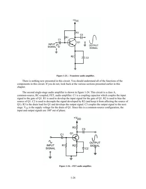
Figure 1-23.—Transistor audio amplifier.There is nothing new presented in this circuit. You should understand all of the functions of thecomponents in this circuit. If you do not, look back at the various sections presented earlier in thischapter.The second single-stage audio amplifier is shown in figure 1-24. This circuit is a class A,common-source, RC-coupled, FET, audio amplifier. C1 is a coupling capacitor which couples the inputsignal to the gate of Q1. R1 is used to develop the input signal for the gate of Q1. R2 is used to bias thesource of Q1. C2 is used to decouple the signal developed by R2 (and keep it from affecting the source ofQ1). R3 is the drain load for Q1 and develops the output signal. C3 couples the output signal to the nextstage. V DD is the supply voltage for the drain of Q1. Since this is a common-source configuration, theinput and output signals are 180º out of phase.Figure 1-24.—FET audio amplifier.1-26