Burnham V8 Series Instructions.pdf - Heating Help
Burnham V8 Series Instructions.pdf - Heating Help
Burnham V8 Series Instructions.pdf - Heating Help

You also want an ePaper? Increase the reach of your titles
YUMPU automatically turns print PDFs into web optimized ePapers that Google loves.
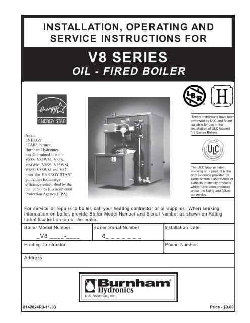
INSTALLATION, OPERATING ANDSERVICE INSTRUCTIONS FOROIL<strong>V8</strong>-SERIESFIREDBOILERAs anENERGYSTAR ® Partner,<strong>Burnham</strong> Hydronicshas determined that the<strong>V8</strong>3S, <strong>V8</strong>3WM, <strong>V8</strong>4S,<strong>V8</strong>4WM, <strong>V8</strong>5S, <strong>V8</strong>5WM,<strong>V8</strong>6S, <strong>V8</strong>6WM and <strong>V8</strong>7meet the ENERGY STAR ®guidelines for Energyefficiency established by theUnited States EnvironmentalProtection Agency (EPA).These instructions have beenreviewed by ULC and foundsuitable for use in theinstallation of ULC labeled<strong>V8</strong> <strong>Series</strong> Boilers.The ULC label or listedmarking on a product is theonly evidence provided byUnderwriters' Laboratories ofCanada to identify productswhich have been producedunder the listing and followupservice.For service or repairs to boiler, call your heating contractor or oil supplier. When seekinginformation on boiler, provide Boiler Model Number and Serial Number as shown on RatingLabel located on top of the boiler.Boiler<strong>Heating</strong>Model Number_ <strong>V8</strong>____-____ContractorBoilerSerial Number6_______Installation DatePhone NumberAddress8142824R3-11/031Price - $3.00
3DANGERorthisofvicinitytheinliquidsorvaporsflammableotherorgasolineuseorstoreDO NOTappliance.otheranyWARNINGpropertycausecanmaintenanceorservicealteration,adjustment,installation,ImproperpropertheininstructionsallfollowtoFailurelife.oflossorinjurypersonaldamage,instructions,allunderstandandReaddeath.orinjurypersonalcausecanorderprovidedarewhichmanualsmanufacturerscomponentincontainedthoseallincludingthisservicingormaintainingoperating,starting-up,installing,beforeappliancethewithnearpostedandconditionlegibleinliteratureandmanualthisKeepappliance.technician.serviceandownerbyreferenceforappliancetheFollowsafely.operatetoserviceandmaintenanceregularrequiresboilerThismanual.thisincontainedinstructionsexperienced,anbyonlyperformedbemustserviceandmaintenance,Installation,agency.serviceorinstallerknowledgeableandskilledpersonsonlyandcontractorscompetentbydesignedbeshouldsystemsheatingAllshouldsystemsheatinghydronicofinstallationandlayouttheinknowledgeableboiler.anyofinstallationattempttappingtheintoinstalledisvalvereliefpressureaunlesscompletenotisInstallationmanualthisofTrim SectionsandPipingSeesectionfrontofcornerlefttoponlocateddetails.forcorrectlyarecontrolsallthatseetocontractorinstallingtheofresponsibilitytheisItcompleted.isinstallationthewhenproperlyoperatingareandinstalledonboilerinstallnotDoflooring.combustibleoninstallationforsuitableisboilerThiscarpeting.controls.orboilerthealterorwithtampernotDoseason.heatingtheofstarttheatpreferably-yearaonceleastatfluewaysInspectbeshouldfluewaysboilersystem andventthechamber,combustiontheofinsideTheaccumulated.hasscaleorsootifcleanedtargetrearand/orlinerchambercombustiondamagenotdoboiler,thiscleaningWhenimmediately.replacedbemustinsulationchambercombustiondamaged,Ifwall.bemayasoryearaonceleastatcheckedbemustControlsandBurnerOilnecessitated.devices.safetyorcontrolsabsentorjumperedwithunitoperatenotDotosubjectbeenhasdeviceorcomponent,switch,control,anyifunitoperatenotDowater.containfueltheandcombustionofproductsconstruction,ofmaterialsApplianceand/oraldehydesoxides,nitrogenmonoxide,carbonmetals,heavysilica,alumina,whichandinjuryseriousordeathcausecanwhichsubstancesharmfulortoxicotherotheranddefectsbirthcancer,causetoCaliforniaofstatethetoknownareequipmentandrespiratorsclothing,safetyproperuseAlwaysharm.reproductiveappliance.thenearbyworkingorservicingwhen
4WARNINGpipeanyunscrewnotDopressure.highunderwaterhotverycontainsboilerThispositivelywithoutboilerthisofcomponentsanydisconnecttoattemptnorfittingsandclothingprotectivewearAlwayspressure.nohasandcooliswatertheassuringinjuries.scaldpreventtoboilerthisservicingorupstartinginstalling,whenequipmentandtemperaturethedeterminetogaugestemperatureandpressuretheonrelynotDowhenhotverybecomewhichcomponentscontainsboilerThisboiler.theofpressurecool.aretheyunlesscomponentsanytouchnotDooperating.isboilertheequippedisboilerthisIfinjury.scaldingofrisktheincreasetemperatureswaterHighmixingautomaticandregulatorflowasupply,waterdomesticforheatertanklessawithTrimandPipingSeepiping.heatertanklessinproperlyinstalledbemustvalvedetails.formanualthisofSectionssystem inventapprovedantoconnectedandventedproperlybemustapplianceThissystem.ventapprovedanofabsencethewithboileroperatenotDocondition.goodaretheresoinstalledbemustandoperationsafeforairfreshneedsboilerThisair.ventilationandcombustionadequateforprovisionscouldthatfumesnoxiousallowtonecessaryisfluechimneyunobstructedandA cleanthemaintainingtowardcontributewillandsafelyventtolifeoflossorinjurycauseefficiency.boiler'snotanddownshuttoboilerthecausemaywhichcontrolswithsuppliedisboilerThisheatingthepossibility,aispipesfrozentoduedamageIfservice.withoutre-startandsafeguardsappropriateorweather;coldinunattendedleftbenotsystem shouldisboilertheifdamagepreventsystem toheatingtheoninstalledbeshouldalarmsinoperative.crankcasegasoline,usenotDoonly.oilfuel2No.burntodesignedisboilerThisboiler.thisinpaperorgarbageburnNevergasoline.containingoilanyordrainings,fuelgaseousanytoconvertnotDocoal).wood,(i.e.fuelsolidanytoconvertnotDobeshouldetc.,scraps,woodpaper,rags,debris,flammableAllLP).gas,natural(i.e.hazards.fireoffreeandcleanareaboilertheKeeptimes.allatboilertheofclearkeptignoredifwhichhazardpotentialahavedoorswingburnerwithequippedboilersAllopeningBeforelife.oflossorinjurypersonaldamage,propertyseverecausecanburneroffiringaccidentalpreventtoboilertoswitchserviceoffturndoor,swingcompletelyfastenerdoorswingtightentosureBechamber.combustiontheoutsidecompleted.isservicewhenTABLE OF CONTENTS.I .re-Installation..........................................P 01 .IIIV .lectrical.............................................E 73I.I .Assembly....................BoilernockdownK 21 .XI .Piping...........................................ilO 44II.I .Assembly........................BoilerackagedP 02 .X .ystem Start-Up.................................S 64V.I .& Trim......................PipingBoileraterW 42 .IX .<strong>Instructions</strong>...& ServiceaintenanceM 45.V .& Trim......................Pipingteam BoilerS 92 .IIX .Cleaning...................................oilerB 85I.V .Piping...HeaterWater& IndirectanklessT 13 .IIIX .Shooting................................roubleT 06II.V .Piping......................Intake& AirentingV 43 .IVX .Parts.........................................epairR 16
TABLE 1A: DIMENSIONAL DATA (SEE FIGURES 1A THRU 1D)TABLE 1B: RATING DATABoilerModel No.**BoilerModelNo.GPHBurnerMBHCapacityDOE <strong>Heating</strong>Capacity MBHI=B=R NET RatingsWaterMBHSteamMBH5SteamSq. Ft.RoundIn. Dia.Minimum ChimneyRequirementsRectangleIn. x In.HeightFt.AFUE %SteamWater<strong>V8</strong>2W0.608470616 8 X 8 1582. 1<strong>V8</strong>3W1.051471231076 8 X 8 1582. 6<strong>V8</strong>3S<strong>V8</strong>3WM0.751059179682836 8 X 8 1585.1 86. 0<strong>V8</strong>4W1.351891591387 8 X 8 1583. 2<strong>V8</strong>4S<strong>V8</strong>4WM1.05147127110953966 8 X 8 1585.3 86. 1<strong>V8</strong>5W1.652311961707 8 X 8 1583. 9<strong>V8</strong>5S<strong>V8</strong>5WM1.351891641431235127 8 X 8 1585.4 86. 2<strong>V8</strong>6W1.902662271978 8 X 8 1584. 6<strong>V8</strong>6S<strong>V8</strong>6WM<strong>V8</strong>7S<strong>V8</strong>7W1.652312011751516297 8 X 8 1585.7 86. 32.102942522191897878 8 X 8 1584.7 85. 0<strong>V8</strong>8S2.353292662008338 8 X 1215<strong>V8</strong>8W2.353292752398 8 X 1215<strong>V8</strong>9S2.603642982249339 8 X 1215<strong>V8</strong>9W2.603642992609 8 X 1215Boiler Model Suffix:DimensionsSee Figures 1A - 1D" A" " B""C"Water Content - GallonsSteamBoilerWaterBoilerHeat TransferSurface Area -Sq.Ft.Steam BoilerS=Steam at standard rate, W=Water, WM=Water at minimum rateApproximate ShippingWeight (LB.)V 82 12-1/8"6 -5/8"5"10.0450V 83 17-1/8"9 -1/8"6"10.3 12.8 15.88542V 84 22-1/8"11-5/8"6"12.4 15.7 22.92634V 85 27-1/8"14-1/8"7"14.6 18.5 29.96726V 86 32-1/8"16-5/8"7"16.7 21.4 37.00818V 87 37-1/8"19-1/8"8"18.8 24.2 44.04910V 88 42-1/8"21-5/8"8"20.9 27.1 51.081002V 89 47-1/8"24-1/8"8"23.0 30.0 58.121094N OTE: 1. The <strong>V8</strong>2 Boiler is available as a packaged water boiler only.2 . Maximum Working Pressure: Steam: 15 PSI; Water : 30 PSI Shipped From Factory (Standard),40 PSI Optional, 50 PSI Optional (USA Only)
6Figure 1A: <strong>V8</strong>2 thru <strong>V8</strong>9 Water Boiler without Tankless Heater
7Figure 1B: <strong>V8</strong>3 thru <strong>V8</strong>9 Water Boiler with Front Tankless Heater
8Figure 1C: <strong>V8</strong>3 thru <strong>V8</strong>9 Water Boiler with Rear Tankless Heater
9Figure 1D: <strong>V8</strong>3 thru <strong>V8</strong>9 Steam Boiler with or without Tankless Heater
A. INSPECT SHIPMENT carefully for any signs ofdamage.1. All equipment is carefully manufactured, inspectedand packed. Our responsibility ceases upon deliveryof crated boiler to the carrier in good condition.2. Any claims for damage or shortage in shipment mustbe filed immediately against the carrier by theconsignee. No claims for variances from, or shortagein orders, will be allowed by the manufacturer unlesspresented within sixty (60) days after receipt ofgoods.B. LOCATE BOILER in front of final position beforeremoving crate. See Figures 1A thru 1D.1. LOCATE so that vent pipe connection to chimneywill be short and direct.2. BOILER IS SUITABLE FOR INSTALLATIONON COMBUSTIBLE FLOOR. Boiler cannot beinstalled on carpeting.3. FOR BASEMENT INSTALLATION, provide asolid elevated base, such as concrete, if floor is notSECTION I: PRE-INSTALLATIONlevel, or if water may be encountered on flooraround boiler.4. PROVIDE SERVICE CLEARANCE of at least24” on right side of boiler for removal of reartankless heater. Provide at least 24” clearance fromfront jacket panel for servicing and removal of fronttankless heater (increase to 30" for #A54 heater).Provide at least 24" clearance from right side ofboiler or top of boiler for cleaning flueways. Boilerflueways may be cleaned either from the top or fromthe side.5. For minimum clearances to combustible materials.See Figure 2.NOTICEClearance to venting is for single wall ventpipe. If Type L vent is used, clearance maybe reduced to the minimum required by thevent pipe manufacturer.Figure 2: Minimum Installation Clearances To Combustible Materials (Inches)NOTES:1. Listed clearances comply with AmericanNational Standard ANSI/NFPA 31, Installation ofOil Burning Equipment.2. <strong>V8</strong> <strong>Series</strong> boilers can be installed in rooms withclearances from combustible material as listed10above. Listed clearances cannot be reduced foralcove or closet installations.3. For reduced clearances to combustible material,protection must be provided as described in theabove ANSI/NFPA 31 standard.
C. PROVIDE COMBUSTION AND VENTILATIONAIR. Local and National Codes may apply and shouldbe referenced.WARNINGAdequate combustion and ventilationair must be provided to assure propercombustion and to maintain safeambient air temperatures.Do not install boiler where gasoline orother flammable vapors or liquids, orsources of hydrocarbons (i.e. bleaches,fabric softeners, etc.) are used orstored.1. Determine volume of space (boiler room). Roomscommunicating directly with the space in which theappliances are installed, through openings notfurnished with doors, are considered a part of thespace.Volume(ft 3 ) = Length(ft) x Width(ft) x Height(ft)2. Determine total input of all appliances in the space.Add inputs of all appliances in the space and roundthe result to the nearest 1000 BTU per hour.3. Determine type of space. Divide Volume by totalinput of all appliances in space. If the result isgreater than or equal to 50 ft 3 /1000 BTU per hour,then it is considered an unconfined space. If theresult is less than 50 ft 3 /1000 BTU per hour then thespace is considered a confined space.4. For boiler located in an unconfined space of aconventionally constructed building, the fresh airinfiltration through cracks around windows anddoors normally provides adequate air for combustionand ventilation.5. For boiler located in a confined space or anunconfined space in a building of unusually tightconstruction, provide outdoor air.a. Outdoor air for combustion may be providedwith an optional <strong>Burnham</strong> <strong>V8</strong> Inlet AirAccessory Kit, Part Number 611280031 (ONLYAVAILABLE WITH BECKETT BURNER).See Section VII for installation details.orb. Outdoor air may be provided with the use of twopermanent openings which communicate directlyor by duct with the outdoors or spaces (crawl orattic) freely communicating with the outdoors.Locate one opening within 12 inches of top ofspace. Locate remaining opening within 12inches of bottom of space. Minimum dimensionof air opening is 3 inches. Size each opening perfollowing:i. Direct communication with outdoors.Minimum free area of 1 square inch per4,000 BTU per hour input of all equipmentin space.ii. Vertical ducts. Minimum free area of 1square inch per 4,000 BTU per hour input ofall equipment in space. Duct cross-sectionalarea shall be same as opening free area.iii. Horizontal ducts. Minimum free area of 1square inch per 2,000 BTU per hour input ofall equipment in space. Duct cross-sectionalarea shall be same as opening free area.Alternate method for boiler located withinconfined space. Use indoor air if twopermanent openings communicate directlywith additional space(s) of sufficient volumesuch that combined volume of all spacesmeet criteria for unconfined space. Size eachopening for minimum free area of 1 squareinch per 1,000 BTU per hour input of allequipment in spaces, but not less than 100square inches.6. Louvers and Grilles of Ventilation Ductsa. All outside openings should be screened andlouvered. Screens used should not be smallerthan 1/4 inch mesh. Louvers will prevent theentrance of rain and snow.b. Free area requirements need to consider theblocking effect of louvers, grilles, or screensprotecting the openings. If the free area of thelouver or grille is not known, assume woodlouvers have 20-25 percent free area and metallouvers and grilles have 60-75 percent free area.c. Louvers and grilles must be fixed in the openposition, or interlocked with the equipment toopen automatically during equipment operation.11
SECTION II: KNOCKDOWN BOILER ASSEMBLYA. REMOVAL OF BARE BOILER FROM SKID1. Boiler is secured to skid with 4 bolts, 2 in front and2 in rear of shipping skid, see Figure 3. Remove allbolts.G. INSTALL AND SECURE CANOPY with gasketand hardware provided to ensure gas tight seal — seeFigure 4.Figure 3: Knockdown Boiler Removal from Skid2. Tilt boiler to right and to rear. Using right rear leg aspivot, rotate boiler 90° in a clockwise direction, andlower left side of boiler to floor. Tilt boiler andremove skid.B. MOVE BOILER TO PERMANENT POSITIONby sliding or walking.C. TEST BOILER FOR LEAKS before installingcontrols, trim, and jacket, and before connecting toheating system.1. Loosen nuts on tie rods until only finger tight.2. Install pressure gauge (at least 50 PSI capacity), ahose to the city water and a valve in the supplytapping. Plug remainder of tappings.3. Fill boiler with water and apply a pressure of at least10 PSI but no more than 50 PSI gauge pressure.WARNINGAssure that there is no air left inside boilerwhen checking for leaks. Do not test forleaks with pressurized air.4. Examine boiler carefully inside and outside for leaksor damage due to shipment or handling.D. DRAIN WATER FROM BOILER. Remove gauge,valve and plugs from those tappings to be used. Leaveother tappings plugged or bushed according to Figure 5.E. INSPECT JOINTS BETWEEN SECTIONS. Alljoints are factory sealed. If there are any spaces due toshipment or handling, seal them with boiler putty.F. INSPECT FLUE COVER PLATES for tightness. Ifloose, retighten mounting hardware. If flue plate orsealing rope is damaged, repair or replace as needed.Figure 4: Boiler Canopy Installation1. Cut two (2) strips 13 ¾” long from the roll of gasketinsulation. Place one (1) strip across the top of thefront section and the other across the rear section asshown in Figure 4.2. Cut the remainder of the roll into two (2) equalpieces. Place each piece along the sides, allowingthe ends to overlap the front and rear pieces.CAUTIONDo not allow any flueway blockage bygasket.3. Position canopy body within the retaining bar whichborders the flueway openings on top of the bareboiler block assembly.NOTICEJacket support bracket must be facing leftside of boiler - see Figure 4. Jacket will notfit if bracket is not oriented correctly.4. Secure canopy to boiler with two (2) 1/4" - 20 x 3"long carriage bolts, 1/4" flat washers and 1/4" - 20wing nuts provided.12
Figure 5: Boiler Tapping Locations and Usage (Knockdown Boilers Only)TappingLocationSizeNPTA ¾"B ¼"C ¾"C -C ¾"D ½"F ¾"Non-HeaterSteam BoilerPURPOSE OF TAPPINGSw/HeaterPressure Limit (Probe LWCO)Plugged (Float LWCO)FlushPlugPressureGaugeProbe LWCO Std.Plugged (Float LWCO)FlushPlugWater Gauge Glass (Probe LWCO)Water Gauge Glass, Pressuretrol, and LWCO (Float)N/AL4006AOperating ControlG 1 ½"Bushedto ¾" for Drain Valve (Optional Return)H 1½"ReturnJ 1½"SurfaceBlowoff - Plugged13Non-HeaterL8148AOperating ControlN/AWater BoilerFrontHeaterL8124COperating ControlTemperature/Pressure GaugeFlush PlugFlush PlugFlush PlugN/ AReturnPluggedFlush PlugK 2 "F ront Supply (3 thru 9 Section)Front Supply (3 thru 9 Section)L 2"M ¾"P ¾"R ¾"S ½"Plugged, Optional Second Supply (3 thru 5 Section)Required Second Supply (6 thru 9 Section)SafetyValveAuxiliary Tapping - PluggedAux. Tapping - Plugged(Indirect Return)Aux. Tapping - Plugged(Indirect Return)*I ndirect LimitIndirectLimit*T 1"I ndirect SupplyIndirectSupply** In lieu of Tankless HeaterAux. Tapping -PluggedPlugged (3 thru 9 Section)Relief ValveN/AAuxiliary Tapping - PluggedN/ AN/ ARear HeaterFlush PlugL8124COperating ControlAux. Tapping -Plugged
H. INSTALL TRIM. The following steam or water trimwill be concealed or inaccessible after boiler jacket isinstalled, see Figure 5 for boiler tapping locations andusage.1. STEAM BOILER — Top tappings:a. Tapping "L" — Install 2" NPT plug in rearsection top supply tapping on boiler sizes <strong>V8</strong>3thru <strong>V8</strong>5, if only one supply riser is used.b. Tapping “M” — Install ¾” NPT coupling and¾” NPT x 8” long nipple into ¾” NPT tappinglocated next to front section top supply tapping— all boiler sizes.2. WATER BOILER — Top tappings:a. Tapping “L” — Install 2” NPT plug in rearsection top supply tapping — all boiler sizes.b. Tapping “M” —Install ¾” NPT x 8” long nippleinto ¾” NPT tapping located next to front sectiontop supply tapping — all boiler sizes.I. INSTALL BOILER JACKET. (See Figure 6).1. Remove burner swing door and hinge assembly.Remove one (1) 5/16"-18 flange nut and washerfrom right side latching stud and one (1) 5/16"-18 x 3½" cap screw on left side used for securingburner swing door to the boiler section. Swing dooropen and remove 5/16" hairpin cotter from rearhinge pin. While holding swing door remove hingepin and set door aside. Remove two (2) 5/16" -18 x ¾" long cap screws securing the hinge bracketto the boiler section.Figure 6: Knockdown Boiler Jacket Assembly142. Install jacket rear panel support bracket. (See Figure6, Item 2A). Align bracket with two (2) 5/16" - 18tapped holes in rear section and secure with two (2)5/16" - 18 x 1/2" long cap screws.3. Install jacket rear panel. (See Figure 6, Item 2B).Align holes in jacket rear panel and support bracket.Secure with two (2) #8 x 1/2" long sheet metalscrews.4. Jacket Front Panela. Install black plastic collar extension to jacketfront panels for 7-13/16" diameter tankless heateropening. (See Figure 6, Items 2C and 2D).Engage two (2) of the collar retaining tabs overraw edge of jacket opening. Provide supportbehind the panel with one hand while applyingpressure on collar to snap each tab over edge ofopening until all eight (8) tabs are securingcollar.b. Install jacket front panel. Locate two (2) 11/32"diameter holes, one round, one obround, on frontpanel approximately 16” up from the bottom ofthe panel. Align these holes with the similarlylocated 5/16" - 18 tappings on the front section.Secure with two (2) 5/16" - 18 x 1/2" long capscrews.5. Install jacket left side panel. (See Figure 6, Item2E). Fold panel at perforation keeping insulationinward. Align left side panel mounting holes with thefront and rear panel holes. Secure with #8 x ½” longsheet metal screws.
6. Install jacket top panel. (See Figure 6, Item 2F).Place jacket top panel on boiler and secure to front,rear and left side panels with #8 x ½” long sheetmetal screws.7. Install jacket right side access panel. (See Figure 6,Item 2G). Align right side panel mounting holeswith front and rear panel holes. Secure with #8 x ½”long sheet metal screws.8. Attach the labels shipped in the instruction envelopeas follows:a. Locate both the Rating Label and CombinationWarning Label (P/N 8142803). Remove paperbacking from the labels and apply to the jackettop panel in approximate locations shown in(Figure 6, Item 2F).b. On steam boilers only; locate Lowest PermissibleWater Level Plate (Form No. 1204 shipped inSteam Trim Carton). Align plate with two 1/8"diameter holes located near the front edge; in linewith the lower sight glass tapping, of the jacketright side access panel. Attach plate with two (2)#8 x 1/2" long sheet metal screws. (See Figure 6,Item 2G).J. INSTALL OIL BURNER. (See Figure 7).1. Check target wall and combustion chamber blanket.If any damage or movement occurred duringshipment, replace as needed.2. Locate burner swing door and hinge assemblyFigure 7: Oil Burner Installation15removed in Paragraph I, No. 1. Check the burnerswing door insulation and rope gasket for damageand adhesion. If damaged, replace insulation orgasket. If insulation or gasket is loose, reattach toswing door with RTV 732 or 736 silicone caulk.3. Install burner swing door in reverse order fromParagraph I, No. 1.4. Use the following procedure to properly close andsecure the burner swing door after it has beenremoved and re-installed for Field Assembly(Knockdown Boiler) or opened for inspection,cleaning or field service (refer to Figures 11A and11B):Step 1. Lift the door up unto the built-in cast ramp/door rest (protruding from the bottom of the frontsection casting - see Figure 11A), while rotatingthe articulated hinge and door to the right andengaging the slot (on right side of door) unto the5/16" stud protruding from the front section.Step 2. Use one hand to help hold door in positionby applying pressure directly to the door whilere-installing the securing hardware with youropposite hand. Always install right sidelatching hardware (5/16" flange nut and flatwasher) first, then install left side hingehardware (5/16" x 3-1/2" lg. hex head flangebolt) second. Apply additional pressure whilehand tightening the hardware as far as possible,then release the pressure.
NOTICEWhen securing burner swing door makesure door is drawn-in equally on both sides.Step 3. Use a hand wrench to tighten door hardwareand always start with the right side flange nutfirst (see figure 11B). Use an alternatingtightening method from right side flange nut toleft side flange bolt to tighten door equally untilsealed without applying excessive torque. Nevertighten left side flange bolt first or tighten eitherpiece of hardware 100% without using thealternating tightening method described above.5. Place oil burner gasket on burner and align holes.CAUTIONDo not install burner without gasket.6. Insert oil burner into the opening of the burner swingdoor. Align holes and install four (4) 5/16” - 18 x ¾”long cap screws. Level burner and fully tighten allfour (4) screws.7. Install oil nozzle in burner, inspect electrodes andhead setting.DANGERThe burner does not have an oil nozzleinstalled. The proper oil nozzle, suppliedloose, must be installed in the nozzleadaptor. Do not operate burner without theproper oil nozzle installed in the burner.a. Select the proper oil nozzle for the installation.Two (2) oil nozzles are supplied loose with eachknockdown <strong>V8</strong>3 - <strong>V8</strong>6 boiler. Either nozzle maybe used with water boilers. Steam boilers mustuse the lower input nozzle. The lower inputnozzle will provide greater boiler efficiency andfor steam boilers, reduce boiler corrosion.However, boiler output will be reduced. Refer toTable 1B for ratings. The nozzle input isstamped on the hex flat of the nozzle.CAUTIONSteam boilers must only be operated at thelower input. Increasing the firing rateabove this input will result in acceleratedboiler corrosion and will void the warrantyprovided with the boiler.b. Loosen burner cover knobs and remove cover.c. Loosen two (2) igniter latching screws, rotatetabs and swing open igniter about hinge.d. Loosen knurled nut and disconnect copperconnector tube.e. Remove nozzle line electrode assembly.f. Remove Beckett MD(V1) or MB(L1) Head.g. Remove plug from nozzle adapter and install theproper nozzle. Refer to Table 6 for propernozzle. The nozzle must be securely installed toassure leak free joints between the nozzle andadapter. When installing the nozzle, be carefulnot to bump or move the burner electrodes.h. Inspect and measure burner electrodes. Refer toFigure 26 for the proper electrode setting.Readjust electrode setting to the properdimensions if necessary.i. Reinstall Beckett MD(V1) or MB(L1) Head.j. Reinstall nozzle line electrode assembly.k. Connect copper connector tube.l. Inspect Beckett head setting on left side of burnerby insuring the blue line MD(V1) or the line onthe label MB(L1) are aligned, readjust ifnecessary.m. Tighten knurled nut.n. Swing igniter closed, rotate tabs and tighten two(2) igniter screws.o. Replace burner cover and tighten burner coverknobs.K. INSTALL TRIM AND CONTROLS. - SteamBoiler Only (see Figures 1D & 5).1. Thread the pressure gauge into the ¼” NPT tapping"B", of the front section. Tighten with wrenchapplied to the square shank of the gauge.CAUTIONDo not apply pressure to the gauge case -this may result in inaccurate readings.2. Thread 1½” NPT x ¾” NPT bushing and a ¾” NPTdrain valve into the 1½” NPT tapping located in thelower right corner of the front section. Tighten withwrench.NOTICELower rear section Tapping "H" is used forstandard condensate return on steamboilers.3. Thread safety valve, as shown in Figure 1D, into ¾"NPT coupling and ¾” NPT x 8” nipple previouslyinstalled in Paragraph H, No. 1, step b. Tighten withwrench. Pipe discharge as shown in Figure 14.16
Installation of the safety (relief) valve must beconsistent with ANSI/ASME Boiler and PressureVessel Code, Section IV.WARNINGSafety valve discharge piping must bepiped near floor to eliminate potential ofsevere burns. Do not pipe in any areawhere freezing could occur. Do not installany shut-off valves, plugs or caps.6. Install Pressure Limit Control.a. Float LWCO only: Remove ¼" NPT plug fromtop of Low Water Cut-Off. Install Syphon andLimit into this tapping. See Figure 8.b. Probe LWCO only: Install Limit in Tapping "A"using ¾" NPT x 3" long nipple, ¾" NPT elbow,¾" NPT x ¼" NPT bushing, and syphon. SeeFigure 9.4. Install probe type Low Water Cut-Off (LWCO) if soequipped.WARNINGRead the manufacturer’s instructionspacked with the probe LWCO for properpipe dope application. DO NOT use Teflontape on probe threads. Use of teflon canrender the probe LWCO inoperational.a. Thread probe into ¾” NPT tapping "C" locatedon the front section, down and to the right of thepressure gauge. Slip the low water cut-off(LWCO) control over the probe and clamp inplace. Connect the wire(s) between the probe andcontrol per the manufacturer’s instructions.b. Install the gauge glass using the two ½” NPTtappings to the right of the probe LWCO.5. Install float-type LWCO, if so equipped. See Figure8.a. Install nipples and unions in "D" Tappings.b. Mount hardware to low water cut-off body. Installassembly.c. Install water gage glass on low water cut-offassembly's tee fittings.Figure 9: Pressure Limit Installation for ProbeLWCO Equipped Boilersc. Level the pressure limit by carefully bending thesyphon until the limit's levelling indicator hangsfreely with its pointer directly over the indexmark inside the back of the case.NOTICEThe L404 Pressure Limit contains mercuryina sealed tube. Do notplace limit in thetrash at the end of its useful life.If this limit is replacing a limit that containsmercuryin a sealed tube, do notplace yourold limit in the trash.Contact your local waste managementauthority for instructions regardingrecycling and the proper disposal of thislimit, or of an old limit containing mercury ina sealed tube.If you have questions, call Honeywell Inc. at1-800-468-1502.7. On units with a heater opening, install the aquastatcontroller well in the ½" NPT or ¾” NPT tapping intankless heater plate or cover plate. Slip the bulb ofthe aquastat into the well and secure the control inplace with the set screw.WARNINGFigure 8: Float-Type Low Water Cut-Off andPressure Limit Installation17Aquastatthe well.bulbmust befullyinsertedinto
8. Connect the field wiring to the pressure limit, theLWCO, the R8239A Control Center/J-box and theburner J-box or burner disconnect J-box.If equipped with tankless heater, connect fieldwiring from the aquastat control to the R8239AControl Center transformer terminals or oil burnerprimary control's "T-T" terminals.Make the wiring connections as shown in Figures 19thru 21.NOTE:• The R7184P Primary Control has pre-installed"T-T" jumper resistor. To activate "T-T"terminals, "T-T" jumper must be removed. Toremove, use side cutting pliers to cut jumper (seeFigure 28).• Do not remove (cut) "T-T" jumper unless wiringdiagram indicates a direct connection fromthermostat and/or tankless heater aquastat controlto the oil burner primary control's "T-T"terminals.• Refer to Paragraph M for details on use of burnerdisconnect junction box provided with allknockdown boiler builds.L. INSTALL TRIM AND CONTROLS. - WaterBoilers Only (See Figures 1A, 1B, 1C and 5).1. Thread ½” NPT pipe plugs into gauge glass tappingsin the upper right side of front section.2. Thread ¾” NPT pipe plug in probe low water cut offtapping (just left of gauge glass tappings).3. Thread combination pressure/temperature gauge into¼” NPT tapping. Tighten with wrench applied to thesquare shank of the gauge.CAUTIONDo not apply pressure to the gauge case -this may result in inaccurate readings.4. Screw drain valve into ¾" NPT side outlet of the1½” NPT x 90° elbow (note - lower front sectiontapping “G” is used for standard return on waterboilers).5. If circulator (not supplied with boiler) is to bemounted directly to 1½" NPT boiler return tapping"G", use the piping arrangements outlined in steps a.thru e. as follows: (see Figures 13A, 13B and 13C)a. Thread 1½” NPT x 3” long nipple and 1½”NPT x 90° elbow with ¾" NPT side outlet intothe return tapping and tighten with a pipewrench.b. Thread 1½” NPT x 15” long nipple into the 1½"NPT x 90° elbow and tighten with a pipe wrench.c. Thread one of the circulator flange onto thenipple and tighten with a pipe wrench. Positionflange so that the bolt slots are parallel to theboiler front.18d. Place a circular flange gasket in the flangegroove on the circulator and mount the circulatoron the flange. Note that this is the return pipingand the flow arrow on the circulator should pointdown . Fasten circulator with 7/16” - 14 x 1½"long cap screws and 7/16" - 14 nuts.e. Fasten the second circulator flange and gasket tothe circulator.6. Install relief valve, as shown in Figure 1A, 1B, and1C, onto ¾” NPT x 8” nipple previously installed inParagraph H, No. 2, step b. Tighten with wrench.Pipe discharge as shown in Figures 13A, 13B and13C. Installation of the relief valve must beconsistent with ANSI/ASME Boiler and PressureVessel Code, Section IV.WARNINGSafety valve discharge piping must bepiped near floor to eliminate potential ofsevere burns. Do not pipe in any areawhere freezing could occur. Do not installany shut-off valves, plugs or caps.7. On units without a heater opening, install the wellinto the ¾” NPT tapping "A" located on the front ofthe boiler in the upper left corner. See Figures 1Aand 5. Tighten the well and insert the control’s bulbinto the well. Secure control to well with set screw.Aquastatthe well.WARNINGbulb must be fully inserted into8. On units with a heater opening, install the well in the½" NPT or ¾” NPT tapping on the tankless heaterplate or cover plate. See Figures 1B, 1C and 5.Tighten the well and insert the control’s bulb intothe well. Secure control to well with set screw.9. Connect Field Wiring.a. Water boilers without tankless heater and withfront tankless heater. Connect the field wiringfrom the circulator to the aquastat control andfrom the control to the burner disconnect J-boxor directly to the burner J-box. Make the wiringconnections as shown on Figures 22 and 23A.b. Water boilers with rear tankless heater. Connectthe field wiring from a standard junction box orburner disconnect J-box to the circulator,aquastat control and burner. Make the wiringconnections as shown on Figure 23B.NOTE:• Do not remove (cut) "T-T" jumper on R7184PPrimary Control for application 9a or 9babove.
• Refer to Paragraph M for details on use ofburner disconnect junction box providedwith all knockdown boiler builds.M. BURNERS SUPPLIED BY BURNHAM utilize aburner disconnect harness that is pre-wired into theburner junction box and primary control. Packed in thecanopy carton is the mating burner disconnect junctionassembly and mounting hardware for use with theseburners.If you are using a burner with the disconnect harness,complete the following assembly instructions formounting the mating burner disconnect junction box,see Figure 10.1. Remove (2) #6 x 1/2" lg. machine screws and J-boxcover from junction box.2. Secure 2" x 4" junction box to jacket front panelwith (2) #8 x 3/8" lg. sheet metal screws using prepunchedholes below tridicator or pressure gaugetapping.3. Complete the field wiring phase of Paragraphs K(Install Trim and Controls - Steam Boilers) or L(Install Trim and Controls - Water Boilers). Installend of harness from low water cut-off (LWCO),R8239A Control Center or Aquastat Control intoappropriate knockout of burner disconnect junctionbox according to source, refer to Figures 1A thru1D.4. Use wire nuts to connect wires from control orpower source to (3) pigtail wires connected to spadeterminals on rear of power outlet receptacle. Makethe connections as shown in appropriate wiringdiagram based on boiler configuration, refer toFigures 19 thru 23B.5. Secure J-box cover to junction box with (2) #6 x ½"lg. machine screws.6. Insert mating end of burner disconnect harness(power cord) into power outlet receptacle on J-box.7. Install snap bushing into 7/16" diameter hole inupper right corner of burner enclosure back plate onall Beckett burners, see Figure 10. On certainbuilds, 18/2 wire from L4006A Aquastat Controlmounted in rear heater will pass through this snapbushing and connect to "T-T" terminals on primarycontrol, refer to Figures 20 and 21.IMPORTANT: Remove (cut) jumper resistor onR7184P Primary Control to activate "T-T" terminalswhen making a direct connection from thermostatand/or tankless heater aquastat control.Figure 10: Burner Disconnect Junction Box with Power Outlet Receptacle(Mated to Burners with Disconnect Harness)19
SECTION III: PACKAGED BOILER ASSEMBLYA. REMOVE CRATE.1. Remove all fasteners at crate skid.2. Lift outside container and remove all other insideprotective spacers and bracing. Remove draftregulator box and miscellaneous trim bag containingsafety or relief valve, and pipe fittings.B. REMOVE BOILER FROM SKID.1. Boiler is secured to base with 4 bolts, 2 in front and2 in rear of shipping skid, see Figure 11. Remove allbolts.Figure 11: Packaged Boiler Removal from Skid2. Tilt boiler to right and to rear. Using right rear leg aspivot, rotate boiler 90° in a clockwise direction, andlower left side of boiler to floor. Tilt boiler andremove crate skid. Care should be exercised toprevent damage to jacket or burner.CAUTIONDo not drop boiler. Do not bump boilerjacket against floor.C. MOVE BOILER TO PERMANENT POSITIONby sliding or walking.D. PROCEDURE TO OPEN, CLOSE AND SECUREBURNER SWING DOOR with articulated hinge.Throughout this manual you will be instructed to openand close the burner swing door for various reasons.There is a proper and improper method to closing andsecuring the burner swing door after it has beenremoved and re-installed for Field Assembly(Knockdown Boiler) or opened for inspection, cleaningor field service.1. TO OPEN BURNER SWING DOOR (see Figures11A and 11B).Step 1. Loosen and remove right side latchinghardware (5/16" flange nut and washer).Step 2. Loosen and remove left side hinge hardware(5/16" x 3-1/2" lg. hex head flange bolt).Step 3. The duel pivot articulated hinge allows rightside of door to be pulled outward and rotated tothe left all in one motion. To do so, place yourright hand under burner air tube and lift upslightly to help carry the weight of the door andburner. Use your left hand to grasp the door'sleft side hinge flange, pull outward to rotate thehinge, this motion will move the door outwardand to the left approximately 3" (see Figure 11B,Position 2).Figure 11A: Partial Front View - Burner Swing Door Mounted to Boiler - Fully Closed and Secured20
21Figure 11B: Top View - Burner Swing Door Mounted to Cast Iron Block Assembly (Jacket Removed for Clarity)
Step 4. From this position the door can be swungclear of the vertical circulator return piping toprovide full access to the combustion chamberand burner head (see Figure 11B, Position 3).2. Perform routine inspection, service or cleaning asnecessary.3. To close Burner Swing Door (see Figures 11A and11B):Step 1. From the fully open position, rotateBurner Swing Door toward the closedposition. Make sure that the articulatedhinge is rotated to the extreme left positionto allow the door to clear the verticalcirculator return piping as shown in Figure11B, Position 2.Step 2. Grasp the door's left side hinge flange inyour left hand and place your right handunder the burner air tube to lift upward. Liftthe door up unto the built-in cast ramp/doorrest (protruding from the bottom of the frontsection casting - see Figure 11A), whilerotating the articulated hinge and door to theright and engaging the slot (on right side ofdoor) unto the 5/16" stud protruding fromthe front section.Step 3. Use one hand to help hold door inposition by lifting up on rear burner housingor applying pressure directly to the doorwhile re-installing the securing hardwarewith your opposite hand. Always installright side latching hardware (5/16" flangenut and flat washer) first, then install leftside hinge hardware (5/16" x 3-1/2" lg. hexhead flange bolt) second. Apply additionalpressure while hand tightening the hardwareas far as possible, then release the pressure.NOTICEWhen securing burner swing door makesure door is drawn-in equally on both sides.Step 4. Use a hand wrench to tighten door hardwareand always start with the right side flange nutfirst. Use an alternating tightening method fromright side flange nut to left side flange bolt totighten door equally until sealed without applyingexcessive torque. Never tighten left side flangebolt first or tighten either piece of hardware100% without using the alternating tighteningmethod described above.Failure to follow the prescribed procedure couldcause thread damage to casting or a leak in thedoor seal. If left side flange bolt is tightenedbefore right side flange nut, right side of door cannot be drawn-in to provide an air tight seal, asshown in Figure 11C. Applying excessivetorque will only cause thread damage.Figure 11C: Top View - Burner Swing Door Fully Closed but Not Properly Secured or Sealed22
E. INSPECT COMBUSTION CHAMBER TARGETWALL AND LINER, AND SWING DOORGASKET.1. Open burner swing door using procedure previouslyoutlined in Paragraph D of this section.2. Using a flashlight, inspect the rear target wall andliner. The target wall should be rigidly secured tothe rear boiler section. The combustion chamberliner should be evenly distributed in the boilerchamber. If either is damaged, they must bereplaced.3. Inspect ceramic rope located on the swing door.The rope must be evenly distributed around theperimeter of the door groove and cannot bunch oroverhang. There must not be a gap where the twoends of the rope meet. Repair or replace if the ropeis damaged or if there is a gap between the ends.F. INSPECT NOZZLE AND ELECTRODES /CHANGE FIRING RATE. Refer to Section II,Paragraph J, No. 6, steps b through o for nozzleinstallation, electrode and head setting inspection.1A. Water Boilers OnlyPackaged <strong>V8</strong> water boilers are shipped with thehigher input oil nozzle installed in the burner.A second oil nozzle for the lower (minimum) firingrate is shipped loose for the <strong>V8</strong>3 - <strong>V8</strong>6 models,attached to the burner. Select the proper oil nozzlefor the installation. The lower (minimum) inputnozzle will provide greater boiler efficiency.However, boiler output will be reduced. Refer toTable 1B for ratings. If the higher rate is desired,inspect the installed nozzle and assure that thenozzle is the correct size and type as specified inTable 6 of this manual.If the lower (minimum) input is desired, remove thenozzle which was factory installed. Locate the lower(minimum) firing rate nozzle that is supplied loose.Confirm the nozzle is the proper size and type forthe lower firing rate as specified in Table 6 of thismanual. Install the proper nozzle in the burnernozzle adaptor.1B. Steam Boilers OnlyPackaged <strong>V8</strong>3 - <strong>V8</strong>6 steam boilers are shipped withthe lower (standard) firing rate nozzle installed.Packaged <strong>V8</strong>7 - <strong>V8</strong>9 boilers are provided with onenozzle, installed in the burner, that provides thesame firing rate as the water boiler of the same size.Inspect the installed nozzle and assure that thenozzle is the correct size and type as specified inTable 6 of this manual.2. Inspect and measure burner electrodes. Refer toFigure 27 of this manual for the proper electrodesettings.3. Close the burner swing door and securely seal thedoor to the boiler front section by reinstalling thehardware and securing the door using procedurepreviously outlined in Paragraph D of this section.G. INSTALL SAFETY OR RELIEF VALVE INTAPPING "M".Use ¾" NPT x 8" nipple and/or ¾" NPT couplingincluded in trim bag. Safety or Relief Valve must beinstalled with spindle in vertical position. Pipedischarge as shown in Figures 13A, 13B, 13C and 14.Installation of the safety or relief valve must beconsistent with ANSI/ASME Boiler and PressureVessel Code, Section IV.WARNINGSafety or relief valve discharge piping mustbe piped near floor to eliminate potential ofsevere burns. Do not pipe in any areawhere freezing could occur. Do not installany shut-off valves, plugs or caps.H. PACKAGED BOILERS WITH PROBE STYLELWCO Install Limit in Tapping "A" using ¾" NPT x2" nipple, ¾" NPT elbow, ¾" NPT x ¼" NPT bushing,and syphon included in trim bag. See Figure 9.1. Connect wiring harness from Low Water Cut-Off tosteam pressure limit.2. Level the pressure limit by carefully bending thesyphon until the limit's levelling indicator hangsfreely with its pointer directly over the index markinside the back of the case.NOTICEThe L404 Pressure Limit contains mercuryina sealed tube. Do notplace limit in thetrash at the end of its useful life.If this limit is replacing a limit that containsmercuryin a sealed tube, do notplace yourold limit in the trash.Contact your local waste managementauthority for instructions regardingrecycling and the proper disposal of thislimit, or of an old limit containing mercury ina sealed tube.If you have questions, call Honeywell Inc. at1-800-468-1502.23
SECTION IV: WATER BOILER PIPING AND TRIMNOTICEFailure to pipe boiler as specified influctuations and water carry over.thismanual mayresult inexcessivesystem noise, water lineA. EVALUATE THE EXISTING WATERSYSTEM.Design a piping system and install boiler which willprevent oxygen contamination of boiler water andfrequent water additions.1. There are many possible causes of oxygencontamination such as:a. Addition of excessive make-up water as a resultof system leaks.b. Absorption through open tanks and fittings.c. Oxygen permeable materials in the distributionsystem.2. In order to insure long product life, oxygen sourcesmust be eliminated. This can be accomplished bytaking the following measures:a. Repairing system leaks to eliminate the need foraddition of make-up water.b. Eliminating open tanks from the system.c. Eliminating and/or repairing fittings which allowoxygen absorption.d. Use of non-permeable materials in thedistribution system.e. Isolating the boiler from the system water byinstalling a heat exchanger.WARNINGSystem supply and return piping mustbe connected to correct boiler pipe.<strong>Burnham</strong> recommends sizing thesystem circulator to supply sufficientflow (GPM) to allow a 20°F temperaturedifferential in the system. When sizingthe system circulator, the pressuredrop of all radiators, baseboard andradiant tubing and all connectingpiping must be considered.CAUTIONMaintain minimum ½ inch clearance fromhot water piping to combustible materials.B. CONNECT SYSTEM SUPPLY AND RETURNPIPING TO BOILER. See Figures 13A, 13B and13C. Also, consult I=B=R Installation and PipingGuides.1. If this boiler is used in connection with refrigerationsystems, the boiler must be installed so that thechilled medium is piped in parallel with the heatingboiler using appropriate valves to prevent the chilledmedium from entering the boiler. See Figure 12.Also, consult I=B=R Installation and Piping Guides.2. If this boiler is connected to heating coils located inair handling units where they may be exposed torefrigerated air, the boiler piping must be equippedwith flow control valves to prevent gravitycirculation of boiler water during the operation ofthe cooling system.3. If boiler is used with an Alliance Indirect-FiredDomestic Water Heater, install the Alliance as aseparate heating zone. Refer to the AllianceInstallation, Operating, and Service <strong>Instructions</strong> foradditional information.4. Use a boiler bypass if the boiler is to be operated ina system which has a large volume or excessiveradiation where low boiler water temperatures maybe encountered (i.e. converted gravity circulationsystem, etc.) The bypass should be the same size asthe supply and return lines with valves located in thebypass and return line as illustrated in Figures 13A,13B and 13C in order to regulate water flow formaintenance of higher boiler water temperature.WARNINGThe use of a low water cut-off device, whilenot required unless radiation level is belowthe boiler, is highly recommended.24
Figure 12: Recommended Piping for Combination <strong>Heating</strong> and Cooling (Refrigeration) System25
26Figure 13A: Water Boiler Piping for Circulator Zoned <strong>Heating</strong> System
27Figure 13B: Preferred Water Boiler Piping for Zone Valve Zoned <strong>Heating</strong> System - Supply Side Circulator
28Figure 13C: Optional Water Boiler Piping for Zone Valve Zoned <strong>Heating</strong> System - Return Side Circulator
SECTION V: STEAM BOILER PIPING AND TRIMWARNINGFailure to properlystructure.pipeboiler mayresult inimproper operationanddamagetoboiler orDonot increasesteam boiler input abovetheratings.A. EVALUATE THE EXISTING STEAM SYSTEM.The single most important factor in determining theexpected life cycle of a steam boiler, is the amount offresh water added to the boiler during operation. Freshwater brings minerals and oxygen into the boiler. Thesecontaminants greatly accelerate corrosion of the castiron boiler sections.1. Assure that all system radiators, piping and vents areabsolutely leak tight.a. When a steam boiler is installed in an existingsystem, ALL air vents should be replaced at thesame time. This assures that the new boiler willnot be compromised by existing system leaks.b. If the system contains hidden supply or returnpiping (hidden behind walls, buried in concrete,etc.) pressure test this piping to assure there areno leaks.2. Repair any leaks in the system.3. Install accurate water meter on the fresh watersupply to the boiler.B. CONNECT SYSTEM SUPPLY AND RETURNPIPING TO BOILER. See Figure 14 for pipingdetails. Also consult I=B=R Installation and PipingGuides.CAUTIONMaintain minimum ½ inch clearance fromhot water piping to combustible materials.NOTICEDo not use softened water in steam boilers. Accelerated boiler corrosion will result.fresh water supply to the boiler upstream of a water softener.Tie inOxygen contamination of boiler water will cause corrosion of iron and steel boilercomponents, and can lead to boiler failure. <strong>Burnham</strong>'s Standard Warranty does not coverproblems caused by oxygen contamination of boiler water or scale (lime) build-up caused byfrequent addition of water.Before using copper for steam piping, consider the following characteristics of copperpiping:1)high coefficient of thermal expansion can induce mechanical stresses and causeexpansion/contraction noises if not accounted for in the piping system design andinstallation,2)high heat transfer rate (heat loss) of uninsulated copper piping must be included in thenormal piping and pickup factors used to size the boiler,3)soldering or brazing pastes and fluxes that end up in the system can cause poor heattransfer, surging, an unsteady water line and wet steam if not thoroughly removedduring the boil out procedure and,4)galvanic corrosion of the adjoining metal may occur due to dissimilar metals in certainwater chemistries if dielectric unions are not used.29
Figure 14: <strong>V8</strong>3 Thru <strong>V8</strong>9 Recommended Boiler Piping For Gravity Return Steam BoilerNOTICEFailure to pipe boiler asfluctuations and waterspecifiedcarry over.in this manual may result in excessive system noise, water line30
SECTION VI: TANKLESS AND INDIRECT WATER HEATER PIPINGA. CONNECT TANKLESS HEATER PIPING asshown in Figure 15A. See Tables 2A and 2B forTankless Heater Rating.WARNINGInstall automatic mixing valve at tanklessheater outlet to avoid risk of burns orscalding due to excessively hot water atfixtures. Adjust and maintain the mixingvalve in accordance with the manufacturer'sinstructions. Do not operate tanklessheater without mixing valve.THE FOLLOWING GUIDELINES SHOULD BEFOLLOWED WHEN PIPING THE TANKLESSHEATER:1. FLOW REGULATION — If flow through theheater is greater than its rating, the supply ofadequate hot water may not be able to keep up withthe demand. For this reason a flow regulatormatching the heater rating should be installed in thecold water line to the heater. The flow regulatorshould preferably be located below the inlet to theheater and a minimum of 3’ away from the inlet sothat the regulator is not subjected to excesstemperatures that may occur during “off” periodswhen it is possible for heat to be conducted backthrough the supply line. The flow regulator alsolimits the flow of supply water regardless of inletpressure variations in the range of 20 to 125 psi.2. TEMPERING OF HOT WATER — Installationof an automatic mixing valve will lengthen thedelivery of the available hot water by mixing somecold water with the hot. This prevents the possibilityof scalding hot water at the fixtures. In addition,savings of hot water will be achieved since the userwill not waste as much hot water while seeking awater temperature. Higher temperature hot waterrequired by dishwashers and automatic washers ispossible by piping the hot water from the heaterprior to entering the mixing valve. The mixing valveshould be “trapped” by installing it below the coldwater inlet to heater to prevent lime formation in thevalve. Refer to Figure 15A.3. FLUSHING OF HEATER — All water containssome sediment which settles on the inside of thecoil. Consequently, the heater should be periodicallyback washed. This is accomplished by installinghose bibs as illustrated and allowing water at citypressure to run into hose bib A, through the heater,and out hose bib B until the discharge is clear. Thetees in which the hose bibs are located should be thesame size as heater connections to minimizepressure drop.4. HARD WATER — A water analysis is necessaryto determine the hardness of your potable water.This is applicable to some city water and particularlyto well water. An appropriate water softener shouldbe installed based on the analysis and dealer’srecommendation. This is not only beneficial to thetankless heater but to piping and fixtures plus themany other benefits derived from soft water.NOTICEDuring summertime operation, thenormal water line on a steam boiler canbe raised 1", from 22-5/8" to23-5/8" (see Figure 1D) for improvedtankless heater performance on steamboilers.Use street elbow fittings in tankless inand out connections to assureadequate clearance of piping.CAUTIONUse of hard water with a tankless coil will, over acoil and reduce the useful life of the coil.short periodof time, reducetheoutput of the31
Figure 15A: Schematic Tankless Heater PipingTABLE 2A: TANKLESS HEATER DATA:Rear Mounted Heater on Steam and Water BoilersBoilerModelHeaterNo.Heater Rating(GPM)SteamWaterPressure Dropthru Heater(PSI)SteamWater<strong>V8</strong>3V1-22.753 3.9 4. 7<strong>V8</strong>4V1-23 3.254.7 5. 6<strong>V8</strong>5V1-23.253.5 5.6 6. 4<strong>V8</strong>6V1-23.753.757.2 7. 2<strong>V8</strong>7V1-23.754 7.2 8<strong>V8</strong>8V1-24 4.5 8 9. 8<strong>V8</strong>9V1-24 4.5 8 9. 832TABLE 2B: TANKLESS HEATER DATA:Front Mounted Heater on Water BoilersBoilerModel<strong>V8</strong>3<strong>V8</strong>4<strong>V8</strong>5<strong>V8</strong>6<strong>V8</strong>7<strong>V8</strong>8<strong>V8</strong>9HeaterNo.HeaterRating(GPM)Pressure DropThru Heater(PSI)222A3 22222A3.522222A4 30. 5222A4.533222A4.633A545.536222A4.7540A546 39. 5222A4.7540A546 39. 5
Figure 15B: Alliance Water Heater Piping with <strong>V8</strong> BoilerB. CONNECT ALLIANCE INDIRECT WATERHEATER PIPING as shown in Figure 15B.1. Refer to Alliance manual for additionalinformation.33
SECTION VII: VENTING AND AIR INTAKE PIPINGA. GENERAL VENTING GUIDELINES1. Vent system installation must be in accordance withthese instructions and applicable provisions of localbuilding codes. Contact local building or fireofficials about restrictions and installation inspectionin your area.2. The <strong>V8</strong> is designed to be vented into a fireclay tilelinedmasonry chimney or chimney constructed fromtype L vent or a factory built chimney that complieswith the type HT requirements of UL103. Thechimney and vent pipe shall have a sufficient draft atall times, to assure safe proper operation of theboiler. See Figure 16 for recommended installation.a. Install a draft regulator (supplied with boiler)following the instructions furnished with theregulator. See Figure 17 for alternate draftregulator locations.b. For the <strong>V8</strong>2W, <strong>V8</strong>4W and <strong>V8</strong>6W the minimumrecommended chimney size from Table 1B is onesize larger than the smokebox outlet. For avertical vent, place the increaser on thesmokebox outlet collar. Otherwise, locate theincreaser in the horizontal vent at the entrance tothe chimney.c. With any new or replacement installation thechimney has to be considered. Chimneys thathave a high heat loss may become less suitable asthe heat loss of the home goes down and theefficiency of the boiler installed goes up. Mosthomes have a chimney appropriate for the fueland the era in which the home was built. Thatmay have been a coal fired or an inefficient oilfired boiler built into a home without insulationor storm windows. With increasing fuel pricesthat home probably has been insulated and fittedwith storm windows so that the heat loss of thehome has been reduced. This requires less fuel tobe burned and sends less heat up the chimney.A new boiler probably has a higher efficiencythan the boiler being replaced. That probablymeans that the stack temperature from the newboiler will be lower than that from the old boilerand with less room air being drawn up thechimney to dilute the stack gases. Thecombination of a large uninsulated chimney,reduced firing rate, reduced firing time, lowerstack temperature and less dilution air can, insome cases, contribute to the condensing of smallamounts of water vapor in the chimney. Suchcondensation, when it occurs, can cause chimneydeterioration. In extreme cases, the chimney mayhave to be lined to insulate the chimney and thusprevent the condensation. The addition ofdilution air into the chimney may assist in dryingthe chimney interior surfaces.A massive chimney on a cold, or exposed outsidewall may have produced adequate draft when itwas fired with a higher input and greater volumesof heated gases. With reduced input and volume,the draft may be severely affected. In oneinstance our research showed a new chimney ofadequate sizing produced only -.035" W.C. after30 minutes of continuous firing at 13.0% CO 2.Outside wall chimneys take longer to heat up andcan have .00" W.C. draft at burner start-up. Youmay have to consider a special alloy chimneyflue liner with insulation around it and astabilizing draft cap or even a draft inducing fanin severe cases.d. For the same reasons as in c. above, heatextractors mounted into the breeching are notrecommended.3. For minimum clearances to combustible materialsrefer to Figure 2.B. OPTIONAL AIR INTAKE PIPINGINSTALLATION - All air for combustion can besupplied directly to the burner from outdoors (ONLYAVAILABLE WITH BECKETT BURNER). SeeFigure 18.WARNINGDo not reduce size of air intake pipe.Read, understand and follow combustionair instruction restrictions contained in thePre-Installation Section of this manual.1. Generala. Use 4 inch diameter, single wall galvanized metalpipe and fittings available at most heatingdistributors for air intake piping. Maximumallowable air intake length is 50 equivalent feet.Each elbow is equal to 6 equivalent feet.WARNINGDo not exceed maximum allowable airintake length.b. Start at Burner. Work toward air intake terminal.c. Maintain minimum of ¼ inch per foot slope inhorizontal run to air intake terminal. Slope downtoward air intake terminal.d. Seal all joints gas-tight, using silicone caulk orself-adhesive aluminum tape.34
Figure 16: Recommended Vent Pipe Arrangement and Chimney RequirementsFigure 17: Proper and Improper Locationsof Draft Regulator35
2. After determining location, cut a hole in the wall toaccept 4 inch air intake pipe. See Figure 18.3. Remove the metal knockout in right side of burnercover. Install <strong>Burnham</strong> Inlet Air Accessory Kit, PartNumber 611280031.4. Mount the Vacuum Relief Valve Tee Assembly(Part Number 8116268 included with Kit) or 90°elbow into the burner inlet ring. See Figure 18.a. Secure with at least three (3) sheet metal screwsevenly spaced around the burner inlet ring.b. Assemble the vacuum relief valve balance weightonto the gate. Refer to the vacuum relief valvemanufacturer's instructions.c. Mount the vacuum relief valve into the tee andfasten with a screw and nut in collar tabs. Toensure proper operation, the gate must be levelacross the pivot point and plumb. Refer tovacuum relief valve manufacturer's instructions.5. Install remainder of air intake, securing each jointwith at least three (3) sheet metal screws evenlyspaced.6. Install air intake terminal. See Figure 18.NOTICEIntake terminal must be at least 12 inchesabove grade plus snow accumulation.7. Seal all external joints with weatherproof caulk.WARNINGDo not locate air intake where petroleumdistillates, CFC's, detergents, volatilevapors or any other chemicals are present.Severe boiler corrosion and failure willresult.Figure 18: Optional Air Intake Piping Installation - Only Available with Beckett Burner36
SECTION VIII: ELECTRICALDANGERPositively assure all electrical connections are unpowered before attempting installation orservice of electrical components or connections of the boiler or building. Lock out all electricalboxes with padlock once power is turned off.WARNINGFailureharm.toproperlywireelectrical connectionstotheboiler mayresult inseriousphysicalElectrical power may be from more than one source.attempting any electrical work.Make sure all power isEach boiler must be protected with a properly sized fused disconnect.off beforeNever jumpout or makeinoperativeanysafetyor operatingcontrols.A. GENERAL1. Install wiring and electrically ground boiler inaccordance with requirements of the authorityhaving jurisdiction, or in absence of suchrequirements the National Electrical Code, ANSI/NFPA 70, and/or the CSA C22.1 Electric Code.2. Refer to National Electric Code or Local ElectricCodes for proper size and type of wire required.Follow Code.3. A separate electrical circuit should be run from themain electrical service with a fused disconnectswitch in the circuit.4. Use anti-short bushings on all wiring passingthrough boiler jacket, junction boxes and/or controlboxes.5. Use armored cable (BX) over all exposed linevoltage wiring.6. If an Alliance indirect water heater is used, usepriority zoning. Do not use priority zoning forHydro-Air Systems.7. Wiring should conform to Figures 19 through 23B.B. INSTALL A ROOM THERMOSTAT on an insidewall about four feet above floor. Never installthermostat on an outside wall or where it will beinfluenced by drafts, hot or cold water pipes, lightingfixtures, television, rays of the sun or near a fireplace.Keep large furniture away from thermostat so there willbe free movement of room air around this control.Heat Anticipator in Thermostat should be set to matchthe requirements of the control to which it is connected.See Figures 19 thru 23B for desired system and heatanticipator setting. If system tends to overheat abovethe thermostat's temperature setting, reduce heatanticipator setting by .1 or .2 amps. If system tends toshort cycle without reaching desired room temperature,increase heat anticipator setting by .1 or .2 amps.37
Figure 19: Wiring Diagram, Steam, Standard Hydrolevel CG450 Probe LWCOBOILER SEQUENCE OF OPERATION WITH PROBE LWCOWhen the thermostat calls for heat, it energizes the R8239C Control Center relay which in turn energizes the cad cellprimary control, bringing on the burner. The burner will operate in the following sequence: Prepurge for the first 10seconds; fire until the thermostat is satisfied or the limit setting on the high limit is reached; post-purge for the last 10seconds. When the high limit control restores the circuit on a drop in pressure, the burner will start if the thermostat isstill calling for heat.The probe low water cut-off will shut down the burner after a 10-15 second delay, if the water level in the boiler dropsbelow the probe level.The Hydrolevel CG450 low water cut-off will shut down the burner for 90 seconds every 10 minutes of firing time toallow water level to stabilize. If the water level is too low the burner will not be allowed to restart.The probe low water cut-off will reset and restart the burner with a call for heat a few seconds after the water is returnedto its normal level.On burner start, if the cad cell does not see flame within approximately 15 seconds, primary control will shut burnerdown and enter into a recycle mode, after 60 seconds burner will restart and repeat trial for ignition. If after three (3)trials for ignition, flame is not detected, control will enter into restricted mode and must be reset manually beforeburner can be restarted.When there is no demand for heat, the operating control will maintain the boiler water temperature at the selectedsetting for proper operation of the domestic water heater, if equipped with optional tankless heater.38
Figure 20: Wiring Diagram, Steam, Optional McDonnell & Miller PS-801 Probe LWCOBOILER SEQUENCE OF OPERATION WITH PROBE LWCOWhen the thermostat calls for heat, it energizes the cad cell primary control, bringing on the burner. The burner willoperate in the following sequence: Prepurge for the first 10 seconds; fire until the thermostat is satisfied or the limitsetting on the high limit is reached; post-purge for the last 10 seconds. When the high limit control restores the circuiton a drop in pressure, the burner will start if the thermostat is still calling for heat.The probe low water cut-off will shut down the burner after a 10-15 second delay, if the water level in the boiler dropsbelow the probe level.The probe low water cut-off will reset and restart the burner with a call for heat a few seconds after the water isreturned to its normal level.On burner start, if the cad cell does not see flame within approximately 15 seconds, primary control will shut burnerdown and enter into a recycle mode, after 60 seconds burner will restart and repeat trial for ignition. If after three (3)trials for ignition, flame is not detected, control will enter into restricted mode and must be reset manually beforeburner can be restarted.When there is no demand for heat, the operating control will maintain the boiler water temperature at the selectedsetting for proper operation of the domestic water heater, if equipped with optional tankless heater.McDonnell & Miller PS-801Terminals May Be Lettered orNumbered as Follows:WireColorNumberedTerminals39LetteredTerminalsRD5 BBK1 HWH2 NJumper1-3H-C
Figure 21: Wiring Diagram, Steam, Optional McDonnell & Miller 67 Float LWCOBOILER SEQUENCE OF OPERATION WITH FLOAT LWCOWhen the thermostat calls for heat, it energizes the cad cell primary control, bringing on the burner. The burner willoperate in the following sequence: Prepurge for the first 10 seconds; fire until the thermostat is satisfied or the limitsetting on the high limit is reached; post-purge for the last 10 seconds. When the high limit control restores the circuiton a drop in pressure, the burner will start if the thermostat is still calling for heat. The low water cut-off will shut downthe burner if the water level in the boiler drops too low. The control resets and restarts the burner with a call for heat afew seconds after the water is returned to its normal level.On burner start, if the cad cell does not see flame within approximately 15 seconds, primary control will shut burnerdown and enter into a recycle mode, after 60 seconds burner will restart and repeat trial for ignition. If after three (3)trials for ignition, flame is not detected, control will enter into restricted mode and must be reset manually beforeburner can be restarted.When there is no demand for heat, the operating control will maintain the boiler water temperature at the selectedsetting for proper operation of the domestic water heater, if equipped with optional tankless heater.40
Figure 22: Wiring Diagram, Water without Tankless HeaterBOILER SEQUENCE OF OPERATIONA call for heat by the thermostat energizes the L8148A control which in turn energizes the primary control to turn onthe burner. The burner will operate in the following sequence: Prepurge for the first 10 seconds; fire until the thermostatis satisfied or the limit setting on the high limit is reached; post-purge for the last 10 seconds. The circulator willoperate as long as the thermostat is calling for heat. If the thermostat is not satisfied and the high limit is reached, thecirculator will continue to operate, and the burner will stop until the high limit is closed by a drop in boiler watertemperature.On burner start, if the cad cell does not see flame within approximately 15 seconds, primary control will shut burnerdown and enter into a recycle mode, after 60 seconds burner will restart and repeat trial for ignition. If after three (3)trials for ignition, flame is not detected, control will enter into restricted mode and must be reset manually beforeburner can be restarted.41
Figure 23A: Wiring Diagram, Water with Front Tankless HeaterBOILER SEQUENCE OF OPERATIONA call for heat by the thermostat energizes the L8124C control which in turn energizes the primary control to turn onthe burner. The burner will operate in the following sequence: Prepurge for the first 10 seconds; fire until the thermostatis satisfied or the limit setting on the high limit is reached; post-purge for the last 10 seconds. The circulator willalso operate when the thermostat calls for heat if the boiler water temperature is up to the setting of the low limit inthe L8124C control. If boiler water temperature is below the low limit setting the burner will operate but the circulatorwill not, giving preference to the domestic hot water demand.If the thermostat is not satisfied when the high limit is reached the burner will stop but the circulator will continue tooperate until the thermostat is satisfied. Any time the boiler water temperature drops below the setting of the low limitthe burner will be energized in order to maintain domestic water temperature.On burner start, if the cad cell does not see flame within approximately 15 seconds, primary control will shut burnerdown and enter into a recycle mode, after 60 seconds burner will restart and repeat trial for ignition. If after three (3)trials for ignition, flame is not detected, control will enter into restricted mode and must be reset manually beforeburner can be restarted.42
Figure 23B: Wiring Diagram, Water with Rear Tankless HeaterBOILER SEQUENCE OF OPERATIONA call for heat by the thermostat energizes the L8124C control which in turn energizes the primary control to turn onthe burner. The burner will operate in the following sequence: Prepurge for the first 10 seconds; fire until the thermostatis satisfied or the limit setting on the high limit is reached; post-purge for the last 10 seconds. The circulator willalso operate when the thermostat calls for heat if the boiler water temperature is up to the setting of the low limit in theL8124C control. If boiler water temperature is below the low limit setting the burner will operate but the circulator willnot, giving preference to the domestic hot water demand.If the thermostat is not satisfied when the high limit is reached the burner will stop but the circulator will continue tooperate until the thermostat is satisfied. Any time the boiler water temperature drops below the setting of the low limitthe burner will be energized in order to maintain domestic water temperature.On burner start, if the cad cell does not see flame within approximately 15 seconds, primary control will shut burnerdown and enter into a recycle mode, after 60 seconds burner will restart and repeat trial for ignition. If after three (3)trials for ignition, flame is not detected, control will enter into restricted mode and must be reset manually beforeburner can be restarted.43
SECTION IX: OIL PIPINGA. GENERAL1. Use flexible oil line(s) so the burner swing door canbe opened without disconnecting the oil supplypiping.2. A supply line fuel oil filter is recommended as aminimum for all firing rates but a pleated paper fueloil filter is recommended for the firing rates below1.0 gph to prevent nozzle fouling.3. Use Flared fittings only.NOTICEDo not use compression fittings.Oil piping must be absolutely airtight orleaks or loss of prime may result.Bleed line and fuel unit completely.4. Use of a high efficiency micron filter (Garber orequivalent) in addition to a conventional filter ishighly recommended.B. SINGLE PIPE OIL LINES1. Standard burners are provided with single-stage3450 rpm fuel units with the bypass plug removedfor single-pipe installations.2. The single-stage fuel unit may be installed singlepipewith gravity feed or lift. Maximum allowablelift is 8 feet. See Figure 24.Figure 24: Single Pipe Oil Line44
C. TWO PIPE OIL LINES1. For two piped systems, where more lift is required,the two-stage fuel unit is recommended. Table 3(two-stage) and Table 4 (single-stage) showallowable lift and lengths of 3/8 inch and 1/2 inchOD tubing for both suction and return lines. Referto Figure 25.TABLE 3: TWO-STAGE UNITS (3450 RPM) -TWO PIPE SYSTEMSLift "H"(See Fig. 25)Maximum Length of Tubing"H" + "R" (See Figure 25)3/8" ODTubing (3 GPH)1/2" ODTubing (3 GPH)0 '93'100'2 '85'100'4 '77'100'6 '69'100'8 '60'100'10'52'100'12'44'100'14'36'100'16'27'100'18'---76'TABLE 4: SINGLE-STAGE UNITS (3450 RPM) -TWO PIPE SYSTEMSLift "H"(See Fig. 25)Maximum Length of Tubing"H" + "R" (See Figure 25)3/8" ODTubing (3 GPH)1/2" ODTubing (3 GPH)0 '84'100'1 '78'100'2 '73'100'3 '68'100'4 '63'100'5 '57'100'6 '52'100'7 '47'100'8 '42'100'9 '36'100'10'31'100'11'26'100'12'21'83'13'---62'14'---41'Figure 25: Two Pipe Oil Lines45
SECTION X: SYSTEM START-UPWARNINGAll boilers equipped with burner swing door have a potential hazard which can cause severeproperty damage, personal injury or loss of life if ignored. Before opening swing door, turn offservice switch to boiler to prevent accidental firing of burner outside the combustion chamber.Be sure to tighten swing door fastener completely when service is completed.A. ALWAYS INSPECT INSTALLATIONBEFORE STARTING BURNER.1. Verify that the venting, water piping, oil piping, andelectrical system are installed properly. Refer toInstallation <strong>Instructions</strong> contained in this manual.2. Confirm all electrical, water and oil supplies areturned off at the source and that the vent is clearfrom obstructions.WARNINGCompletely read, understand and follow allinstructions in this manual beforeattempting start up.B. FILL HEATING SYSTEM WITH WATER.NOTICEIt is important, especially in a steam system,to properly remove the oil and dirt from thesystem. Failure to clean the system canresult in erratic water lines and surging.CLEAN HEATING SYSTEM if boiler water orcondensate return water is dirty or if erratic water linesor surging exist after a few days of boiler operation.Refer to Maintenance and Service <strong>Instructions</strong> Sectionof this manual for proper cleaning instructions for steamand water boilers.1. STEAM BOILERS — Fill boiler to normal waterline. Refer to Figure No. 1D.2. HOT WATER BOILERS. Fill entire heatingsystem with water and vent air from system. Use thefollowing procedure on a series loop or multi-zonedsystem installed as per Figures 13A, 13B and 13C,to remove air from system when filling:a. Close full port ball valve in boiler system piping.b. Isolate all zones by closing zone valves or shutoffvalves in supply and return of each zone(s).c. Attach a hose to vertical purge valve in boilersystem piping.(Note - Terminate hose in five gallon bucket at asuitable floor drain or outdoor area).d. Starting with one zone at a time, open zone valveor shut-off valve in boiler supply and returnpiping.46e. Open purge valve.f. Open shut-off valve in cold water supply pipinglocated between the air scoop and expansiontank.g. Allow water to overflow from bucket untildischarge from hose is bubble free for 30seconds.h. When zone valve is completely purged of air,close zone valve or shut-off valve. Open zonevalve to the next zone to be purged. Repeat thisstep until all zones have been purged. Atcompletion, open all zone valves.i. Close purge valve, continue filling the systemuntil the pressure gauge reads 12 psi. Close shutoffvalve in cold water supply piping.WARNINGThe maximum operating pressure of thisboiler is posted on the ASME rating labellocated on the top of the boiler. Neverexceed this pressure. Do not plug safety orrelief valve.NOTICEIf make-up water line is equipped withpressure reducing valve, system willautomatically fill to 12 psi. Follow fill valvemanufacturer's instructions.j. Open full port ball valve in boiler system piping.k. Remove hose from purge valve.l. Confirm that the boiler and system have no waterleaks.C. CHECK CONTROLS, WIRING ANDBURNER to be sure that all connections are tight andburner is rigid, that all electrical connections have beencompleted and fuses installed, and that oil tank is filledand oil lines have been tested.D. SET CONTROLS with burner service switch turned“OFF”.1. SET ROOM THERMOSTAT about 10° aboveroom temperature.2. PRESS RED RESET BUTTON on front of
NOTICEBurner-specific references in the following instructions pertain to the Beckett AFG, supplied asstandard equipment. For optional burners, Riello R40 and Carlin EZ-1HP, EZ-2HP and 102CRD-3,consult Table 5 at the rear of this manual for specifications, the instruction booklet shipped withthe burner, and the appropriate Supplemental <strong>Instructions</strong> shipped with the boiler:Supplemental<strong>Instructions</strong> for: Riello R40CarlinEZ-1HP, EZ-2HPCarlin 102CRD-3<strong>Burnham</strong> Part Number814282181428228142823burner cover, hold for one (1) second and release toreset primary control.3. On STEAM BOILERS:a. With an L404A1354 - set cut-out pressure(MAIN scale) on L404A Pressure Limit for (2)PSI and differential pressure (DIFF. scale) below(2) PSI. These pressures may be varied to suitindividual requirements of the system.b. With an L404A1651 - set cut-out pressure(MAIN scale) on L404A Pressure Limit for (1)PSI. The differential pressure is fixed as follows:Cut-Out Pressure Setting Differential Pressure5 PSI 0.45 PSI2.5 PSI 0.25 PSI1.0 PSI 0.20 PSIThe cut-out pressure may be varied to suitindividual requirements of the system.4. On STEAM BOILERS WITH TANKLESSDOMESTIC WATER HEATERS, set boilerwater temperature dial on L4006 operating control at190°F (max.). Set differential at 10°.5. On WATER BOILERS WITHOUTTANKLESS HEATERS, set high limit dial onL8148 at 180°F. This temperature may be varied tosuit requirements of installation.6. On WATER BOILERS WITH TANKLESSHEATERS, set operating control dial (low limit) onL8124 at 190°F and high limit dial at 210°F.Operating control (low limit) must be a minimum of20° below high limit setting. Set differential at 25°.E. ADJUST OIL BURNER BEFORE STARTING.1. CHECK BURNER AIR BAND AND AIRSHUTTER, readjust if necessary, see Table 6 atrear of manual.CAUTIONAir Band and Air Shutter are set formaximum input and must be readjusted forsteam boilers or WM boilers, prior tostarting burner.2. Inspect Beckett head setting on left side of burner byinsuring the blue line MD(V1) or the line on thelabel MB(L1) are aligned, readjust if necessary.3. OPEN ALL OIL LINE VALVES.4. Attach a plastic hose to fuel pump vent fitting andprovide a pan to catch the oil.5. OPEN FLAME OBSERVATION PORTCOVER on burner swing door.6. Beckett burners for boiler models <strong>V8</strong>3 thru <strong>V8</strong>6 arefactory equipped with (2) nozzles for dual firingrates. On packaged boiler models P<strong>V8</strong>3W thruP<strong>V8</strong>6W, the higher firing rate nozzle is installed; onknockdown boiler models K<strong>V8</strong>3W/S thru K<strong>V8</strong>6W/Sboth nozzles are shipped loose. Refer to Table 6 atthe rear of this manual for proper nozzle size, airsettings and fuel pump pressure setting based ondesired firing rate.If the desired firing rate is the lower GPH:1) replace the loose or factory installed highfiring rate nozzle with the loose lower firingrate nozzle,2) change the factory air settings according toTable 6 and,3) reduce the oil pump pressure on models <strong>V8</strong>3and <strong>V8</strong>6 to the pressure setting specified inTable 6, refer to Paragraph F for details.F. START OIL BURNER.1. Open vent fitting on fuel pump.2. TURN ‘ON’ BURNER service switch and allowburner to run until oil flows from vent fitting in aSOLID stream without air bubbles forapproximately 10 seconds.3. Close vent fitting and burner flame should startimmediately after prepurge is completed. Prepurgeprevents burner flame until 10 seconds has elapsedafter initial power is applied to burner. Duringprepurge the motor and igniter will operate but theoil valve will remain closed. Refer to Oil PrimaryControl <strong>Instructions</strong> for more details.4. Adjust oil pressure.a. When checking a fuel unit's operating pressure, areliable pressure gauge may be installed in either47
the bleeder port or the nozzle port. See Figure26.might be necessary to move the head forward orback one position at a time to optimize the smokeand CO 2readings. See Figure 27.4. TURN “OFF” BURNER and remove pressuregauge. Install gauge port/bleeder plug and tighten.Start burner again.WARNINGDo not loosen or remove anywhile burner is operating.oil linefittingsFigure 26: Adjusting Fuel Pump Pressureb. Locate oil pressure adjusting screw and turnscrew to obtain proper pump pressure, refer toTable 6 at rear of manual.c. To check the cutoff pressure, deadhead a reliablepressure gauge onto the copper connector tubeattached to the nozzle port. Run the burner for ashort period of time. Shut the burner off. Thepressure should drop and hold.d. Remove the gauge and install bleeder port and/orreconnect the nozzle port line.G. ADJUST OIL BURNER WHILE OPERATING.(flame present)1. ADJUST DRAFT REGULATOR for a draft of— .02” (water gauge) over the fire after chimney hasreached operating temperature and while burner isrunning.2. READJUST THE AIR BAND on burner for alight orange colored flame while the draft over thefire is —.02”. Use a smoke tester and adjust air forminimum smoke (not to exceed #1) with a minimumof excess air. Make final check using suitableinstrumentation to obtain a CO 2of 11.5 to 12.5%with draft of —.02” (water gauge) in fire box.These settings will assure a safe and efficientoperating condition. If the flame appears stringyinstead of a solid fire, try another nozzle of the sametype. Flame should be solid and compact. After alladjustments are made recheck for a draft of —.02”over the fire.3. READJUST THE HEAD SETTING only ifnecessary.a. <strong>V8</strong>2 & <strong>V8</strong>3:Beckett MB(L1) Head burners have a fixed headwhich are non-adjustable.b. <strong>V8</strong>4 thru <strong>V8</strong>9:Beckett MD(V1) (variable) Head burners havethe ability to control air by moving the head. It485. FLAME FAILUREThe <strong>V8</strong> boiler controls operate the burnerautomatically. If for unknown reasons the burnerceases to fire and the reset button on the primarycontrol has tripped, the burner has experiencedignition failure.WARNINGDo not attempt to start the burner whenexcess oil has accumulated, when the unitis full of vapor, or when the combustionchamber is very hot.H. CHECK FOR CLEAN CUT OFF OFBURNER.1. AIR IN THE OIL LINE between fuel unit andnozzle will compress when burner is on and willexpand when burner stops, causing oil to squirt fromnozzle at low pressure as burner slows down andcausing nozzle to drip after burner stops. Usuallycycling the burner operation about 5 to 10 times willrid oil line of this air.2. IF NOZZLE CONTINUES TO DRIP, repeatParagraph I, No. 1. If this does not stop thedripping, remove cut-off valve and seat, and wipeboth with a clean cloth until clean, then replace andreadjust oil pressure. If dripping or after burnpersist replace fuel pump.I. TEST CONTROLS.1. Check thermostat operation. Raise and lowerthermostat setting as required to start and stopburner.WARNINGBefore installation of the boiler is consideredcomplete, the operation of all boiler controlsmust be checked, particularly the primarycontrol and high limit control.2. VERIFY PRIMARY CONTROL FEATURESusing procedures outlined in <strong>Instructions</strong> furnishedwith control or instructions as follows:
49Figure 27: "L1" and "V1" Head Electrode Positioning and Gun Setting (Beckett AFG)
a. FEATURES AND CONTROLSi. The R7184 is a microprocessor-basedcontrol. The indicator light providesdiagnostic information for lockout, recyclingand patented cad cell status. There is amanual reset button to exit the LockoutMode and enter the Idle Mode (see Figure28).Figure 28: R7184 Terminals, LED and Reset Buttonii. Pump Priming Cycle: To facilitate purgingair from the oil lines and filters, the R7184can be placed in a purge routine by pressingand releasing the reset button during thesafety check, delayed valve-on, ignition orcarry-over periods.iii. Limited Recycle: This feature limits thenumber of recycle trials (for each call forheat) to a maximum of three trials. If theflame is lost three times and does notsuccessfully satisfy a call for heat, the R7184locks out.iv. Limited Reset (Restricted Mode): In orderto limit the accumulation of unburned oil inthe combustion area, the control can only bereset three times. The reset count returns tozero each time a call for heat is successfullycompleted.• To reset from Restricted Mode: Press andhold the reset button for 30 seconds.When the LED flashes twice, the devicehas reset.v. T-T Jumper: Select models have preinstalledT-T jumper resistor. To remove,use side-cutting pliers to cut jumper (SeeFigure 28).vi. Diagnostic LED: The indicator light on oilprimary control provides lockout, recycleand cad cell indications as follows:• Flashing at 1 Hz (½ second on, ½ secondoff): system is locked out or in RestrictedMode.• Flashing at ¼ Hz (2 seconds on, 2 secondsoff): control is in Recycle Mode.50vii.• On: cad cell is sensing flame.• Off: cad cell is not sensing flame.Cad Cell Resistance Check: For properoperation it is important that the cad cellresistance is below 1600 ohms. During anormal call for heat, once the control hasentered the Run Mode, press and release thereset button. Indicator light will flash 1 to 4flashes. See Table 5 for equivalent cad cellresistance.TABLE 5: CAD CELL RESISTANCE WHENSENSING FLAMEFlashesCad Cell Resistance in ohms1 Less than 4002 More than 400 and less than 8003 More than 800 and less than 16004 More than 1600 and less than 5000b. CHECK OIL PRIMARY CONTROLCAUTIONDue to the potential hazard of linevoltage, only a trained, experiencedservice technician should perform thefollowing safety checks.This control contains no field-serviceableparts. Do not attempt to take it apart.Replace entire control if operation is notas described.i. Preliminary Steps• Check wiring connections and powersupply.• Make sure power is on to the controls.• Make sure limit control is closed.• Check contacts between ignitor and theelectrodes.• Check the oil pump pressure.• Check the piping to the oil tank.• Check the oil nozzle, oil supply and oilfilter.ii. Check Safety FeaturesSafe Start:• Place a jumper across cad cell terminals.• Follow procedure to turn on burner.Burner must not start, indicator light turnson and control remains in Idle Mode.• Remove jumper.iii. Simulate Ignition or Flame Failure:• Follow procedure to turn on burner.
• Close hand valve in oil supply line.• Failure occurs, device enters RecycleMode. Indicator light flashes at ¼ Hz rate2 seconds on, 2 seconds off).• Device tries to restart system afterapproximately 60 seconds.• After third Recycle Mode trial, safetyswitch locks out approximately within ssafety switch timing indicated on label andcontrol enter Restricted Mode. Indicatorlight flashes at 1 Hz rate (½ second on, ½second off). Ignition and motor stop andoil valves closes.• To reset from Restricted Mode: Press andhold the reset button for 30 seconds.When the LED flashes twice, the devicehas reset.iv. Cad Cell Check: See Figure 29.3. WARNING — Check High Limit Control —Jumper Thermostat Terminals. Allow burner tooperate until shut-down by limit. Installation is notconsidered complete until this check has been made.WARNINGJumper must be removed after this check.4. Check low water cut off control with water level atnormal water line (see Figure 1D). Raise thermostatsetting to allow burner to operate. Open boiler drainto allow water level to drop to bottom of sight glassuntil burner operation is shut-down by low watercut-off.Close boiler drain and refill to normal water line.Burner should automatically restart during fill.Lower thermostat setting.5. Check operating control on boiler equipped withtankless heaters. With burner off, draw hot wateruntil burner starts, then turn off hot water and checkburner shut-down.J. IF CONTROLS DO NOT MEETREQUIREMENTS outlined in Paragraph I., replacecontrol and repeat checkout procedures.Figure 29: Cad Cell Location• Perform cad cell resistance check asoutlined in control feature. Ifresistance is below 1600 OHMS andburner runs beyond safety cut-out time,cad cell is good.• If safety switch shuts down burner andresistance is above 1600 OHMS, open lineswitch to boiler. Access cad cell underignitor, clean face of cad cell and see thatcell is securely in socket. Check gasketaround perimeter of ignitor lid for properseal. If gasket is missing or damaged,replace gasket. Room light can effect cadcell resistance. Reset safety switch.• Close line switch to boiler. If burner startsand runs beyond safety switch cut-offtime, cell is good. If not, install new cell.v. Power Failure Check: After Flame isestablished, turn the power off to the control/burner. The burner should shut down safely.When power is restored a normal ignitionsequence should be started.51AQUASTAT SWITCHING ACTION WITHIN L8124CCONTROLThe switching action within the L8124C control hasthree settings:1. high limit2. low limit3. adjustable differentialHIGH LIMIT OPERATION —The high limit opens and turns off the burner when thewater temperature reaches the set point. The high limitautomatically resets after the water temperature drops pastthe set point and through the 10°F differential.Set the indicator at desired shut-off temperature.
LOW LIMIT OPERATION —On a temperature rise, with the adjustable differential atthe minimum setting of 10°F, the burner circuit (R-B) breaksand the circulator circuit (R-W) makes at the low limit setpoint. On a temperature drop of 10°F below the set point,the R-B circuit makes and the R-W circuit breaks.ADJUSTABLE DIFFERENTIAL —At any differential setting greater than 10°F, the R-Bmake temperature and R-W break temperature will remainthe same-control setting minus 10°F. The R-B break andR-W make temperature will be the set point temperatureplus the difference between the differential setting and 10°F.EXAMPLE: Set point of 140°F; differential set at 25°F. Ona temperature rise, R-B will break and R-W will make at155°F. On a temperature fall, R-B will make and R-W willbreak at 130°F.Set low limit indicator at the minimum temperaturerecommended for domestic hot water supply. This settingmust be at least 20°F below high limit setting to prevent oneswitch from locking out the other.Set the differential the desired number of degrees. 25°Fdifferential gives longest burner cycles.AQUASTAT SWITCHING ACTION WITHINL8148A CONTROLSThe switching action in the L8148A control has onesetting, the high limit. The switching relay is controlled bythe low voltage room thermostat. On a call for heat, the relaycontacts make to complete the line voltage circulator circuitand also the burner circuit if the boiler water temperature isbelow the high limit setting. The high limit switch shuts offthe burner if boiler water temperature exceeds the high limitsetting.Set the indicator at the desired shut-off temperature.52
Important Product Safety InformationRefractory Ceramic Fiber ProductWarning:This product contains refractory ceramic fibers (RCF). RCF has been classified asa possible human carcinogen. After this product is fired, RCF may, when exposedto extremely high temperature (>1800F), change into a known human carcinogen.When disturbed as a result of servicing or repair, RCF becomes airborne and, ifinhaled, may be hazardous to your health.AVOID Breathing Fiber Particulates and DustPrecautionary Measures:Do not remove or replace previously fired RCF (combustion chamber insulation,target walls, canopy gasket, flue cover gasket, etc.) or attempt any service orrepair work involving RCF without wearing the following protective gear:1. A National Institute for Occupational Safety and Health (NIOSH)approved respirator2. Long sleeved, loose fitting clothing3. Gloves4. Eye Protection• Take steps to assure adequate ventilation.• Wash all exposed body areas gently with soap and water after contact.• Wash work clothes separately from other laundry and rinse washingmachine after use to avoid contaminating other clothes.• Discard used RCF components by sealing in an air tight plastic bag.First Aid Procedures:• If contact with eyes: Flush with water for at least 15 minutes. Seekimmediate medical attention if irritation persists.• If contact with skin: Wash affected area gently with soap and water.Seek immediate medical attention if irritation persists.• If breathing difficulty develops: Leave the area and move to a locationwith clean fresh air. Seek immediate medical attention if breathingdifficulties persist.• Ingestion: Do not induce vomiting. Drink plenty of water. Seekimmediate medical attention.53
SECTION XI: MAINTENANCE AND SERVICE INSTRUCTIONSA. MAINTENANCE OF LOW WATER CUT-OFF DEVICESWARNINGProbe and float type low water cut-offdevices require annual inspection andmaintenance.1. PROBE TYPE LOW WATER CUT-OFFAlthough these devices are solid state in theiroperation, the probe is exposed to possiblecontamination in the boiler water and subject tofouling.It is important to physically remove the probe fromthe boiler tapping annually and inspect that probe foraccumulation of scale or sediment.Follow these steps to inspect, clean and/or replacethe probe:a. Turn off electric service to the boiler.b. Drain boiler water to a level below the tappingfor the probe.c. Disconnect wiring connections between the lowwater cut-off control and the probe.d. Remove the low water cut-off control from theprobe.DANGERAssure that the boiler is at zero pressurebefore removing the LWCO probe. Do notrely on the pressure gauge to indicate thatthe boiler is at zero pressure. Open thesafety valve to relieve all internal pressureprior to proceeding. Safety valve dischargepiping must be piped such that the potentialfor burns is eliminated.e. Unscrew the probe from the boiler tapping.f. Inspect that portion of the probe that is exposedto the boiler water for a scale or sedimentbuildup.g. Light deposits may be removed by wiping theprobe with a damp cloth. Wiping the probe witha cloth soaked in vinegar will remove moretenacious lime deposits. The most stubborndeposits may be removed from the probe byusing a diluted amount, 3 parts of water to 1 partof phosphoric acid (H 2PO 4).CAUTIONExercise caution when handling phosphoricacid and follow the instruction label on itscontainer.54h. Clean the pipe threads of the probe to removeold, hardened pipe dope and other foreign matter.i. Apply a moderate amount of good quality pipedope to the pipe threads on the probe, leaving thetwo end threads bare. Do not use PTFE (Teflon)tape.j. Screw the probe into the boiler tapping.k. Mount the low water cut-off control on the probe.l. Reconnect the control to probe wiring.m. Fill the boiler to its normal waterline.n. Add boiler water treatment compound as needed(refer to Paragraph B.).o. Restore electric service to the boiler.p. Fire burner to bring the water in the boiler to aboil to drive off free oxygen.q. WARNING — BEFORE RETURNINGBOILER TO SERVICE: Follow the low watercut-off check out procedure in Section X,Paragraph I, No. 4.2. FLOAT TYPE LOW WATER CUT-OFFDuring the heating season, if an external low watercut-off is on the boiler, the blow off valve should beopened once a month (use greater frequency whereconditions warrant), to flush out the sedimentchamber so the device will be free to functionproperly.Low water cut-offs and water feeders should bedismantled annually by qualified personnel, to theextent necessary to insure freedom from obstructionsand proper functioning of the working parts. Inspectconnecting lines to boiler for accumulation of mud,scale, etc., and clean as required. Examine all visiblewiring for brittle or worn insulation and make sureelectrical contacts are clean and that they functionproperly. Give special attention to solder joints onbellows and float when this type of control is used.Check float for evidence of collapse and checkmercury bulb (where applicable) for mercuryseparation or discoloration. Do not attempt to repairmechanisms in the field. Complete replacementmechanisms, including necessary gaskets andinstallation instructions are available from themanufacturer.B. BOILER AND SYSTEM CLEANINGINSTRUCTIONS FOR TROUBLE FREEOPERATION1. STEAM BOILERSa. Oil, greases & sediments which accumulate in anew boiler and piping must be removed in orderto prevent an unsteady water line and carry overof the water into the supply main above boiler.Operate the boiler with steam in the entire systemfor a few days allowing the condensate to return
to the boiler. If the condensate can temporarilybe wasted, operate boiler only for the length oftime it takes for condensate to run clear. If thelatter cannot be achieved or if the condensate isreturned to the boiler, boil out the boiler usingthe SURFACE BLOW-OFF connection, seeFigure 5.i. Drain boiler until 1” of water is visible ingauge glass. Run temporary 1½” NPT pipeline from the surface blow-off connection toan open drain or some other location wherehot water may be discharged safely. Do notinstall valve in this line.ii. Drain about 5 gallons of hot water fromboiler into a container and dissolve into it anappropriate amount of recommended boilout compound. Remove safety valve & addsolution to boiler water thru exposed tappingusing a funnel.NOTICECheck with local authorities or consult localwater treatment services for acceptablechemical cleaning compounds.iii. Start burner and operate sufficiently to boilthe water without producing steam pressure.Boil for about 5 hours. Open boiler feedpipe sufficiently to permit a steady trickle ofwater from the surface blow-off pipe.Continue this slow boiling and trickle ofoverflow for several hours until the watercoming from the overflow is clear.iv. Stop burner and drain boiler in a manner andto a location that hot water can bedischarged with safety.v. Refill boiler to normal water line. If water ingauge glass does not appear to be clear,repeat steps (i. thru iii.) and boil out theboiler for a longer time.b. Low pressure steam boilers such as the <strong>V8</strong> <strong>Series</strong>should be maintained with appropriate watertreatment compounds. Add suitable watertreatment compounds as recommended by yourqualified water treatment company.c. Remove temporary surface blow-off piping, plugtapping and reinstall safety valve. Boil or bringwater temperature to 180°F promptly in order todrive off the dissolved gases in the fresh water.d. If unsteady water line, foaming or primingpersist, install gate valve in Hartford Loop anddrain valves in return main and at boiler asshown in Figure 14 and proceed as follows:i Connect hoses from drain valves to floordrain. Close gate valve in Hartford Loop andopen drain valve in return main. Fill boiler55to normal water level, turn on oil burner andoperate boiler at this water level for at least30 minutes after the condensate begins torun hot, then turn off burner.Close all radiator valves. Remove all supplymain air valves and plug the openings insupply main.ii. Draw about 5 gallons of hot water fromboiler into a container and dissolve into itthe appropriate amount of a recommendedboilout compound. Remove safety valvefrom boiler and pour this solution intoboiler, then reinstall safety valve.iii. Turn on oil burner and keep operating whilefeeding water to boiler slowly. This willraise water level in boiler slowly so thatwater will be boiling hot and will rise slowlyinto supply main and back through returnmain, flowing from drain hose at about180°F. Continue until water runs clear fromdrain hose for at least 30 minutes.iv. Stop feeding water to boiler but continueoperating oil burner until excess water inboiler flows out through supply main andwater lowers (by steaming) until it reachesnormal level in boiler. Turn off oil burner.Drain boiler. Open all radiator valves.Reinstall all supply main air valves. Opengate valve in Hartford Loop.v. When boiler has cooled down sufficiently(crown sheet of sections are not too hot totouch), close the drain valves at boiler and inreturn main and feed water slowly up tonormal level in boiler. Turn on oil burnerand allow boiler to steam for 10 minutes,then turn off burner. Draw off one quart ofwater from bottom gauge glass fitting anddiscard. Draw off another quart sample andif this sample is not clear, repeat the cycle ofdraining the boiler and return main andrefilling the boiler until sample is clear.vi. If the boiler water becomes dirty again at alater date due to additional sedimentloosened up in the piping, close gate valve inHartford Loop, open drain valve in returnmain, turn on oil burner and allowCondensate to flow to drain until it has runclear for at least 30 minutes while feedingwater to boiler so as to maintain normalwater level. Turn off oil burner, drain boiler,open gate valve in Hartford Loop, thenrepeat Step 1 above.e. Make pH or Alkalinity Test.After boiler and system have been cleaned andrefilled as previously described, test the pH ofthe water in the system. This can easily be doneby drawing a small sample of boiler water and
testing with hydrion paper which is used in thesame manner as litmus paper, except it givesspecific readings. A color chart on the side of thesmall hydrion dispenser gives the reading in pH.Hydrion paper is inexpensive and obtainablefrom any chemical supply house or through yourlocal druggist. The pH should be higher than 7,but lower than 11. Add some of the washoutchemical (caustic soda), if necessary, to bring thepH within the specified range.f. Boiler is now ready to be put into service.2. WATER BOILERSa. Filling of Boiler and System — General —-In ahot water heating system, the boiler and entiresystem (other than the expansion tank) must befull of water for satisfactory operation. Watershould be added to the system until the boilerpressure gauge registers 12 psi. To insure that thesystem is full, water should come out of all airvents when opened.b. Boiling Out of Boiler and System. The oil andgrease which accumulate in a new hot waterboiler can be washed out in the followingmanner.i. Remove relief valve using extreme care toavoid damaging it.ii. Add an appropriate amount of recommendedboil out compound.iii. Replace relief valve.iv. Fill the entire system with water.v. Start firing the boiler.vi. Circulate the water through the entiresystem.vii. Vent the system, including the radiation.viii. Allow boiler water to reach operatingtemperature, if possible.ix. Continue to circulate the water for a fewhours.x. Stop firing the boiler.xi. Drain the system in a manner and to alocation that hot water can be dischargedwith safety.xii. Remove plugs from all available returns andwash the water side of the boiler asthoroughly as possible, using a high-pressurewater stream.xiii. Refill the system with fresh water.c. Add appropriate boiler water treatmentcompounds as recommended by your qualifiedwater treatment company.d. Make pH or Alkalinity Test.After boiler and system have been cleaned andrefilled as previously described, test the pH ofthe water in the system. This can easily be doneby drawing a small sample of boiler water andtesting with hydrion paper which is used in thesame manner as litmus paper, except it givesspecific readings. A color chart on the side of thesmall hydrion dispenser gives the reading pH.Hydrion paper is inexpensive and obtainablefrom any chemical supply house or through yourlocal druggist. The pH should be higher than 7but lower than 11. Add appropriate watertreatment chemicals, if necessary, to bring the pHwithin the specified range. With this lower levelof protection, care must be exercised to eliminateall of the free oxygen in the system.e. Boiler is now ready to be put into service.C. FREQUENT WATER ADDITIONNOTICEIF, DURING NORMAL OPERATION, IT ISNECESSARY TO ADD MORE WATER PERMONTH THAN INDICATED BELOW,CONSULT A QUALIFIED SERVICETECHNICIAN TO CHECK YOUR SYSTEMFOR LEAKS.EXCESSIVE WATER ADDITION:(Gal/Month)<strong>V8</strong>3: 6 <strong>V8</strong>5: 9½ <strong>V8</strong>7: 13 <strong>V8</strong>9: 16<strong>V8</strong>4: 8 <strong>V8</strong>6: 11 <strong>V8</strong>8: 14½A leaky system will increase the volume of make-upwater supplied to the boiler which can significantlyshorten the life of the boiler. Entrained in make-upwater are dissolved minerals and oxygen. When thefresh, cool make-up water is heated in the boiler theminerals fall out as sediment and the oxygen escapes asa gas. Both can result in reduced boiler life. Theaccumulation of sediment can eventually isolate thewater from contacting the cast iron. When this happensthe cast iron in that area gets extremely hot andeventually cracks. The presence of free oxygen in theboiler creates a corrosive atmosphere which, if theconcentration becomes high enough, can corrode thecast iron through from the inside. Since neither of thesefailure types are the result of a casting defect thewarranty does not apply. Clearly it is in everyone’s bestinterest to prevent this type of failure. The maintenanceof system integrity is the best method to achieve this.D. ATTENTION TO BOILER WHILE NOT INOPERATION.NOTICEIf boiler is not used during winter time, itmust be fully drained to prevent freezedamage.56
1. Spray inside surfaces with light lubricating orcrankcase oil using gun with extended stem so as toreach all corners.2. With steam boilers, at end of season add sufficientwater to fill boiler to top of water column and leaveit that way until fall when water should be drainedagain to proper level. If at this time boiler water isdirty, drain water, flush out boiler, and refill withclean water to prescribed water level.3. Always keep the manual fuel supply valve shut off ifthe burner is shut down for an extended period oftime.4. To recondition the heating system in the fall seasonafter a prolonged shut down, follow the instructionsoutlined in Section X, Paragraphs A through J.WARNINGThis boiler contains controls which maycause the boiler to shut down and notrestart without service. If damage due tofrozen pipes is a possibility, the heatingsystem should not be left unattended incold weather; or appropriate safeguardsand alarms should be installed on theheating system to prevent damage if theboiler is inoperative.57
SECTION XII: BOILER CLEANINGWARNINGAll boiler cleaning must be completed with burner service switch turned off. Boilers equippedwith burner swing door have a potential hazard which can cause severe property damage,personal injury or loss of life if ignored. Before opening swing door, turn off service switch toboiler to prevent accidental firing of burner outside the combustion chamber. Be sure to tightenswing door fastener completely when service is completed.A. CLEAN THE FLUEWAYS (See Figure 30).1. Prior to cleaning boiler, lay a protective cloth orplastic over combustion chamber blanket to collectdebris falling from flueways.2. For access to combustion chamber remove two (2)5/16" - 18 cap screws, one on the right (1¼" long)and one on the left (3¼" long). If boiler is equippedwith flexible fuel line(s), swing door open.3. For cleaning from the side:a. Remove the jacket right side access panel toexpose the flue cover plates.b. Loosen nuts securing the flue cover plates andremove the plates. The rope gasket should beremoved with the plates with care to avoiddamage to the rope gasket.4. For cleaning from the top:a. Remove as much vent pipe as necessary to allowremoval of the jacket top panel and canopy.b. Remove the jacket top panel.c. Remove the canopy, being careful not to damagethe gasket.5. Using a 1¼” diameter wire or fibre bristle brush(30” handle) clean the flueways. Brush from the topand/or side using horizontal and diagonal strokes forbest results. DO NOT allow brush to strike the targetwall or liner in the chamber.B. CLEAN TOP OF BOILER SECTIONS(if cleaning from the top).Brush and vacuum the tops of the boiler sections.C. CLEAN THE COMBUSTION CHAMBER.Using wire or fibre bristle brush, clean crown of boilerand inside of water legs.WARNINGDo not allow brush to strike target wall orblanket in the combustion chamber.D. AFTER CLEANING, remove protective cloth orplastic with debris and vacuum as necessary, but becareful not to damage blanket. Inspect target wall,combustion chamber blanket, burner swing doorinsulation, and rope gasket for signs of damage. Ifdamaged, replace as needed.E. REASSEMBLE BOILER.CAUTIONDo not start the burner unless canopy, ventpipe, burner swing door and all flue coverplates are secured in place.1. Install the canopy taking care to align the gasketwithout blocking the flueways. If gasket is damaged,replace as needed.2. Reinstall flue cover plates, making sure rope gasketon each plate is in place and forms a gas tight seal. Ifdamaged replace as needed.3. Reinstall jacket top panel and/or jacket upper rightside access panel with #8 x ½" long sheet metalscrews.4. Reinstall vent pipe on canopy and secure to collarwith sheet metal screws.5. Close burner swing door. Secure door to frontsection with 5/16" flange nut and washer (right side)and 5/16" x 3½" lg. bolt (left side).NOTICEWhen securing burner swing door makesure door is drawn-in equally on both sides.Tighten swing door hardware to provide adequateseal to rope gasket around perimeter of door.Use an alternating tightening method from right sideflange nut to left side cap screw to pull door tightequally.58
59Figure 30: Cleaning of Boiler FluewaysWARNINGpropertySeriouscondition.goodinchimneyapprovedantoconnectedbemustboilerTheofinteriorThechimney.inadequateordirtyatoconnectedisboilertheifresultcoulddamageandseasonheatingtheofstartthebeforecleanedandinspectedbemustfluechimneytheA cleanobstructions.anyforseasonheatingthethroughoutperiodicallyinspectedbeshouldorinjurycausecouldthatfumesnoxiousallowtonecessaryisfluechimneyunobstructedandefficiency.boiler'sthemaintainingtowardcontributewillandsafelyventtolifeofloss
A. COMBUSTION1. NOZZLES — Although the nozzle is a relativelyinexpensive device, its function is critical to thesuccessful operation of the oil burner. The selectionof the nozzle supplied with the <strong>V8</strong> boiler is the resultof extensive testing to obtain the best flame shapeand efficient combustion. Other brands of the samespray angle and spray pattern may be used but maynot perform at the expected level of CO 2and smoke.Nozzles are delicate and should be protected fromdirt and abuse. Nozzles are mass-produced and canvary from sample to sample. For all of those reasonsa spare nozzle is a desirable item for a serviceman tohave.2. FLAME SHAPE — Looking into the combustionchamber through the observation port, the flameshould appear straight with no sparklers rolling uptoward the crown of the chamber. If the flame dragsto the right or left, sends sparklers upward or makeswet spots on the target wall, the nozzle should bereplaced. If the condition persists look for fuel leaks,air leaks, water or dirt in the fuel as described above.3. FUEL LEAKS — Any fuel leak between the pumpand the nozzle will be detrimental to goodcombustion results. Look for wet surfaces in the airtube, under the ignitor, and around the air inlet. Anysuch leaks should be repaired as they may causeerratic burning of the fuel and in the extreme casemay become a fire hazard.4. AIR LEAKS — Any such leaks should be repaired,as they may cause erratic burning of the fuel and inextreme cases may become a fire hazard.5. GASKET LEAKS — If 11.5 to 12.5% CO 2with a#1 smoke cannot be obtained in the breeching, lookfor air leaks around the burner mounting gasket,observation door, and canopy gasket. Such air leakswill cause a lower CO 2reading in the breeching. Thesmaller the firing rate the greater effect an air leakcan have on CO 2readings.6. DIRT — A fuel filter is a good investment.Accidental accumulation of dirt in the fuel systemcan clog the nozzle or nozzle strainer and produce apoor spray pattern from the nozzle. The smaller thefiring rate, the smaller the slots become in the nozzleand the more prone to plugging it becomes with thesame amount of dirt.7. WATER — Water in the fuel in large amounts willstall the fuel pump. Water in the fuel in smalleramounts will cause excessive wear on the pump, butmore importantly water doesn’t burn. It chills theflame and causes smoke and unburned fuel to passout of the combustion chamber and clog theflueways of the boiler.SECTION XIII: TROUBLE SHOOTING608. COLD OIL — If the oil temperature approachingthe fuel pump is 40°F or lower, poor combustion ordelayed ignition may result. Cold oil is harder toatomize at the nozzle. Thus, the spray droplets getlarger and the flame shape gets longer. An outsidefuel tank that is above grade or has fuel lines in ashallow bury is a good candidate for cold oil. Thebest solution is to bury the tank and lines deepenough to keep the oil above 40°F.9. HIGH ALTITUDE INSTALLATIONS — Airopenings must be increased at higher altitudes. Useinstruments and set for 11.5 to 12.5% CO 2.10. START-UP NOISE — Late ignition is the causeof start-up noises. If it occurs recheck for electrodesettings, flame shape, air or water in the fuel lines.11. SHUT DOWN NOISE — If the flame runs out ofair before it runs out of fuel, an after burn with noisemay occur. That may be the result of a faulty cut-offvalve in the fuel pump, or it may be air trapped in thenozzle line. It may take several firing cycles for thatair to be fully vented through the nozzle. Water in thefuel or poor flame shape can also cause shut downnoises.NOTICECHECK TEST PROCEDURE. A very goodtest for isolating fuel side problems is todisconnect the fuel system and with a 24"length of tubing, fire out of an auxiliary fivegallon pail of clean, fresh, warm #2 oil fromanother source. If the burner runssuccessfully when drawing out of theauxiliary pail then the problem is isolated tothe fuel or fuel lines being used on thejobsite.B. OIL PRIMARY CONTROL1. Burner (control) will not come on.a. No power to control.b. Control is in lockout or restricted mode. Pressreset button for one (1) second to exit lockout. Ifcontrol has recycled three times within the samecall for heat, it will enter into restricted mode.To reset from restricted mode, refer to Section X,Paragraph I, No. 2 for details.c. CAD cell seeing light.d. CAD assembly defective.e. Control motor relay is stuck closed (see notebelow).2. Burner (control) will light, then shut down after ashort time, then restart after one (1) minute.a. CAD cell is defective.
. Air leaking into oil line causing flame out.c. Defective nozzle causing flame to be erratic.d. Excessive airflow or draft causing flame to leaveburner head.e. Excessive back pressure causing flame to beerratic.3. Control locks out after Trial For Ignition (TFI).a. No oil to burner.b. Shorted electrodes.c. Nozzle clogged.d. Airflow too high.e. Ignitor module defective.f. CAD cell defective.g. Oil valve stuck open or closed.Note: The Safety Monitoring Circuit (SMC) isdesigned to provide lockout in the event of astuck or welded motor relay.NOTICEIf flame is not established within 15seconds of oil valve actuation (knownas Trial For Ignition [TFI]) lockout willoccur. Lockout is indicated by a redLED solid-on located on the oil primarycontrol.Latch-up will occur if the control locks-out three (3) times during a call forheat. This is indicated by red andamber LED's solid-on.SECTION XIV: REPAIR PARTSAll <strong>V8</strong> <strong>Series</strong> Boiler Repair Parts may be obtained through your local <strong>Burnham</strong> Wholesale distributor. Should you requireassistance in locating a <strong>Burnham</strong> Distributor in your area, or have questions regarding the availability of <strong>Burnham</strong> products orrepair parts, please contact <strong>Burnham</strong> Customer Service at (717) 481-8400 or Fax (717) 481-8408.61
62Bare Boiler Assembly
ItemNo.D escriptionPartNo.<strong>V8</strong>2<strong>V8</strong>3<strong>V8</strong>4<strong>V8</strong>5<strong>V8</strong>6<strong>V8</strong>7<strong>V8</strong>8<strong>V8</strong>91.BARE BOILER ASSEMBLYFront Section (Non-Htr.), Machined Water717281031 1 1 1 1 1 1 1---(OR)---1AFront Section (Non-Htr.), Machined Steam71728104---1 1 1 1 1 1 1Front Heater Section, Machined Water71728101---1 1 1 1 1 1 1Front Heater Section, Machined Steam---(OR)---71728102---1 1 1 1 1 1 11BCenterSection71728201---1 2 3 4 5 6 71CBack Section (Non-Htr.), Machined Water---(OR)---Back Section (Non-Htr.), Machined Steam---(OR)---Heater Back Section, Machined7172830271728303717283011D5"Cast Iron Slip Nipple70660031 2 3 4 5 6 7 81ESlipNipple, 22-B Steel8066003751 2 3 4 5 6 7 81FTieRod, 3/8"-16 x 7¾" Lg.808610722 ---------------------TieRod, 3/8"-16 x 12½" Lg.80861010---2 ------------------TieRod, 3/8"-16 x 17¾" Lg.80861032------2 ---------------TieRod, 3/8"-16 x 23" Lg.80861049---------2 ------------TieRod, 3/8"-16 x 27½" Lg.80861014------------2 ---------TieRod, 3/8"-16 x 32¾" Lg.80861035---------------2 ------TieRod, 3/8"-16 x 37¾" Lg.80861105------------------2 ---TieRod, 3/8"-16 x 42¾" Lg.80861106---------------------21G3/8" Flat Washer1H3/8" - 16 Hex Nut1J1KCommonHardwareCommonHardware631------1111111114 4 4 4 4 4 4 44 4 4 4 4 4 4 4HeaterCover Plate Gasket - Front Heater8036068---1 1 1 1 1 1 1HeaterCover Plate Gasket - Rear Heater8036058---1 1 1 1 1 1 1BlankHeater Cover Plate (WN) - Front Heater 7036002---1 1 1 1 1 1 1TappedHeater Cover Plate (WF[L]) - Front Heater 7036001---1 1 1 1 1 1 1BlankHeater Cover Plate (UR & WR) - Rear Heater 7036020---1 1 1 1 1 1 1TappedHeater Cover Plate (WR[L]) - Rear Heater 7036021---1 1 1 1 1 1 1222A Heater Carton Assy. - (WF[T]) - Front Heater---OR---A54 Heater Carton Assy. - (WF[T]) - Front HeaterV1-2 Heater Carton Assy. - (UR[T] & WR[T]) - RearHeater1L5/16" Flat Washer1M3/8" - 16 x 7/8" Lg. Plated Cap Screw,ASME Grade SA307BFrontHeaterRearHeaterFrontHeaterRearHeater6036036---1 1 1 1 1 1 16031204---------------1 1 16036031---1 1 1 1 1 1 1CommonHardware808613376 6 6 6 6 6 6 68 8 8 8 8 8 8 86 6 6 6 6 6 6 68 8 8 8 8 8 8 81NRearTarget Wall Insulatio n820280021 1 1 1 1 1 1 1111111111111
64Bare Boiler Assembly (Continued)
ItemNo.D escriptionPartNo.<strong>V8</strong>2<strong>V8</strong>3<strong>V8</strong>4<strong>V8</strong>5<strong>V8</strong>6<strong>V8</strong>7<strong>V8</strong>8<strong>V8</strong>91 . BARE BOILER ASSEMBLY (Continued)CombustionChamber Blanket, 1/2" x 18-3/4" x 3-3/8" 820280251 ---------------------CombustionChamber Blanket, 1/2" x 18-3/4" x 8-3/8" 82028035---1 ------------------CombustionChamber Blanket, 1/2" x 18-3/4" x 13-3/8" 82028045------1 ---------------1PCombustionChamber Blanket, 1/2" x 18-3/4" x 18-3/8" 82028055---------1 ------------CombustionChamber Blanket, 1/2" x 18-3/4" X 23-3/8" 82028065------------1 ---------CombustionChamber Blanket, 1/2" x 18-3/4" X 28-3/8" 82028075---------------1 ------CombustionChamber Blanket, 1/2" x 18-3/4" X 33-3/8" 82028085------------------1 ---CombustionChamber Blanket, 1/2" x 18-3/4" X 38-3/8" 82028095---------------------11 Q BurnerSwing Door (Only)717280051 1 1 1 1 1 1 11RObservationPort Cover717280041 1 1 1 1 1 1 11S5/16" - 18 x 3/4" Lg. Plated Cap ScrewCommonHardware3 3 3 3 3 3 3 31TBurnerSwing Door Insulatio n820280041 1 1 1 1 1 1 11URopeGasket - Burner Swing Door820280051 1 1 1 1 1 1 11VHingeBracket70228022 2 2 2 2 2 2 21W5/16" - 18 x 5/8" Lg. Plated Cap ScrewCommonHardware2 2 2 2 2 2 2 21XIntermediateHinge70228011 1 1 1 1 1 1 11YHingePin808617072 2 2 2 2 2 2 21Z5/16"Hairpin Cotter808616672 2 2 2 2 2 2 21AA5/16"- 18 x 2" Lg. Stud, Threaded Both Ends808616061 1 1 1 1 1 1 11BB5/16" Flat Washer1 1 1 1 1 1 1 11CC5/16"- 18 Flange NutCommonHardware1 1 1 1 1 1 1 11DD5/16" - 18 x 3½" Lg. Hex Flange Bolt1 EE CanopySealing Strip (½" x 1" x 10' )62060011 1 1 1 1 1 1 11FF<strong>V8</strong>2Canopy Assembly6112702011 ---------------------<strong>V8</strong>3Canopy Assembly611280321---1 ------------------<strong>V8</strong>4Canopy Assembly611280421------1 ---------------<strong>V8</strong>5Canopy Assembly611280521---------1 ------------<strong>V8</strong>6Canopy Assembly611280621------------1 ---------<strong>V8</strong>7Canopy Assembly611280721---------------1 ------<strong>V8</strong>8Canopy Assembly611280821------------------1 ---<strong>V8</strong>9Canopy Assembly611280921---------------------11GG1/4" - 20 x 3" Lg. Carriage Bolt2 2 2 2 2 2 2 21HH1/4"Flat WasherCommonHardware2 2 2 2 2 2 2 21JJ1/4"- 20 Wing Nut2 2 2 2 2 2 2 21KKFlueCover Plate, Gasket, & Hardware Assembly611280021 2 3 4 5 6 7 865
66Jacket Assembly
ItemNo.D escriptionPartNo.<strong>V8</strong>2<strong>V8</strong>3<strong>V8</strong>4<strong>V8</strong>5<strong>V8</strong>6<strong>V8</strong>7<strong>V8</strong>8<strong>V8</strong>92.J ACKET ASSEMBLY- Insulation included with Jacket Panel(s)2AJacketRear Support Bracket70428011 1 1 1 1 1 1 12BJacketRear Panel Assembly604280051 1 1 1 1 1 1 12 C PlasticCollar Extension-Jkt. Frt. Panel w/Htr. Opg.8032704---1 1 1 1 1 1 1JacketFront Panel Ass'y w/o Htr. Opg. (Wtr. Blr.) 6042800112DJacketFront Panel Ass'y w/o Htr. Opg. (Stm. Blr.) 60428002---JacketFront Panel Ass'y w/Htr. Opg. (Wtr. Blr.) 60428003---JacketFront Panel Ass'y w/Htr. Opg. (Stm. Blr.) 60428004---1 1 1 1 1 1 16042802111 ---------------------604280311---1 ------------------604280411------1 ---------------2EJacket Left Side/Top Panel Assembly604280511---------1 ------------604280611------------1 ---------604280711---------------1 ------604280811------------------1 ---604280911---------------------16042802211 ---------------------604280321---1 ------------------604280421------1 ---------------2FJacket Top Panel Assembly604280521---------1 ------------604280621------------1 ---------604280721---------------1 ------604280821------------------1 ---604280921---------------------16042802311 ---------------------604280331---1 ------------------604280431------1 ---------------Jacket Right SideHeater OpeningAccess Panel Assembly without604280531---------1 ------------604280631------------1 ---------604280731---------------1 ------604280831------------------1 ---2G604280931---------------------1604280341---1 ------------------604280441------1 ---------------Jacket Right SideHeater OpeningAccess Panel Assembly with604280541---------1 ------------604280641------------1 ---------604280741---------------1 ------604280841------------------1 ---604280941---------------------12HBeckettBurner Enclosure602280021 1 1 1 1 1 1 12JBeckettBurner Enclosure Backer Plate602280011 1 1 1 1 1 1 167
<strong>V8</strong>3 Thru <strong>V8</strong>9 Steam Boilers - Trim and Controls68
ItemNo.D escriptionPartNo.<strong>V8</strong>3<strong>V8</strong>4<strong>V8</strong>5<strong>V8</strong>6<strong>V8</strong>7<strong>V8</strong>8<strong>V8</strong>93.<strong>V8</strong>3Thru<strong>V8</strong>9STEAM BOILERS- TRIM ANDCONTROLS3A6"Draft Regulator81162881 1 1 1 ---------7"Draft Regulator8116289------------1 1 13BPressureGauge80560101 1 1 1 1 1 13 C Probe,Hydrolevel EL-1214 (for Hydrolevel CG450)801606291 1 1 1 1 1 13DLowWater Cut-off, Hydrolevel CG450 (less probe) 80160623LowWater Cut-off, McDonnell & Miller PS-801 801607233 E Nipple, ¾" NPT x 3" Lg.3FElbow, ¾" NPT3GBushing, ¾" NPT x ¼" NPTCommonPipingCommonPipingCommonPiping1 1 1 1 1 1 11 1 1 1 1 1 11 1 1 1 1 1 11 1 1 1 1 1 13 H Syphon,¼" NPT x 4" x 180°8066030301 1 1 1 1 1 13JPressureLimit, Honeywell L404A1651801603541 1 1 1 1 1 13KGaugeGlass Set, 6", ConBraCo 20-104-1080560911 1 1 1 1 1 13LLowWater Cut-off, McDonnell & Miller 67801605971 1 1 1 1 1 13MBushing, 1½" NPT x ¾" NPTCommonPiping1 1 1 1 1 1 13NDrainValve, ¾" NPT, ConBraCo 35-302-038066030611 1 1 1 1 1 13 P Nipple, ¾" NPT x 8" Lg.3QCoupling, ¾" NPTCommonPipingCommonPiping1 1 1 1 1 1 11 1 1 1 1 1 13RSafety Valve, ¾" NPT, 15 psi,ConBraCo 13-511-08816605301 1 1 1 1 1 13SLimit,Honeywell L4006A2015801604001 1 1 1 1 1 13TWell,¾" NPT x 1½", Honeywell 123870A801604261 1 1 1 1 1 13UOilPrimary Control, Carlin 6020080160289OilPrimary Control, Honeywell R7184P1080801603451 1 1 1 1 1 13V2"x 4" Junction Box, Painted Sherpa Blue613282521 1 1 1 1 1 13WBurnerDisc. J-Box Cover, Painted Sherpa Blue613282511 1 1 1 1 1 13XPowerOutlet Receptacle, Heyco #093781365221 1 1 1 1 1 169
<strong>V8</strong>2 Thru <strong>V8</strong>9 Water Boilers - Trim and Controls70
ITEMNO.D ESCRIPTIONPartNo.<strong>V8</strong>2<strong>V8</strong>3<strong>V8</strong>4<strong>V8</strong>5<strong>V8</strong>6<strong>V8</strong>7<strong>V8</strong>8<strong>V8</strong>94.<strong>V8</strong>2Thru<strong>V8</strong>9WATERBOILERS- TRIM ANDCONTROLS4A4B4C4D6" DraftRegulator81162881 1 1 1 1 ------------7" DraftRegulator8116289--------------------1 1 1Temperature & Pressure Gauge, 3¼" Dia.,ENFM #4104-3¼-¼-10CHRHoneywell #123870A Immersion Well,¾" NPT x 1½" Insulation (WN)-- OR --Honeywell #123872A Immersion Well, ½" NPTx 3" Insulation (WF and WR)Honeywell L8148A1090 Hi Limit, Circ.Relay(WN)--OR --Honeywell L8124C1102 Hi & Lo Limit, Circ.Relay (WF and WR)4 E Nipple, 1½" NPT x 3" Lg.80562631 1 1 1 1 1 1 1801604268016049780160449U80160406UCommonPiping711----1----1111111111111 1 1 1 1 1 1 14 F SideOutlet 90° Elbow 1½" x ¾"8066016361 1 1 1 1 1 1 14GDrainValve, ¾" NPT, ConBraCo 35-302-038066030611 1 1 1 1 1 1 14 H Nipple, 1½" NPT x18" Lg.CommonPiping1 1 1 1 1 1 1 14JCirculatorFlange, 1½" NPT8066020142 2 2 2 2 2 2 24KCirculator Gasket4LCirculatorBellTaco806602006& GossettGrundfosincludedw/circulatorTaco0078056007Bell & GossettNRF22 w/gasketsGrundfos UP15-42Fw/gaskets4 M Cap Screw, Hex Head, 7/16" -14 x 1½" Lg.4NHex Nut, 7/16" - 144 P Nipple, ¾" NPT x 8" Lg.4Q4R4SReliefValve, ¾" NPT, F/F 30 P SI,ConBraCo 10-408-05Plug,Square Head, 1½" NPT (Packaged)Reducing Bushing, 1½" x ¾" NPT (Knockdown)OilPrimary Control, Carlin 6020080561748056173CommonHardwareCommonHardwareCommonPiping2 2 2 2 2 2 2 21 1 1 1 1 1 1 14 4 4 4 4 4 4 44 4 4 4 4 4 4 41 1 1 1 1 1 1 1816603191 1 1 1 1 1 1 1CommonPiping80160289UOilPrimary Control, Honeywell R7184P1080 801603451 1 1 1 1 1 1 11 1 1 1 1 1 1 14T2"x 4" Junction Box, Painted Sherpa Blue613282521 1 1 1 1 1 1 14UBurnerDisc. J-Box Cover, Painted Sherpa Blue613282511 1 1 1 1 1 1 14VPowerOutlet Receptacle, Heyco #093781365221 1 1 1 1 1 1 11111111111111111
72Beckett AFG Burner
BECKETT OIL BURNER PART NOS. FOR <strong>V8</strong> SERIES BOILERSNOTE: When ordering parts always give the serial and model numbers shown on the boiler and burner. Alsoprovide the name of the part(s) and part number as listed below.BoilerModel<strong>V8</strong>2<strong>V8</strong>3<strong>V8</strong>4<strong>V8</strong>5AirTube CombinationAFG70MBBeckett'sSpec No.BCB7319AFG70MMAQNBCB7322V(Continued on Next Page)73AFG70MDAQNAFG70MDBCB7325VBCB7328AirBand3626349234923492AirBand Nut4150415041504150AirBand Screw4198419841984198AirShutter32211370937093709AirShutter Screw4198419841984198BlowerWheel2999299929992999Coupling2454245424542454Low Firing Rate Baffle---5880[1]------BulkheadKnurled Locknut3-6663-6663-6663-666ConnectorTube Assembly5636563656365636ElectrodeClamp1-491-491-491-49ElectrodeClamp Screw4219421942194219ElectrodeInsulator Assembly5780578057805780SpiderSpacer Assembly5-5035-5035-5035-503EscutcheonPlate34933493AdjustingPlate Assembly------59415941Head5912591259135913HeadScrews4221422142214221FlangeGasket31498314983149831498AFG Housing5877587758775877Motor21805218052180521805NozzleAdapter2-132-132-132-13NozzleOilLine Electrode AssemblyPump, Clean CutNL70MBNL70MMNL70MDNL70MD2184404U2184404U2184404U2184404UStaticPlate338433843383P3383PIgnitor51771U51771U51771U51771UIgnitorHinge Screw4217421742174217IgnitorHolding Screw4292429242924292IgnitorGasket Kit51304513045130451304WireGuard10251102511025110251JunctionBox5770577057705770FlameDetector7006700670067006OilSolenoid Valve Coil21755217552175521755OilSolenoid Valve Cord21807218072180721807[1] 5880 used on <strong>V8</strong>3S and <strong>V8</strong>3WM firing rates only
BECKETT OIL BURNER PART NOS. FOR <strong>V8</strong> SERIES BOILERS (continued)NOTE: When ordering parts always give the serial and model numbers shown on the boiler and burner. Alsoprovide the name of the part(s) and part number as listed below.BoilerModel<strong>V8</strong>6<strong>V8</strong>7<strong>V8</strong>8<strong>V8</strong>9AirTube CombinationAFG70MD74AFG70MDAFG70MDAFG70MDBeckett'sSpec No.BCB7331BCB7332BCB7333BCB7334AirBand3492349234923492AirBand Nut4150415041504150AirBand Screw4198419841984198AirShutter3709370937093709AirShutter Screw4198419841984198BlowerWheel2999299929992999Coupling2454245424542454Low Firing Rate Baffle------------BulkheadKnurled Locknut3-6663-6663-6663-666ConnectorTube Assembly5636563656365636ElectrodeClamp1-491-491-491-49ElectrodeClamp Screw4219421942194219ElectrodeInsulator Assembly5780578057805780SpiderSpacer Assembly5-5035-5035-5035-503Escutcheon PlateAdjusting Plate Assembly5941594159415941Head5913591359135913HeadScrews4221422142214221FlangeGasket31498314983149831498AFG Housing5877587758775877Motor21805218052180521805NozzleAdapter2-132-132-132-13NozzleOilStaticIgnitorLine Electrode AssemblyPump, Clean CutPlateNL70MDNL70MDNL70MDNL70MD2184404U2184404U2184404U2184404U3383P3383P3383P3383P51771U51771U51771U51771UIgnitorHinge Screw4217421742174217IgnitorHolding Screw4292429242924292IgnitorGasket Kit51304513045130451304WireGuard10251102511025110251JunctionBox5770577057705770FlameDetector7006700670067006OilSolenoid Valve Coil21755217552175521755OilSolenoid Valve Cord21807218072180721807
B eckett AFGCarlinRiell oS ettings Nozzl eS ettings Nozzl eS ettings Nozzl ePumpPressurexGPHAngleTypeBurnerModelPumpPressurexiGPHAngleTypeBurnerModelPumpPressurexGPHAngleTypeFiringRateGPHBoilerModelTurbulatorAirGateAirBandHeadBarAirBandAirShutterHead( Setting )145x 80°ADOF0.501540-F3 3.4 0. 00 00.50.45 .50 x 60 A<strong>V8</strong>2W0.60 L17 0 0.50x 60 A 14 01540-F5 2.25 1.0 0.70x 90° B 14 50 0140.60/0.65 0.53 .60 x 60 B0 00.75L110. 5 .60 x 60 A<strong>V8</strong>3S<strong>V8</strong>3WM1540-F5 3.5 1.0 0.90x 80° B 14 50 0140.85/1.00 0.80 .85 x 60 B0 0<strong>V8</strong>3W1.05 L1101.5 .85 x 60 A1 .05 V1(0 ) 10. 5 0.85x 60 A 140 EZ-1HP 0.85/1.00 0.75 0.85x 60 B 150 40-F5 3.75 1.0 0.90x 80° B 14 5<strong>V8</strong>4S<strong>V8</strong>4WM1540-F5 6.0 3.0 1.20x 80° B 14 51 01401.10/1.25 0.90 .10 x 60 B1.10 x 60BHAGO<strong>V8</strong>4W1 .3 5 V1(0 ) 1021 .35 V1(0 ) 101 1.10x 60 B 1401.10/1.25 0.80 1.10x 60 B 150 40-F5 5.5 2.0 1.20x 80° B 14 5<strong>V8</strong>5S<strong>V8</strong>5WM1540-F5 6.0 4.0 1.35x 80° B 14 51 0141.35/1.50 1.20 .35 x 60 B1 0<strong>V8</strong>5W1 .6 5 V1(2 ) 105 .35 x 60 B1740-F10 3.2 3.0 1.50x 45° B 14 51 01.501.75 .35 x 60 A1 .65 V1(2 ) 103 1.35x 60 B 14 0<strong>V8</strong>6S<strong>V8</strong>6WM75EZ-2HP1451.75 x 45°BHAGO1440-F10 3.8 4. 01 0162.0 1.80 .65 x 60 A1 01 3.5 .50 x 45 BV 0<strong>V8</strong>6W1 .9 0 1 (3 )1440-F10 4.0 4.0 2.00x 45° B 14 51 03 50% .75 x 60 B1701.65 x 45BHAGO2 .10 V1(4 ) 103<strong>V8</strong>7S<strong>V8</strong>7W170102CRD-3 4 50% 2.00x 60 B 140 40-F10 4.0 5.0 2.00x 60° B 17 51.75 x 45BHAGO2 .35 V1(4 ) 105<strong>V8</strong>8S<strong>V8</strong>8W1452.25 x 60°PHAGO1440-F10 7.0 5. 02 01705 100% .25 x 70 B2.00 x 45PHAGO2 .60 V1(6 ) 107<strong>V8</strong>9S<strong>V8</strong>9W All burners utilize Delavan nozzles unless otherwise noted . Single stage fuel pump is standard, two stage fuel pump is optional. Single stage pump pressure was preset by burner manufacturer to settings shown nt abl e above. Two stage pump pressure was factory set at 100 psi and must be readjusted to settings shown above during burner start-up .Table 6: BURNER SPECIFICATIONS
DATESERVICE RECORDSERVICE PERFORMED76
DATESERVICE RECORDSERVICE PERFORMED77
DATESERVICE RECORDSERVICE PERFORMED78
Limited WarrantyFOR RESIDENTIAL CAST IRON WATER BOILERSSubject to the terms and conditions set forth below, U.S. BoilerCo., Inc. Lancaster, Pennsylvania hereby extends the following limitedwarranties to the original owner of a residential grade water boilermanufactured and shipped on or after July 1,1991:ONE YEAR LIMITED WARRANTYON RESIDENTIAL GRADE WATER BOILERSU.S. Boiler Co., Inc. warrants to the original owner that its residentialgrade water boilers comply at the time of manufacture with recognizedhydronic industry standards and requirements then in effect and will befree of defects in material and workmanship under normal usage for aperiod of one year from the date of original installation. If any part of awater boiler is found to be defective in material or workmanship duringthis one year period, U.S. Boiler Co., Inc. will, at its option, repair orreplace the defective part.LIFETIME LIMITED WARRANTY ON HEAT EXCHANGERU.S. Boiler Co., Inc. warrants to the original owner that the heatexchanger of its residential grade water boilers will remain free fromdefects in material and workmanship under normal usage for the lifetimeof the original owner at the original place of installation. If a claim ismade under this warranty during the first ten years from the date oforiginal installation, U.S. Boiler Co., Inc. will, at its option, repair orreplace the heat exchanger. If a claim is made under this warranty afterthe expiration of ten years from the date of original installation, U.S.Boiler Co., Inc. will, at its option and upon payment of the pro-ratedservice charge set forth below, repair or replace the heat exchanger.The service charge applicable to a heat exchanger warranty claim isbased upon the number of years the heat exchanger has been inservice and will be determined as a percentage of the retail price of theheat exchanger model involved at the time the warranty claim is madeas follows:YearsIn ServiceService Chargeas % ofRetail PriceYearsIn ServiceService Chargeas % ofRetail Price1-1011121314151617NoCharge5 1015202530351819202122232425 andabove4045505560657075NOTE: If the heat exchanger model involved is no longer available dueto product obsolescence or redesign, the value used to establish theretail price will be the published price as shown in the <strong>Burnham</strong>Hydronics Repair Parts Price Sheet where the heat exchanger lastappeared or the current retail price of the then nearest equivalent heatexchanger.ADDITIONAL TERMS AND CONDITIONS1. Applicability: The limited warranties set forth above are extendedonly to the original owner at the original place of installation within theUnited States and Canada. These warranties are applicable only towater boilers designated as residential grade by U.S. Boiler Co., Inc.and installed in a single or two-family residence and do not apply tosteam boilers of any kind or to commercial grade boilers.2. Components Manufactured by Others: Upon expiration of the oneyear limited warranty on residential grade water boilers, all boilercomponents manufactured by others but furnished by U.S. BoilerCo., Inc. (such as oil burner, circulator and controls) will be subjectonly to the manufacturer’s warranty, if any.3. Proper Installation: The warranties extended by U.S. Boiler Co., Inc.are conditioned upon the installation of the residential grade waterboiler in strict compliance with U.S. Boiler Co., Inc. installationinstructions. U. S. Boiler Co., Inc. specifically disclaims liability of anykind caused by or relating to improper installation.4. Proper Use and Maintenance: The warranties extended by U.S.Boiler Co., Inc. conditioned upon the use of the residential gradewater boiler for its intended purposes and its maintenanceaccordance with U. S. Boiler Co., Inc. recommendations andhydronics industry standards. These warranties will be inapplicable ifthe residential grade water boiler is used or operated over its ratedcapacity, is subjected to unauthorized modification, or is damaged asa result of being otherwise improperly operated or serviced including,but not limited to, damage from any of the following: operation withinsufficient water, allowing the boiler to freeze, subjecting the boilerto flood conditions, and operation with unapproved water or fueladditives which cause deposits or corrosion.5. Removal and Installation: These warranties do not cover expenses ofremoval or reinstallation. The owner is responsible for the cost ofremoving and reinstalling any defective part and its replacementsand all labor and material connected therewith.6. Exclusive Remedy: U.S. Boiler Co., Inc. obligation for any breach ofthese warranties is limited to the repair or replacement of its parts inaccordance with the terms and conditions of these warranties.7. Limitation of Damages: Under no circumstances shall U.S. BoilerCo., Inc. be liable for incidental, indirect, special or consequentialdamages of any kind whatsoever under these warranties, including,but not limited to, injury or damage to persons or property anddamages for loss of use, inconvenience or loss of time. U.S. BoilerCo., Inc. liability under these warranties shall under no circumstancesexceed the purchase price paid by the owner for the residential gradewater boiler involved. Some states do not allow the exclusion orlimitation of incidental or consequential damages, so the abovelimitation or exclusion may not apply to you.8. Limitation of Warranties: These warranties set forth the entireobligation of U.S. Boiler Co., Inc. with respect to any defect in aresidential grade water boiler and U.S. Boiler Co., Inc. shall have noexpress obligations, responsibilities or liabilities of any kindwhatsoever other than those set forth herein. These warranties aregiven in lieu of all other express warranties.ALL APPLICABLE IMPLIED WARRANTIES, IF ANY, INCLUDINGANY WARRANTY OF MERCHANTABILITY OR FITNESS FOR APARTICULAR PURPOSE ARE EXPRESSLY LIMITED IN DURATIONTO A PERIOD OF ONE YEAR EXCEPT THAT IMPLIEDWARRANTIES, IF ANY, APPLICABLE TO THE HEAT EXCHANGER INA RESIDENTIAL GRADE WATER BOILER SHALL EXTEND TO THEORIGINAL OWNER FOR THE LIFETIME OF THE ORIGINAL OWNERAT THE ORIGINAL PLACE OF INSTALLATION. SOME STATES DONO ALLOW LIMITATION ON HOW LONG AN IMPLIED WARRANTYLASTS, SO THE ABOVE LIMITATION MAY NOT APPLY TO YOU.PROCEDURE FOR OBTAINING WARRANTY SERVICEIn order to assure prompt warranty service, the owner is requested tocomplete and mail the attached Warranty Card within ten days after theinstallation of the boiler, although failure to comply with this request willnot void the owner’s rights under these warranties.Upon discovery of a condition believed to be related to a defect inmaterial or workmanship covered by these warranties, the owner shouldnotify the installer, who will in turn notify the distributor. If this action isnot possible or does not produce a prompt response, the owner shouldwrite to U.S. Boiler Co., Inc., <strong>Burnham</strong> Hydronics, at P.O. Box 3079,Lancaster, PA 17604, giving full particulars in support of the claim.The owner is required to make available for inspection by U.S. BoilerCo., Inc. or its representative the parts claimed to be defective and, ifrequested by U.S. Boiler Co., Inc. to ship these parts prepaid to U.S.Boiler Co., Inc. at the above address for inspection or repair. Inaddition, the owner agrees to make all reasonable efforts to settle anydisagreement arising in connection with a claim before resorting to legalremedies in the courts.THIS WARRANTY GIVES YOU SPECIFIC LEGAL RIGHTS ANDYOU MAY ALSO HAVE OTHER RIGHTS WHICH VARY FROM STATETO STATE.03/0379
Limited WarrantyFOR RESIDENTIAL CAST IRON STEAM BOILERSBy this Warranty Statement the U.S. Boiler Co., Inc. of Lancaster,Pennsylvania issues limited warranties subject to the terms andconditions stated below. These limited warranties apply to residentialcast iron boilers labeled Independence ® , Independence ® PV and <strong>V8</strong><strong>Series</strong>, these warranties are issued only to the original homeowner atthe original place of installation.FIRST YEAR - LIMITED WARRANTY FORRESIDENTIAL CAST IRON STEAM BOILERSU.S. Boiler Co., Inc. warrants its residential cast iron steam boilerslabeled Independence, Independence PV and V-8 <strong>Series</strong> to be free ofdefects in material and workmanship when shipped and to remain freeof such defects under normal usage for a period of one year from thedate of original installation. In the event that any part of such a steamboiler is found to be defective in material or workmanship during theone-year period, then U.S. Boiler Co., Inc. will repair or replace, at itsoption, the defective part.SECOND THROUGH 10 YEAR - LIMITEDWARRANTY FOR THE CAST IRON SECTIONASSEMBLY OF RESIDENTIAL CAST IRON STEAM BOILERSU.S. Boiler Co., Inc. warrants the cast iron section assembly of itsresidential cast iron steam boilers labeled Independence, IndependencePV and V-8 <strong>Series</strong>, to be free of defects in material and workmanshipwhen shipped and to remain free of such defects under normal usagefor a period of 10 years from the date of original boiler installation. Inthe event that such cast iron section assembly is found to be defectivein material or workmanship during this period, U.S. Boiler Co., Inc. willrepair or replace, at its option, the defective cast iron section assembly.LIFETIME NIPPLE LEAKAGE WARRANTYU.S. Boiler Co., Inc. warrants the cast iron nipples that join thesections to be free from defects in material and workmanship for thelifetime of the original owner at the time of installation. In the event thatsuch cast iron nipples are found to be defective in material orworkmanship during this period, U.S. Boiler Co., Inc. will repair orreplace at its option, the cast iron section assembly.ADDITIONAL TERMS AND CONDITIONS1. This warranty does not cover expenses for removal or reinstallation.The homeowner will be responsible for the cost of removing andreinstalling the defective part or its replacement and all labor andmaterial connected therewith. Replacement material will be invoicedto the distributor in the usual manner and will be subject toadjustment upon proof of defect.2. This warranty, in no way, can be considered as a guarantee ofworkmanship of an installer connected with the installation of theU.S. Boiler Co., Inc. boiler or as imposing on U.S. Boiler Co., Inc.liability of any nature for unsatisfactory performance as a result offaulty workmanship in the installation, which liability is expresslydisclaimed.3. This warranty will not be applicable if the boiler is used oroperated over its rated capacity; or installed for uses other thanhome heating; or is not maintained in accordance with U.S. BoilerCo., Inc. recommendation or accepted good practice as determinedby hydronics industry standards.4. This warranty will not be applicable if the boiler has beendamaged as a result of being improperly serviced or operated,including but not limited to the following: operated with insufficientwater, allowed to freeze; subject to flood conditions;or operated with water conditions and/or fuels or additiveswhich cause unusual deposits or corrosion in or on the heatexchanger.5. This warranty applies only to boilers installed within theUnited States, and Canada.6. In order for this warranty to be effective:a.) The boiler must have been properly installed in asingle or two-family residential dwelling. Thiswarranty does not apply to boilers installed inapartments or to commercial or industrial installation.b.) The boiler must have been assembled in strictcompliance with installation instructions furnishedwith the boiler by U.S. Boiler Co., Inc.c.) Boiler components must not have been damaged inhandling during shipment or installation.7. The foregoing provisions of this warranty shall be effective to themaximum extent permitted by applicable law, and, to the extent thatany such provision would otherwise be inconsistent with applicablelaw, such provision shall be limited in effect to the minimum extentnecessary to avoid such unconscionable result or inconsistency withapplicable law.8. The remedy for breach of this warranty is expressly limited to therepair or replacement of any part found to be defective underconditions of normal use; and the remedy for breach of this warrantyor for negligence does not extend to liability for incidental, special orconsequential damages or losses such as loss of the use of thematerials, inconvenience or loss of time. Some states do not allowthe exclusion or limitation of incidentalor consequential damages sothe above limitation or exclusion may not apply to you.9. This warranty is in lieu of all others, and any and all express or impliedwarranties (including, without limitation, any implied warranties ofmerchantability or fitness for a particular purpose) are expresslylimited in duration to the period of the warranty as previously statedherein. Some states do not allow limitation on how long an impliedwarranty lasts, so the above limitation may not apply to you.10.Not withstanding any of the above provisions, U.S. Boiler Co., Inc.liability under this warranty shall not exceed the selling price of theproduct found to be defective.PROCEDURE FOR OBTAINING WARRANTY SERVICEIn order to assure prompt warranty service the homeowner isrequested to complete and mail the attached Warranty Card within tendays after the installation of the boiler, although failure to comply withthis request will not void the homeowner’s rights under this warranty.Upon discovery of a condition believed to be related to a defect inmaterial or workmanship covered by this warranty statement, thehomeowner should notify the installer who will in turn notify thedistributor. If this action is not possible or does not produce a promptresponse, the homeowner should write to U.S. Boiler Co., Inc., at P.O.Box 3079, Lancaster, PA 17604 giving full particulars in support of theclaim.The homeowner is required to make available for inspection by U.S.Boiler Co., Inc. or its representative the parts claimed to be defectiveand, if requested by U.S. Boiler Co., Inc., to ship said parts prepaid to<strong>Burnham</strong> Hydronics at the above address for inspection or repair. Inaddition, the homeowner agrees to make all reasonable efforts tosettle any disagreement arising in connection with his claim beforeresorting to legal remedies in the courts.THIS WARRANTY GIVES YOU SPECIFIC LEGAL RIGHTS ANDYOU MAY ALSO HAVE OTHER RIGHTS WHICH VARY FROMSTATE TO STATE.03/0380