Burnham V8 Series Instructions.pdf - Heating Help
Burnham V8 Series Instructions.pdf - Heating Help
Burnham V8 Series Instructions.pdf - Heating Help

You also want an ePaper? Increase the reach of your titles
YUMPU automatically turns print PDFs into web optimized ePapers that Google loves.
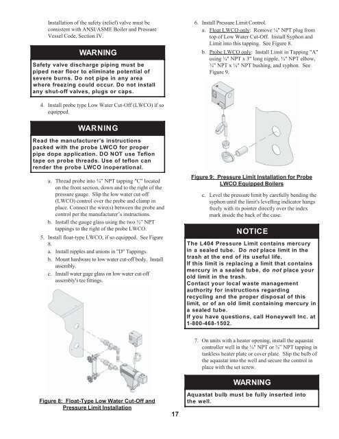
Installation of the safety (relief) valve must beconsistent with ANSI/ASME Boiler and PressureVessel Code, Section IV.WARNINGSafety valve discharge piping must bepiped near floor to eliminate potential ofsevere burns. Do not pipe in any areawhere freezing could occur. Do not installany shut-off valves, plugs or caps.6. Install Pressure Limit Control.a. Float LWCO only: Remove ¼" NPT plug fromtop of Low Water Cut-Off. Install Syphon andLimit into this tapping. See Figure 8.b. Probe LWCO only: Install Limit in Tapping "A"using ¾" NPT x 3" long nipple, ¾" NPT elbow,¾" NPT x ¼" NPT bushing, and syphon. SeeFigure 9.4. Install probe type Low Water Cut-Off (LWCO) if soequipped.WARNINGRead the manufacturer’s instructionspacked with the probe LWCO for properpipe dope application. DO NOT use Teflontape on probe threads. Use of teflon canrender the probe LWCO inoperational.a. Thread probe into ¾” NPT tapping "C" locatedon the front section, down and to the right of thepressure gauge. Slip the low water cut-off(LWCO) control over the probe and clamp inplace. Connect the wire(s) between the probe andcontrol per the manufacturer’s instructions.b. Install the gauge glass using the two ½” NPTtappings to the right of the probe LWCO.5. Install float-type LWCO, if so equipped. See Figure8.a. Install nipples and unions in "D" Tappings.b. Mount hardware to low water cut-off body. Installassembly.c. Install water gage glass on low water cut-offassembly's tee fittings.Figure 9: Pressure Limit Installation for ProbeLWCO Equipped Boilersc. Level the pressure limit by carefully bending thesyphon until the limit's levelling indicator hangsfreely with its pointer directly over the indexmark inside the back of the case.NOTICEThe L404 Pressure Limit contains mercuryina sealed tube. Do notplace limit in thetrash at the end of its useful life.If this limit is replacing a limit that containsmercuryin a sealed tube, do notplace yourold limit in the trash.Contact your local waste managementauthority for instructions regardingrecycling and the proper disposal of thislimit, or of an old limit containing mercury ina sealed tube.If you have questions, call Honeywell Inc. at1-800-468-1502.7. On units with a heater opening, install the aquastatcontroller well in the ½" NPT or ¾” NPT tapping intankless heater plate or cover plate. Slip the bulb ofthe aquastat into the well and secure the control inplace with the set screw.WARNINGFigure 8: Float-Type Low Water Cut-Off andPressure Limit Installation17Aquastatthe well.bulbmust befullyinsertedinto