Burnham V8 Series Instructions.pdf - Heating Help
Burnham V8 Series Instructions.pdf - Heating Help
Burnham V8 Series Instructions.pdf - Heating Help

Create successful ePaper yourself
Turn your PDF publications into a flip-book with our unique Google optimized e-Paper software.
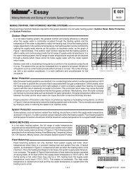
SECTION II: KNOCKDOWN BOILER ASSEMBLYA. REMOVAL OF BARE BOILER FROM SKID1. Boiler is secured to skid with 4 bolts, 2 in front and2 in rear of shipping skid, see Figure 3. Remove allbolts.G. INSTALL AND SECURE CANOPY with gasketand hardware provided to ensure gas tight seal — seeFigure 4.Figure 3: Knockdown Boiler Removal from Skid2. Tilt boiler to right and to rear. Using right rear leg aspivot, rotate boiler 90° in a clockwise direction, andlower left side of boiler to floor. Tilt boiler andremove skid.B. MOVE BOILER TO PERMANENT POSITIONby sliding or walking.C. TEST BOILER FOR LEAKS before installingcontrols, trim, and jacket, and before connecting toheating system.1. Loosen nuts on tie rods until only finger tight.2. Install pressure gauge (at least 50 PSI capacity), ahose to the city water and a valve in the supplytapping. Plug remainder of tappings.3. Fill boiler with water and apply a pressure of at least10 PSI but no more than 50 PSI gauge pressure.WARNINGAssure that there is no air left inside boilerwhen checking for leaks. Do not test forleaks with pressurized air.4. Examine boiler carefully inside and outside for leaksor damage due to shipment or handling.D. DRAIN WATER FROM BOILER. Remove gauge,valve and plugs from those tappings to be used. Leaveother tappings plugged or bushed according to Figure 5.E. INSPECT JOINTS BETWEEN SECTIONS. Alljoints are factory sealed. If there are any spaces due toshipment or handling, seal them with boiler putty.F. INSPECT FLUE COVER PLATES for tightness. Ifloose, retighten mounting hardware. If flue plate orsealing rope is damaged, repair or replace as needed.Figure 4: Boiler Canopy Installation1. Cut two (2) strips 13 ¾” long from the roll of gasketinsulation. Place one (1) strip across the top of thefront section and the other across the rear section asshown in Figure 4.2. Cut the remainder of the roll into two (2) equalpieces. Place each piece along the sides, allowingthe ends to overlap the front and rear pieces.CAUTIONDo not allow any flueway blockage bygasket.3. Position canopy body within the retaining bar whichborders the flueway openings on top of the bareboiler block assembly.NOTICEJacket support bracket must be facing leftside of boiler - see Figure 4. Jacket will notfit if bracket is not oriented correctly.4. Secure canopy to boiler with two (2) 1/4" - 20 x 3"long carriage bolts, 1/4" flat washers and 1/4" - 20wing nuts provided.12