Burnham V8 Series Instructions.pdf - Heating Help
Burnham V8 Series Instructions.pdf - Heating Help
Burnham V8 Series Instructions.pdf - Heating Help

You also want an ePaper? Increase the reach of your titles
YUMPU automatically turns print PDFs into web optimized ePapers that Google loves.
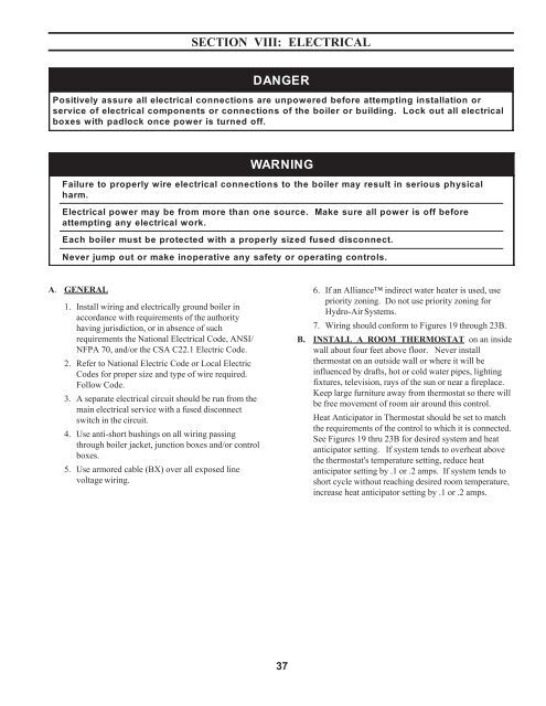
SECTION VIII: ELECTRICALDANGERPositively assure all electrical connections are unpowered before attempting installation orservice of electrical components or connections of the boiler or building. Lock out all electricalboxes with padlock once power is turned off.WARNINGFailureharm.toproperlywireelectrical connectionstotheboiler mayresult inseriousphysicalElectrical power may be from more than one source.attempting any electrical work.Make sure all power isEach boiler must be protected with a properly sized fused disconnect.off beforeNever jumpout or makeinoperativeanysafetyor operatingcontrols.A. GENERAL1. Install wiring and electrically ground boiler inaccordance with requirements of the authorityhaving jurisdiction, or in absence of suchrequirements the National Electrical Code, ANSI/NFPA 70, and/or the CSA C22.1 Electric Code.2. Refer to National Electric Code or Local ElectricCodes for proper size and type of wire required.Follow Code.3. A separate electrical circuit should be run from themain electrical service with a fused disconnectswitch in the circuit.4. Use anti-short bushings on all wiring passingthrough boiler jacket, junction boxes and/or controlboxes.5. Use armored cable (BX) over all exposed linevoltage wiring.6. If an Alliance indirect water heater is used, usepriority zoning. Do not use priority zoning forHydro-Air Systems.7. Wiring should conform to Figures 19 through 23B.B. INSTALL A ROOM THERMOSTAT on an insidewall about four feet above floor. Never installthermostat on an outside wall or where it will beinfluenced by drafts, hot or cold water pipes, lightingfixtures, television, rays of the sun or near a fireplace.Keep large furniture away from thermostat so there willbe free movement of room air around this control.Heat Anticipator in Thermostat should be set to matchthe requirements of the control to which it is connected.See Figures 19 thru 23B for desired system and heatanticipator setting. If system tends to overheat abovethe thermostat's temperature setting, reduce heatanticipator setting by .1 or .2 amps. If system tends toshort cycle without reaching desired room temperature,increase heat anticipator setting by .1 or .2 amps.37