Field Head mounted Temperature Transmitter TF02/TF02-Ex
Field Head mounted Temperature Transmitter TF02/TF02-Ex
Field Head mounted Temperature Transmitter TF02/TF02-Ex
You also want an ePaper? Increase the reach of your titles
YUMPU automatically turns print PDFs into web optimized ePapers that Google loves.
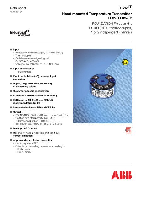
Data Sheet10/11-8.25 EN<strong>Field</strong>IT<strong>Head</strong> <strong>mounted</strong> <strong>Temperature</strong> <strong>Transmitter</strong><strong>TF02</strong>/<strong>TF02</strong>-<strong>Ex</strong>FOUNDATION <strong>Field</strong>bus H1,Pt 100 (RTD), thermocouples,1 or 2 independent channels■ Input– Resistance thermometer (2-, 3-, 4-wire circuit)– Thermocouples– Resistance remote signalling unit(0...500 Ω, 0...4000 Ω)– Voltages, mV calibrator (-125...+1200 mV)■ Input functionality– 1 or 2 channels■ Electrcal isolation (I/O) between inputand output■ Digital, long-term solid processingof measuring values■ Customer-specific linearization■ Continuous sensor and self-monitoring■ EMC acc. to EN 61326 and NAMURrecommendation NE 21■ Parameterization via DD and CFF file■ Output– FOUNDATION <strong>Field</strong>bus H1 acc. to specification 1.4– Certified with Interoperbility Test Kit 4.1– IT Campaign Number: IT 015000– Bus design acc. to IEC 61158-2, 31.25 kbit/s■ Backup LAS function■ Reserve voltage protection and solid buscurrent limitation■ Approvals for explosion protection– intrinsically safe ATEX– Suitable for connecting to systems according to:– Entity model– FISCO model
<strong>Head</strong> <strong>mounted</strong> <strong>Temperature</strong> <strong>Transmitter</strong> <strong>TF02</strong>/<strong>TF02</strong>-<strong>Ex</strong>FOUNDATION <strong>Field</strong>bus H1, Pt 100 (RTD), thermocouples, 1 or 2 independent channels10/11-8.25 ENTechnical dataDevice typeLink Master DeviceLink Active Scheduler (LAS) capability implementedPower supply (at transmitter terminals)Supply voltageU s = 9...32 V DCfor explosion protection applicationdependent on the <strong>Ex</strong> supply unitSupply voltage, poling protectedCurrent consumptionOperating (quiescent): 10.5 mAFault current limiting: 15 mAOutputInterface/ProtocolFOUNDATION <strong>Field</strong>bus H1 IEC 61158-2 / FF-H1Version 1.431.25 kbit/sFF Registration: IT015000 Interoperbility Test Kit 4.1Function blockstested function blocks 2 x AI (s)operating time: 25 msother function blocks 1 x RB (s)1 x TB (c)InputResistance (temperature linear)Resistance thermometern · Pt100 up to Pt1000 (IEC 751: n = 0.1; 0.5; 1; 2; 5; 10)(JIS 1604: n = 0.1; 0.5; 1; 2; 10) (SAMA: n = 0.1; 0.5; 1)Ni50, Ni100, Ni120, Ni1000, Cu10, Cu100Resistance Range Accuracy0...500 Ω 2 mΩ0...4000 Ω 20 mΩMax. line resistance (R W ) per core2-, 3-, 4-wire 5 Ω, 10 Ω, 50 ΩMeasuring current300 µASensor short-circuit< 5 ΩSensor break (temperature/resistance measurement, 2-, 3-, 4-wire)Measuring range 0... 500 Ω > 520 ΩMeasuring range 0...4000 Ω > 4200 ΩSensor wire break monitoring in accordance with NAMURSensor wire break detection3-wire resistance measurement > 35 Ω4-wire resistance measurement > 3.7 kΩInput filter50/60 HzThermocouplesTypesB, C, D, E, J, K, L, N, R, S, T, UVoltages Range Accuracy-100 mV...+1200 mV 10 µV- 75 mV...+ 75 mV 2 µVSensor monitoring current1 µA between the measuring cyclesSensor wire break monitoring in accordance with NAMURThermocouple measurement > 5 kΩVoltage measurement > 5 kΩInput filter50/60 HzInternal reference junctionPt100, via software switchable (no jumper necessary)Input elementMeasuring rangeStandardSensorIEC 584-1Thermocouple type B0...+1820 °C (+ 32...+3308 °F)Thermocouple type E-270...+1000 °C (-454...+1832 °F)Thermocouple type J-210...+1200 °C (-346...+2192 °F)Thermocouple type K-270...+1372 °C (-454...+2502 °F)Thermocouple type R- 50...+1768 °C (- 58...+3215 °F)Thermocouple type S- 50...+1768 °C (- 58...+3215 °F)Thermocouple type T-270...+ 400 °C (-454...+ 752 °F)Thermocouple type N-270...+1300 °C (-454...+2372 °F)W3,Thermocouple type C0...+2315 °C (+ 32...+4200 °F)ASTME 998Thermocouple type D0...+2315 °C (+ 32...+4200 °F)DIN 43710Thermocouple type L-200...+ 900 °C (-328...+1652 °F)Thermocouple type U-200...+ 600 °C (-328...+1112 °F)IEC 751; JIS; SAMA 1)Resistance thermometer Pt100-200...+ 850 °C (-328...+1562 °F)2-, 3- and 4-wireResistance thermometer Pt1000-200...+ 850 °C (-328...+1562 °F)DIN 43760 2)Resistance thermometer Ni100- 60...+ 250 °C (- 76...+ 482 °F)2-, 3- and 4-wire (a = 0.00618) Resistance thermometer Ni1000- 60...+ 250 °C (- 76...+ 482 °F)Resistance, 2-, 3- and 4-wire Ω 0...500 Ω / 0...4000 ΩVoltage mV -100 mV...+1200 mV- 75 mV...+ 75 mV1) IEC 751 a = 0.00385; JIS a = 0.003916; SAMA a = 0.0039022) Edison Curve No.7 for Ni1202
<strong>Head</strong> <strong>mounted</strong> <strong>Temperature</strong> <strong>Transmitter</strong> <strong>TF02</strong>/<strong>TF02</strong>-<strong>Ex</strong>FOUNDATION <strong>Field</strong>bus H1, Pt 100 (RTD), thermocouples, 1 or 2 independent channels10/11-8.25 ENGeneral characteristicsResponse time< 0.5 sVibration resistanceVibration in operationResistance to shockElectrical isolation (I/O)1.5 kV ACLong-term stability≤ 0.1 % p. a. or 0.2 K p. a.Environment conditions2 g acc. to DIN IEC 68T.2-62 g acc. to DIN IEC 68T.2-27Ambient temperature range-40...+85 °CTransport and storage temperature-40...+100 °CRelative humidity< 100 % (100 % humidity with isolated terminals only)CondensationpermittedMechanical constructionDimensionscf. dimensional drawingWeight61 gHousing materialPolycarbonatColor (Epoxy)black (Non-<strong>Ex</strong> type), blue (<strong>Ex</strong>-type)Terminals, pluggable2.5 mm 2 , screw terminals (stainless steel screws)InfluencesInfluence of ambient temperaturePt 100± 0.025 K/10 Kresistance measurement 0...500 W ± 10 mΩ/10 K0...4000 Ω ± 100 mΩ/10 KThermocouple e. g. type K± 0.025 K/10 Kvoltage measurement -100 mV...+1200 mV ± 150 µV/10 K- 75 mV...+ 75 mV ± 10 µV/10 KCharacteristics at rated conditionsacc. to IEC 770 (related to 25 °C)Measuring error incl. characteristic deviationPt 100± 0.1 Kresistance measurement 0...500 Ω± 40 mΩ0...4000 Ω ± 320 mΩThermocouple e. g. type K± 0.25 Kvoltage measurement -100 mV...+1200 mV ± 50 µV- 75 mV...+ 75 mV ± 10 µVAdditional influence ofthe internal ref. junctionPt100 DIN IEC 751 Cl. BParameterization / structureType of input (2 independent channels), measuring range,input filter, damping, alarm function, limit values, safing alldata proof against mains failureStandard parameter (factory settings)Channel 1Pt100, 4-wire circuit, 0…+100 °Cdamping 0 s, unit °CChannel 2disabledElectromagnetic compatibility (EMC)According to NAMUR NE 21 recommendationWith Pt100 sensor and thermocoupleType of test Degree StandardBurst to signal/data lines1 kV EN 61000-4-4EN 61326Static disgargeEN 61000-4-2contact discharge to:contact plateterminals8 kV6 kVradiated fieldEN 61000-4-380 MHz...2 GHz 10 V/mcoupling150 kHz - 80 MHz 10 VEN 61000-4-63
<strong>Head</strong> <strong>mounted</strong> <strong>Temperature</strong> <strong>Transmitter</strong> <strong>TF02</strong>/<strong>TF02</strong>-<strong>Ex</strong>FOUNDATION <strong>Field</strong>bus H1, Pt 100 (RTD), thermocouples, 1 or 2 independent channels10/11-8.25 EN<strong>Ex</strong>plosion protectionIntrinsically safeEC Certificate DMT 02 ATEX E 068 X(Intrinsically safe Zone 0/1 and Mine)Zone 0/1II 1 G E<strong>Ex</strong> ia IIC T6Zone 0 T1…T5 Ambient temperature: -20…+60 °CT6 Ambient temperature: -20…+50 °CZone 1 T1…T4 Ambient temperature: -40…+85 °CT5 Ambient temperature: -40…+65 °CT6 Ambient temperature: -40…+50 °CMineSupply circuitSupply andcommunicationcircuitia/ib IICI M 1 E<strong>Ex</strong> ia IAmbient temperature: -20…+60 °CSupply andcommunicationcircuitia/ib IIBMeasuringcircuit ia/ibMax. voltage U i ≤ 24 V U i ≤ 24 V U o = 5.5 VShort-circuit current I i = 360 mA I i = 380 mA I o < 25 mAMax. power P i = 2.52 W P i = 5.32 W P o < 35 mWInternal inductance L i ≤ 10 µH L i ≤ 10 µH neglectableInternal capacitance C i = 5 nF C i = 5 nF C i = 60 nFNon sparking “nA“ ATEXEC Certificate BVS 03 E 171 XZone 2 (<strong>TF02</strong>-<strong>Ex</strong> N)II 3 G E<strong>Ex</strong> nA [nL] IIC T6T1…T4 Ambient temperature: -40…+85 °CT1...T5 Ambient temperature: -40…+65 °CT1...T6 Ambient temperature: -40…+50 °CCanadian Standards Association and Factory MutualIntrinsically SafeFM Class I Div. 1/Div. 2, Groups A, B, C, D T6Class I Zone 0, A<strong>Ex</strong> iaor Zone 0, A<strong>Ex</strong> ib IICCSA Class I Div. 1/Div. 2, Groups A, B, C, D T6NonincendiveFM Class I Div. 2, Groups A, B, C, D T6CSA Class I Div. 2, Groups A, B, C, D T6Suitable for connceting to systems according to– Entity model and– FISCO modelBlock diagramSensor 1; (T1)Value_1 (T1)AI Block 1AI 1out value sensor 1+ StatusTransducer BlockTBValue_2 (T2)AI Block 2AI 2out value sensor 2+ StatusSensor 2; (T2)Resource BlockReference junctionPt100by requestonly readby requestread/write4
<strong>Head</strong> <strong>mounted</strong> <strong>Temperature</strong> <strong>Transmitter</strong> <strong>TF02</strong>/<strong>TF02</strong>-<strong>Ex</strong>FOUNDATION <strong>Field</strong>bus H1, Pt 100 (RTD), thermocouples, 1 or 2 independent channels10/11-8.25 ENConnection diagram+OutputMicroprocessorInput131313131Ch13ϑ13131Ch131Ch13131Ch13-Foundation<strong>Field</strong>bus (H1)Referencejunction4242ϑ ϑ ϑ4 4 4Ch22 2 2ϑ424Ch224Ch22ϑ4Ch22a) b) c) d) e) f) g) h) i) j)a) Resistance thermometer, 2-wire circuitb) Resistance thermometer, 3-wire circuitc) Resistance thermometer, 4-wire circuitd) Double resistance thermometer, 2-wire circuit(average value or differential temperature measurement)e) Potentiometer input (4-wire circuit)– Resistance measurement analogous to resistance thermometercircuits a) to d)f) Thermocoupleg) Double thermocouple (average value or differentialtemperature measurement)h) Combination thermocouple resistance thermometeri) Voltage measurementj) Double voltage measurement (average value or differentialtemperature measurement)– Voltage measurement and resistance measurementanalogous to circuit h) also possibleDimensional drawing (dimensions in mm)2431∅ 44,4Automation - ProductsTF 02Messumformer/<strong>Transmitter</strong>/Transducteur23,8Snap-on fixing for DIN rail mounting(35mm)(optionally)5,55
<strong>Head</strong> <strong>mounted</strong> <strong>Temperature</strong> <strong>Transmitter</strong> <strong>TF02</strong>/<strong>TF02</strong>-<strong>Ex</strong>FOUNDATION <strong>Field</strong>bus H1, Pt 100 (RTD), thermocouples, 1 or 2 independent channels10/11-8.25 ENOrdering informationCatalog No. EUR Deliv. time<strong>TF02</strong>/<strong>TF02</strong>-<strong>Ex</strong> V11527- - 3 wks.Bus systemFOUNDATION <strong>Field</strong>bus (H1) acc. to <strong>Field</strong>bus standard IEC-61158-2; 31.25 kbit/sLAS functionality standard FR -LAS functionality among using in combination with FIO100 or LD 800HSE from ABB FA -<strong>Ex</strong>plosion protection<strong>TF02</strong> (without explosion protection) 1 424,00 *Type of protection: Non Sparking "nA" ATEX<strong>TF02</strong>-<strong>Ex</strong> N DMT/ATEX Zone 2: II 3 G E<strong>Ex</strong> nA [nL] IIC T6 N 455,00 *Type of protection: intrinsically safe ATEX<strong>TF02</strong>-<strong>Ex</strong> DMT/ATEX Zone 0: II 1 G E<strong>Ex</strong> ia IIC T6 (+ Mine: I M 1 E<strong>Ex</strong> ia I) 5 455,00 *Type of protection: intrinsically safe FM and CSA<strong>TF02</strong>-<strong>Ex</strong> FM IS Class I, Div. 1/Div. 2, Groups A, B, C, D T6 7 455,00 *IS Class I, Zone 0, A<strong>Ex</strong> ia oder A<strong>Ex</strong> ib IIC(Class II Groups E ,F, G; Class III if built in BUZH head or AGLH head)nonincendive, Class I, Div. 2, Groups A, B, C, D T6(Class II Groups F, G; Class III if built in BUZH head or AGLH head)<strong>TF02</strong>-<strong>Ex</strong> CSA IS Class I, Div. 1 and Div. 2, Groups A, B, C, D T6 9 455,00 *(Class II Groups E, F, G; Class III if built in BUZH head or AGLH head)nonincendive, Class I, Div. 2, Groups A,B,C,D T6(Class II Groups F, G; Class III if built in BUZH head or AGLH head)ConstructionModule 3 -Module with sensor connecting line 1 7,62 *Module with snap-on fixing 4 10,00 *Module built into connection head with sensor connecting lineBUZH head R 41,30 *BUSH head P 41,80 *BUKH-<strong>Ex</strong> head N 33,60 *AUZH head V 55,20 *AUSH head U 56,40 *AGLH-head without display 1) X 63,60 *Attention: The sensor connecting lines correspond to the order for the type of sensoror its type of circuitryConnectionsno head selected 0 -with cable screw connections M20 x 1,5 cable screw connection 2) M 19,40 *ProgrammingFactory standard parameter Pt 100, 4-wire circuit, 1 channel, 0…100°C, Damping off 0 -Customer-specified parameter definition (all parameter without user curve) 1 35,90 *AccessoriesCatalog No. EUR Deliv. timeSimulation plug for <strong>TF02</strong>/TF202 with bus system FOUNDATION <strong>Field</strong>bus 7957851 12,20 *1) protective pipe connection M24 x 1.5 (optional M20 x 1.5; 1/2" NPT; 3/4" NPT)2) Standard: Aluminum, metal-cable-screw-connection M20 x 1.5 E<strong>Ex</strong> e (cable diameter 3.5…8.7 mm);(do not use for E<strong>Ex</strong> d applications, see data sheet 10/10-3.28 EN for E<strong>Ex</strong> d details)6
The Industrial IT wordmark and all mentionedproduct names in the form XXXXXX IT are registeredor pending trademarks of ABB.The Company’s policy is one of continuous productimprovement and the right is reserved to modify theinformation contained herein without notice.ABB has Sales & Customer Supportexpertise in over 100 countries worldwide.www.abb.comPrinted in the Fed. Rep. of Germany (05.04)© ABB 200410/11-8.25 EN Rev. AABB Ltd.Salterbeck Trading EstateWorkington, Cumbria, CA14 5DSUKTel: +44(0)1946-830-611Fax: +44(0)1946-832-661ABB Inc.125 E. County Line RoadWarminster, PA 18974USATel: +1 215-674-6000Fax: +1 215-674-7183ABB Automation Products GmbHBorsigstr. 263755 AlzenauGermanyTel: +49 551 905-534Fax: +49 551 905-555CCC-support.deapr@de.abb.com


![[MI 019-120] I/A Series Mass Flowtubes Models CFS20 ... - Invensys](https://img.yumpu.com/48832334/1/190x245/mi-019-120-i-a-series-mass-flowtubes-models-cfs20-invensys.jpg?quality=85)
