Temperature Transmitters TF02/TF02-Ex (head mounted) and ...
Temperature Transmitters TF02/TF02-Ex (head mounted) and ...
Temperature Transmitters TF02/TF02-Ex (head mounted) and ...

Create successful ePaper yourself
Turn your PDF publications into a flip-book with our unique Google optimized e-Paper software.
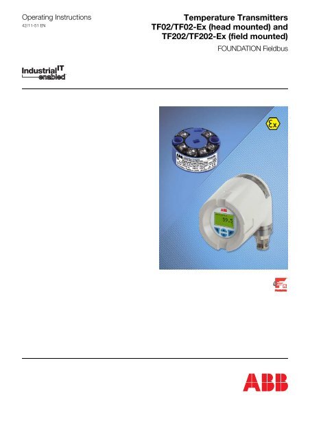
Operating Instructions42/11-51 EN<strong>Temperature</strong> <strong>Transmitters</strong><strong>TF02</strong>/<strong>TF02</strong>-<strong>Ex</strong> (<strong>head</strong> <strong>mounted</strong>) <strong>and</strong>TF202/TF202-<strong>Ex</strong> (field <strong>mounted</strong>)FOUNDATION Fieldbus
<strong>Temperature</strong> <strong>Transmitters</strong><strong>TF02</strong>/<strong>TF02</strong>-<strong>Ex</strong> (<strong>head</strong> <strong>mounted</strong>) <strong>and</strong>TF202/TF202-<strong>Ex</strong> (field <strong>mounted</strong>)FOUNDATION FieldbusOperating InstructionsDocument No.:42/11-51 ENDate of issue: 09.2008Revision: 02ManufacturerABB Automation Products GmbHBorsigstr. 263755 AlzenauGermanyTel: +49 551 905-534Fax: +49 551 905-555CCC-Support.deapr@de.abb.com© Copyright 2008 by ABB Automation Products GmbHWe reserve the right to technical amendments.This document is protected by copyright. Information in this document is intended only to assist the user in thesafe <strong>and</strong> efficient operation of the equipment. Its contents are not to be reproduced in full or part without priorapproval of the legal owner.2 <strong>Temperature</strong> <strong>Transmitters</strong> <strong>TF02</strong>/<strong>TF02</strong>-<strong>Ex</strong> (<strong>head</strong> <strong>mounted</strong>) <strong>and</strong> TF202/TF202-<strong>Ex</strong> (field <strong>mounted</strong>) 42/11-51 EN
Contents . . . . . . . . . . . . . . . . . . . . . . . . . . . . . . . . . . . . . . . . . . . . . . . . . . . . . . . . . . . . . . . . . . . . . . . . . . PageImportant information . . . . . . . . . . . . . . . . . . . . . . . . . . . . . . . . . . . . . . . . . . . . . . . . . . . . . . . . . . . . . . . . . 41 Introduction . . . . . . . . . . . . . . . . . . . . . . . . . . . . . . . . . . . . . . . . . . . . . . . . . . . . . . . . . . . . . . . . . . . . 51.1 Device features . . . . . . . . . . . . . . . . . . . . . . . . . . . . . . . . . . . . . . . . . . . . . . . . . . . . . . . . . . . . . 51.2 Using this manual . . . . . . . . . . . . . . . . . . . . . . . . . . . . . . . . . . . . . . . . . . . . . . . . . . . . . . . . . . . 51.3 General Safety Instructions! . . . . . . . . . . . . . . . . . . . . . . . . . . . . . . . . . . . . . . . . . . . . . . . . . . . 51.4 Additional safety instructions for <strong>TF02</strong>-<strong>Ex</strong> <strong>and</strong> TF202-<strong>Ex</strong>! . . . . . . . . . . . . . . . . . . . . . . . . . . . . 61.5 Supplementary documentation! . . . . . . . . . . . . . . . . . . . . . . . . . . . . . . . . . . . . . . . . . . . . . . . . 61.6 Declaration of Conformity . . . . . . . . . . . . . . . . . . . . . . . . . . . . . . . . . . . . . . . . . . . . . . . . . . . . . 61.7 Maintenance . . . . . . . . . . . . . . . . . . . . . . . . . . . . . . . . . . . . . . . . . . . . . . . . . . . . . . . . . . . . . . . 71.8 Repair of explosion-proof devices. . . . . . . . . . . . . . . . . . . . . . . . . . . . . . . . . . . . . . . . . . . . . . . 72 Device Specification . . . . . . . . . . . . . . . . . . . . . . . . . . . . . . . . . . . . . . . . . . . . . . . . . . . . . . . . . . . . 72.1 Communication Interface . . . . . . . . . . . . . . . . . . . . . . . . . . . . . . . . . . . . . . . . . . . . . . . . . . . . . 72.1.1 Physical layer . . . . . . . . . . . . . . . . . . . . . . . . . . . . . . . . . . . . . . . . . . . . . . . . . . . . . . . . . . . . . . 72.1.2 Protocol . . . . . . . . . . . . . . . . . . . . . . . . . . . . . . . . . . . . . . . . . . . . . . . . . . . . . . . . . . . . . . . . . . 73 Mounting . . . . . . . . . . . . . . . . . . . . . . . . . . . . . . . . . . . . . . . . . . . . . . . . . . . . . . . . . . . . . . . . . . . . . . . 83.1 <strong>TF02</strong> / TF202 installation sites . . . . . . . . . . . . . . . . . . . . . . . . . . . . . . . . . . . . . . . . . . . . . . . . . 83.1.1 Mounting <strong>TF02</strong> / <strong>TF02</strong>-<strong>Ex</strong> . . . . . . . . . . . . . . . . . . . . . . . . . . . . . . . . . . . . . . . . . . . . . . . . . . . . 83.1.2 Mounting TF202 / TF202-<strong>Ex</strong> . . . . . . . . . . . . . . . . . . . . . . . . . . . . . . . . . . . . . . . . . . . . . . . . . . 93.1.3 Applications with hazardous areas . . . . . . . . . . . . . . . . . . . . . . . . . . . . . . . . . . . . . . . . . . . . . 113.1.4 Applications in safe areas . . . . . . . . . . . . . . . . . . . . . . . . . . . . . . . . . . . . . . . . . . . . . . . . . . . 113.1.5 Environment conditons . . . . . . . . . . . . . . . . . . . . . . . . . . . . . . . . . . . . . . . . . . . . . . . . . . . . . . 123.2 Cabling / connecting the device . . . . . . . . . . . . . . . . . . . . . . . . . . . . . . . . . . . . . . . . . . . . . . . 123.2.1 Fieldbus interface . . . . . . . . . . . . . . . . . . . . . . . . . . . . . . . . . . . . . . . . . . . . . . . . . . . . . . . . . . 123.2.2 Sensor interface . . . . . . . . . . . . . . . . . . . . . . . . . . . . . . . . . . . . . . . . . . . . . . . . . . . . . . . . . . . 133.3 Shielding, grounding, EMC . . . . . . . . . . . . . . . . . . . . . . . . . . . . . . . . . . . . . . . . . . . . . . . . . . . 133.4 Maintenance, repair, trouble-shooting. . . . . . . . . . . . . . . . . . . . . . . . . . . . . . . . . . . . . . . . . . . 144 Fieldbus Communication . . . . . . . . . . . . . . . . . . . . . . . . . . . . . . . . . . . . . . . . . . . . . . . . . . . . . . . 154.1 Block structure . . . . . . . . . . . . . . . . . . . . . . . . . . . . . . . . . . . . . . . . . . . . . . . . . . . . . . . . . . . . 154.2 Resource Block. . . . . . . . . . . . . . . . . . . . . . . . . . . . . . . . . . . . . . . . . . . . . . . . . . . . . . . . . . . . 154.2.1 Overview . . . . . . . . . . . . . . . . . . . . . . . . . . . . . . . . . . . . . . . . . . . . . . . . . . . . . . . . . . . . . . . . 154.2.2 Description . . . . . . . . . . . . . . . . . . . . . . . . . . . . . . . . . . . . . . . . . . . . . . . . . . . . . . . . . . . . . . . 154.3 Transducer Block . . . . . . . . . . . . . . . . . . . . . . . . . . . . . . . . . . . . . . . . . . . . . . . . . . . . . . . . . . 184.3.1 Overview . . . . . . . . . . . . . . . . . . . . . . . . . . . . . . . . . . . . . . . . . . . . . . . . . . . . . . . . . . . . . . . . 184.3.2 Description . . . . . . . . . . . . . . . . . . . . . . . . . . . . . . . . . . . . . . . . . . . . . . . . . . . . . . . . . . . . . . . 194.3.3 Objects / Parameters of the Transducer Block . . . . . . . . . . . . . . . . . . . . . . . . . . . . . . . . . . . 214.4 AI Block. . . . . . . . . . . . . . . . . . . . . . . . . . . . . . . . . . . . . . . . . . . . . . . . . . . . . . . . . . . . . . . . . . 244.4.1 Overview . . . . . . . . . . . . . . . . . . . . . . . . . . . . . . . . . . . . . . . . . . . . . . . . . . . . . . . . . . . . . . . . 244.4.2 Description . . . . . . . . . . . . . . . . . . . . . . . . . . . . . . . . . . . . . . . . . . . . . . . . . . . . . . . . . . . . . . . 254.4.3 Scaling of the analog input value . . . . . . . . . . . . . . . . . . . . . . . . . . . . . . . . . . . . . . . . . . . . . . 254.4.4 Alarms of the AI Block . . . . . . . . . . . . . . . . . . . . . . . . . . . . . . . . . . . . . . . . . . . . . . . . . . . . . . 264.4.5 Simulation of the input value . . . . . . . . . . . . . . . . . . . . . . . . . . . . . . . . . . . . . . . . . . . . . . . . . 274.4.6 Objects / Parameters of the AI Block . . . . . . . . . . . . . . . . . . . . . . . . . . . . . . . . . . . . . . . . . . . 27Value & Status Byte . . . . . . . . . . . . . . . . . . . . . . . . . . . . . . . . . . . . . . . . . . . . . . . . . . . . . . . . 305 Commissioning . . . . . . . . . . . . . . . . . . . . . . . . . . . . . . . . . . . . . . . . . . . . . . . . . . . . . . . . . . . . . . . . 325.1 Device Description (DD) . . . . . . . . . . . . . . . . . . . . . . . . . . . . . . . . . . . . . . . . . . . . . . . . . . . . . 325.2 Capabilities File Format (CFF) . . . . . . . . . . . . . . . . . . . . . . . . . . . . . . . . . . . . . . . . . . . . . . . . 325.3 Commissioning with ABB Control Builder F <strong>and</strong> FIO-100. . . . . . . . . . . . . . . . . . . . . . . . . . . . 326 Technical Data . . . . . . . . . . . . . . . . . . . . . . . . . . . . . . . . . . . . . . . . . . . . . . . . . . . . . . . . . . . . . . . . 336.1 Technical data <strong>TF02</strong>/<strong>TF02</strong>-<strong>Ex</strong>/TF202/TF202-<strong>Ex</strong> . . . . . . . . . . . . . . . . . . . . . . . . . . . . . . . . . . 336.2 Mecanical construction <strong>TF02</strong>/<strong>TF02</strong>-<strong>Ex</strong> . . . . . . . . . . . . . . . . . . . . . . . . . . . . . . . . . . . . . . . . . . 346.3 Mechanical construction TF202/TF202-<strong>Ex</strong> . . . . . . . . . . . . . . . . . . . . . . . . . . . . . . . . . . . . . . . 346.4 <strong>Ex</strong>plosion protection <strong>TF02</strong>-<strong>Ex</strong> . . . . . . . . . . . . . . . . . . . . . . . . . . . . . . . . . . . . . . . . . . . . . . . . . 356.5 <strong>Ex</strong>plosion protection TF202-<strong>Ex</strong> . . . . . . . . . . . . . . . . . . . . . . . . . . . . . . . . . . . . . . . . . . . . . . . . 357 EEC Certificate of Conformity . . . . . . . . . . . . . . . . . . . . . . . . . . . . . . . . . . . . . . . . . . . . . . . . . . 3642/11-51 EN <strong>Temperature</strong> <strong>Transmitters</strong> <strong>TF02</strong>/<strong>TF02</strong>-<strong>Ex</strong> (<strong>head</strong> <strong>mounted</strong>) <strong>and</strong> TF202/TF202-<strong>Ex</strong> (field <strong>mounted</strong>) 3
Important informationSymbolsIn order that you can make the best use of this document <strong>and</strong> to ensure safety during commissioning, operation<strong>and</strong> maintenance of the equipment, please note the following explanation of the symbols used.<strong>Ex</strong>planation of the symbols used.Symbol Signal Word DefinitionsDANGER DANGER indicates an imminently hazardous situation which, if not avoided,will result in death or serious injury.(High level of risk.)WARNINGCAUTIONNOTICEWARNING indicates a potentially hazardous situation which, if not avoided,could result in death or serious injury.(Medium level of risk.)CAUTION indicates a potentially hazardous situation which, if not avoided,could result in minor or moderate injury.(Low level of risk.)NOTICE indicates a potentially harmful situation which, if not avoided,may result in damage of the product itself or of adjacent objects.(Damage to property)IMPORTANT IMPORTANT indicates useful hints or other special information which, if notobserved, could lead to a decline in operating convenience or affect thefunctionality.(Does not indicate a dangerous or harmful situation.)As well as the instructions in this document, you must also follow the generally applicable accident prevention<strong>and</strong> safety regulations.If the information in this document is insufficient in any situation, please contact our service department, who willbe happy to help you.Please read this document carefully before installation <strong>and</strong> commissioning.CE MARKINGThis product meets the requirements specified in EMC Directive 89/336/EEC <strong>and</strong> in Low Voltage Directive 73/23/EEC. Additional for the explosion proof versions <strong>TF02</strong>-<strong>Ex</strong>/TF202-<strong>Ex</strong> the protection regulations of the EuropeanGuidelines 94/9 EEC are fulfilled.4 <strong>Temperature</strong> <strong>Transmitters</strong> <strong>TF02</strong>/<strong>TF02</strong>-<strong>Ex</strong> (<strong>head</strong> <strong>mounted</strong>) <strong>and</strong> TF202/TF202-<strong>Ex</strong> (field <strong>mounted</strong>) 42/11-51 EN
Introduction1 Introduction1.1 Device featuresThe transmitter <strong>TF02</strong> / <strong>TF02</strong>-<strong>Ex</strong> / TF202 / TF202-<strong>Ex</strong> is used to measure temperature <strong>and</strong> other process variables.It converts the input variable into digital values. These values are transmitting with field bus technology.The <strong>TF02</strong> / TF202 are for connecting to field bus with design according to IEC 1158-2, 31,25 kbits/s. The supportedfield bus protocol is FOUNDATIONTM Fieldbus.The <strong>TF02</strong> / TF202 is available in Non <strong>Ex</strong> version (<strong>TF02</strong> / TF202) <strong>and</strong> in <strong>Ex</strong> version (<strong>TF02</strong>-<strong>Ex</strong> / TF202-<strong>Ex</strong>).The difference between <strong>TF02</strong> <strong>and</strong> TF202 (including <strong>Ex</strong> versions) is only the housing.<strong>TF02</strong> / <strong>TF02</strong>-<strong>Ex</strong>: <strong>head</strong> <strong>mounted</strong> temperature transmitterTF202 / TF202-<strong>Ex</strong>: field <strong>mounted</strong> temperature transmitter(<strong>TF02</strong> built in field <strong>mounted</strong> housing)1.2 Using this manualThe four variants <strong>TF02</strong> / <strong>TF02</strong>-<strong>Ex</strong> / TF202 / TF202-<strong>Ex</strong> are referred as <strong>TF02</strong> in this manual.1.3 General Safety Instructions!Proper <strong>and</strong> safe operation of the <strong>TF02</strong> / <strong>TF02</strong>-<strong>Ex</strong> / TF202 / TF202-<strong>Ex</strong> temperature transmitter requires propertransportation <strong>and</strong> storage, installation <strong>and</strong> commissioning by qualified personnel, correct operation accordingto the instructions, proper use <strong>and</strong> careful maintenance.Only qualified personnel who are familiar with the installation, commissioning, operation <strong>and</strong> maintenance of thisor similar devices are allowed to work on the device.The unit <strong>TF02</strong> / <strong>TF02</strong>-<strong>Ex</strong> / TF202 / TF202-<strong>Ex</strong> has been constructed <strong>and</strong> tested in accordance with IEC 1010-1(corresponds to EN 61 010-1 corresponds to DIN VDE 0411 Part 1 "Safety requirements for electrical process,instrumentation <strong>and</strong> laboratory units"),– possesses CE certification <strong>and</strong>– has left the factory in a perfect technical <strong>and</strong> safe condition.In order to retain this condition when dealing with the unit (transportation, storage, maintenance, commissioning,operation, servicing, switch off)– contents of the Operation Manual <strong>and</strong>– the ratings plates attached to the unit, inscriptions <strong>and</strong> safety instructionsmust be observed.Otherwise– persons could be endangered <strong>and</strong>– the unit itself, as well as other equipment could be damaged.The safe separation of live currents can only be assured, if the connected apparatus meets the requirements ofVDE 0106 T.101 (basic st<strong>and</strong>ards for electrical safety).Before switching on the apparatus make sure that the ambient conditions stated in the Data Sheet <strong>and</strong> the OperationInstructions are met <strong>and</strong> also that the voltage of the power supply units is identical with the voltage of theunit <strong>TF02</strong> / <strong>TF02</strong>-<strong>Ex</strong> / TF202 / TF202-<strong>Ex</strong>.Whenever it can be assumed that harmless operation is no longer possible, the apparatus should be inoperative<strong>and</strong> secured against any unintended operation.The directives, norms <strong>and</strong> guidelines mentioned in the Operation Manual are applicable in the Federal Republicof Germany. When using the unit in other countries, please observe the national regulations prevailing in therespective country.Should the information provided in the Operation Manual prove to be insufficient, please do not hesitate to usethe address list provided on the back of this manual to contact the manufacture.42/11-51 EN <strong>Temperature</strong> <strong>Transmitters</strong> <strong>TF02</strong>/<strong>TF02</strong>-<strong>Ex</strong> (<strong>head</strong> <strong>mounted</strong>) <strong>and</strong> TF202/TF202-<strong>Ex</strong> (field <strong>mounted</strong>) 5
1.4 Additional safety instructions for <strong>TF02</strong>-<strong>Ex</strong> <strong>and</strong> TF202-<strong>Ex</strong>!IntroductionDuring all work on <strong>TF02</strong>-<strong>Ex</strong> or TF202-<strong>Ex</strong> the EEC Certificate of Conformity DMT 02 ATEX E068 X must be observed.<strong>TF02</strong>-<strong>Ex</strong> <strong>and</strong> TF202-<strong>Ex</strong> are certified for installation in Zone 0 <strong>and</strong> Zone 1 (according to ATEX) of hazardous locations.The measuring circuits as well as the fieldbus connection are in accordance to E<strong>Ex</strong> ia. The required fieldbuspower supply connection or conditioner for the supply of the transmitter (IEC 61158-2) must be selectedaccording to the <strong>Ex</strong> classification.The <strong>TF02</strong>-<strong>Ex</strong> shall be <strong>mounted</strong> in an enclosure, ensuring housing protection of IP20 according to EN 60529.For grounding measures on the bus cable (e.g. shield) the guidelines given in IEC 60 079-14 or EN 60 079-14must be followed.If an apparatus with an intrinsically safe circuit is connected to the transmitter, proof of the intrinsic safety of theconnection must be provided in accordance with DIN VDE 0165 / 08.98 (= EN 60 079-14 <strong>and</strong> IEC 60 079-14)respectively.When working on an explosion-proof device, the st<strong>and</strong>ard EN 60 079-17 must be followed. Before commencingwork, please ensure that safety measures regarding explosion protection have been taken!DANGEROnly qualified personnel who are familiar with this product <strong>and</strong> its mounting, commissioning <strong>and</strong> operatingprocedures are allowed to mount, install, commission <strong>and</strong> operate the device. Qualified personnel,according to the underst<strong>and</strong>ing of this manual, are those people who were trained adequately, have therequired experience, <strong>and</strong> know the relevant safety st<strong>and</strong>ards to be able to assess the tasks assigned tothem <strong>and</strong> to recognize possible safety hazard. People working on explosion-proof devices for use in hazardousareas must prove that they have been trained adequately <strong>and</strong> are allowed to perform suchwork.The device must be transported <strong>and</strong> stored properly.Each mine application (category IM 1) involving the temperature transmitter <strong>TF02</strong>-<strong>Ex</strong> <strong>and</strong> TF202-<strong>Ex</strong> must be verifiedby the local certifying body in regards to the interconnection of the devices within hazardous areas.For mine applications the <strong>head</strong> <strong>mounted</strong> temperature transmitter <strong>TF02</strong>-<strong>Ex</strong> must be <strong>mounted</strong> in a housing certifiedfor mine application category IM1.Available ABB types are the stainless steel connection <strong>head</strong> types AGS, AGSH, AGSDThe TF202-<strong>Ex</strong> version certified for Mine applications (category IM 1) is only available in conjunction with the fieldhousing ABB Types AGSF, AGSFH, AGSFD1.5 Supplementary documentation!For <strong>Ex</strong>-certified devices, the Certificate of Conformity must be read prior to the installation. In case you needsupplement information, please feel free to contact us (see address on last page of this documentation) or downloadthe information from our web page (ww.abb.com). A list of supplementary information is given below:<strong>TF02</strong> / <strong>TF02</strong>-<strong>Ex</strong> Data Sheet 11/10-8.25EC Type <strong>Ex</strong>amination Certificate DMT 02 ATEX E068 XTF202 / TF202-<strong>Ex</strong> Data Sheet 11/10-8.69EC Type <strong>Ex</strong>amination Certificate DMT 02 ATEX E068 X1.6 Declaration of ConformityThe protective regulations of the European guidelines 94/9/EG as well as the EN 50 014 <strong>and</strong> the EN 50 020 arefulfilled.6 <strong>Temperature</strong> <strong>Transmitters</strong> <strong>TF02</strong>/<strong>TF02</strong>-<strong>Ex</strong> (<strong>head</strong> <strong>mounted</strong>) <strong>and</strong> TF202/TF202-<strong>Ex</strong> (field <strong>mounted</strong>) 42/11-51 EN
1.7 MaintenanceDevice SpecificationThe device is maintenance-free.Devices or components that are damaged or suspect to be damaged must not be used any longer.1.8 Repair of explosion-proof devicesAfter repair, an expert in accordance with the explosion protection regulations must test the device before theycan be used again. Successful passing of the test must be confirmed in writing or through a test mark. This testis not required, if the part is submitted to a routine check test by the manufacturer <strong>and</strong> successful passing of thetest is indicated through a conformity mark attached to the device.2 Device Specification2.1 Communication Interface2.1.1 Physical layerThe communication interface meets the rules for Foundation Fieldbus <strong>and</strong> PROFIBUS PA devices. The devicefulfills both Intrinsically Safe (I.S.) <strong>and</strong> normal requirements on the physical layer. The specification FF-816 describesthe Physical Layer. The baudrate of the fieldbus transmission is fixed to 31.25 kBit/s.2.1.2 Protocol– Foundation Fieldbus Specification 1.4– Certified with Interoperability Test Kit 4– IT Campain Number: IT015000The <strong>TF02</strong> fulfills all requirement regarding the FF-940 specification of a Group 3 / Class 31 compatible device.42/11-51 EN <strong>Temperature</strong> <strong>Transmitters</strong> <strong>TF02</strong>/<strong>TF02</strong>-<strong>Ex</strong> (<strong>head</strong> <strong>mounted</strong>) <strong>and</strong> TF202/TF202-<strong>Ex</strong> (field <strong>mounted</strong>) 7
Mounting3 Mounting3.1 <strong>TF02</strong> / TF202 installation sites3.1.1 Mounting <strong>TF02</strong> / <strong>TF02</strong>-<strong>Ex</strong>Dimensional Drawing2431∅ 44,4Automation - Products<strong>TF02</strong>Messumformer/Transmitter/Transducteur23,8Snap-on fixing for DIN rail mounting (35mm)(optionally)5,5Fig. 3-1<strong>TF02</strong> / <strong>TF02</strong>-<strong>Ex</strong> dimensional drawing (all dimensions in mm)Mounting possibilitiesVersion for mounting on measuring modules without riveted sleeves <strong>and</strong> springs.Connection wires of measuring module approx. 50mm long <strong>and</strong> insulated.Automation - Products<strong>TF02</strong>Messumformer/Transmitter/TransducteurMSM24x1.5Fig. 3-2Mounting on measuring moduleWARNINGInsert the lock washers (S) with their convex edges pointing up. Then tighten up the mounting studs.Pressing the washers (S) in-between the flange plate (M) of the measuring module <strong>and</strong> the bottom of the connection<strong>head</strong> produces a permanently solid link-up between the transmitter <strong>and</strong> the measuring module.8 <strong>Temperature</strong> <strong>Transmitters</strong> <strong>TF02</strong>/<strong>TF02</strong>-<strong>Ex</strong> (<strong>head</strong> <strong>mounted</strong>) <strong>and</strong> TF202/TF202-<strong>Ex</strong> (field <strong>mounted</strong>) 42/11-51 EN
MountingMounting in the connection <strong>head</strong> type AGL or AGSPA ground connectionCable shield connectionFig. 3-3Mounting <strong>TF02</strong> in the connection <strong>head</strong> type AGL or AGSPA ground connection:To use for connecting the housing of the <strong>head</strong> type AGL or AGS to ground potential.Cable shield connection:To use for connecting the shield of the fieldbus <strong>and</strong> sensor cable.For connecting the fieldbus wire <strong>and</strong> sensor wire see chapter 3.2.3.1.2 Mounting TF202 / TF202-<strong>Ex</strong>Dimensional Drawing9040497M840232481 1Fig. 3-4TF202 / TF202-<strong>Ex</strong> Dimensional drawing (all dimensions in mm)1 electrical connections2 thread3 equipotential bonding (connection point)4 lock screw42/11-51 EN <strong>Temperature</strong> <strong>Transmitters</strong> <strong>TF02</strong>/<strong>TF02</strong>-<strong>Ex</strong> (<strong>head</strong> <strong>mounted</strong>) <strong>and</strong> TF202/TF202-<strong>Ex</strong> (field <strong>mounted</strong>) 9
MountingWall mounting <strong>and</strong> Pipe mounting TF202 / TF202-<strong>Ex</strong>11721153827115Wall mounting~20Pipe mountingFig. 3-5Wall mounting <strong>and</strong> pipe mounting TF202 / TF202-<strong>Ex</strong> (all dimensions in mm)Detail Drawing TF202 / TF202-<strong>Ex</strong>Cable shield connectionPA ground connectionFig. 3-6Detail Drawing TF202 / TF202-<strong>Ex</strong>PA ground connection: To use for connecting the field housing of the type AGLF or AGSF to ground potential.Cable shield connection: To use for connecting the shield of the fieldbus <strong>and</strong> sensor cable.For connecting the fieldbus wire <strong>and</strong> sensor wire see chapter 3.2.Cable shield connectionFig. 3-7 Top view open field housing TF202 / TF202-<strong>Ex</strong>Cable shield connection: To use for connecting the shield of the fieldbus <strong>and</strong> sensor cable.10 <strong>Temperature</strong> <strong>Transmitters</strong> <strong>TF02</strong>/<strong>TF02</strong>-<strong>Ex</strong> (<strong>head</strong> <strong>mounted</strong>) <strong>and</strong> TF202/TF202-<strong>Ex</strong> (field <strong>mounted</strong>) 42/11-51 EN
Mounting3.1.3 Applications with hazardous areasTo meet the requirements of installations in hazardous areas an intrinsically safe fieldbus has to be installed. Ahost normally does not provide an <strong>Ex</strong>-i fieldbus port, so a special barrier is required to isolate the segments.ABB's MB204-<strong>Ex</strong> provides this isolation. See instruction manual for MB204 for further details. The fieldbus powercan be supplied by the host or by a separate power conditioner as ABB's HPC-100. See instruction manual forHPC-100 for further details. Fig. 3-8 shows an installation example in hazardous areas using MB204-<strong>Ex</strong> <strong>and</strong>HPC-100 for fieldbus powering <strong>and</strong> <strong>Ex</strong> isolation.ABBFieldcontoller / AC800FEthernetFieldbuspowerABBMB204-<strong>Ex</strong>FF-H1, <strong>Ex</strong>-e installationABBMB204-<strong>Ex</strong>Safe areaHazardous areaFig. 3-8TF202 installation example: Hazardous Area3.1.4 Applications in safe areasIn safe area the host is able in most cases to provide power for the connected field devices. But this power islimited <strong>and</strong> allows only a connection of few field devices. Figure 3 9 shows an installation example using the optionalfieldbus power capability of the FIO-100.ABBField controller / AC800FEthernetFieldbus terminationFig. 3-9 TF202 installation example: safe area 1The disadvantage of the shown solution is the fact, that a hardware failure on one field device could lead to powerfail of the complete bus. This can be avoided by using the MB204 (non <strong>Ex</strong> version) as segment coupler. The buspower is provided by the HPC-100, the MB204 is used to decouple the field devices from the "main" bus. So ahardware failure of one field device does not lead to a power fail of the complete bus.42/11-51 EN <strong>Temperature</strong> <strong>Transmitters</strong> <strong>TF02</strong>/<strong>TF02</strong>-<strong>Ex</strong> (<strong>head</strong> <strong>mounted</strong>) <strong>and</strong> TF202/TF202-<strong>Ex</strong> (field <strong>mounted</strong>) 11
MountingABBField controller AC800FEthernetFieldbuspowerFig. 3-10 TF202 installation example: Safe Area 23.1.5 Environment conditons<strong>TF02</strong>/<strong>TF02</strong>-<strong>Ex</strong>; TF202/TF202-<strong>Ex</strong> (without display):Ambient temperature range -40…+ 85 °CTransport <strong>and</strong> storage temperature -40…+100 °CRelative humidity < 100%(100% humidity with isolated terminals only)CondensationpermissibleFor more detailed information, please refer to chapter 6, Technical Data.3.2 Cabling / connecting the device3.2.1 Fieldbus interfaceCable specificationsThe Fieldbus Foundation recommends using the cable parameters specified as part of revision to the PhysicalLayer St<strong>and</strong>ard for the Low Power Signaling Technique. The cable specifications in Subclause 22.7.2 are recommendedin place of 11.7.2 for st<strong>and</strong>ard power devices as well as for low-power devices. Also Annex C wasrevised as part of the Low-Power Signaling specification. The Type "D" cable described in Annex B of IEC 1158-2 <strong>and</strong> Annex C of ISA S50.02 Part 2 should include an overall shield.Basically only the cable type A or B with cable shielding are approved to use in combination with the <strong>TF02</strong>/TF202. The optimum electromagnetic compatibility <strong>and</strong> a reliable data transfer of the <strong>TF02</strong>/TF202 is only guaranteedwith released shielded cable.Connnection2431Fig. 3-11 Fieldbus wire connectionThe connection of the fieldbus wires is polarity independent.12 <strong>Temperature</strong> <strong>Transmitters</strong> <strong>TF02</strong>/<strong>TF02</strong>-<strong>Ex</strong> (<strong>head</strong> <strong>mounted</strong>) <strong>and</strong> TF202/TF202-<strong>Ex</strong> (field <strong>mounted</strong>) 42/11-51 EN
Mounting3.2.2 Sensor interfaceSensor conduits are connected to the screw terminals of the <strong>TF02</strong> for pipe cross-sections of up to 2.5 mm² (withwire end ferrules).DANGERUse only the supplied threaded screws M3 × 6 mm. The use other, longer screws can lead to transmitterdamage. In case of ex-proof transmitters, this would nullify the explosion protection.2431Fig. 3-12Top view of the transmitter <strong>TF02</strong>+-OutputFoundationFieldbus (H1)MicroprocessorReferencejunction Pt 100Input134213421 13 3ϑ ϑ ϑ4 42 2Resistance sensors/Potentiometer1 1 1ϑCh1334ϑCh22 2 213421Ch134Ch22Thermocouples/Voltages1 1 1 13Ch134Ch223Ch134Ch22CombinationResistancesensor/Thermocouple1Ch134Ch22ϑa) b) c) d) e) f) g) h) i) j)k) l) m)Fig. 3-13 Sensor connection <strong>TF02</strong>/ TF202a) Resistance thermometer, 2-wire circuitb) Resistance thermometer, 3-wire circuitc) Resistance thermometer, 4-wire circuitd) Double resistance thermometer, 2-wire circuitPotentiometer: 0...500 Ω or 0...4000 Ωe) Potentiometer, 2-wire circuitf) Potentiometer, 3-wire circuitg) Potentiometer, 4-wire circuith) 2 Potentiometer, 2-wire circuiti) Thermocouplej) Double thermocoupleVoltages: -75 mV...+75 mV or -120 mV...+1200 mVk) Voltage measurementi) 2-fold voltage measurementm) Combination thermocouple <strong>and</strong> resistance thermometer42/11-51 EN <strong>Temperature</strong> <strong>Transmitters</strong> <strong>TF02</strong>/<strong>TF02</strong>-<strong>Ex</strong> (<strong>head</strong> <strong>mounted</strong>) <strong>and</strong> TF202/TF202-<strong>Ex</strong> (field <strong>mounted</strong>) 13
Mounting3.2.3 LCD indicator / HMI interfaceThe LCD indicator HMI-<strong>Ex</strong> type A serves for visualising current process values. Four keys enable local parameterisation.The electric connection of the LCD indicator HMI-<strong>Ex</strong> type A with transmitters for the most variousmeasuring tasks such as temperature or pressure is by means of a 6-pin ribbon cable with plug-in connectors.LCD indicator HMI-<strong>Ex</strong> type ALCD indicator HMI-<strong>Ex</strong> type Awith transmitterNotes on explosion protection:The connecting parts of the LCD indicator HMI-<strong>Ex</strong> type A must be installed so that protection class IP 20 accordingto IEC publication 60529:1989 is reached as a minimum. An additional mechanical protection is necessaryfor the ambient temperature range from -50 °C to -20 °C.The allowed ambient temperature range as a function of the temperature class can be taken from the tablesbelow for the respective unit categories:Unit category 1 - Use:<strong>Temperature</strong> class T6 T5 T4, T3, T2, T1Allowed ambient temperature -40 °C 1) … +44 °C -40 °C 1) … +56 °C -40 °C 1) … +60 °Crange1) -50°C available as an optionUnit category 2 - Use:<strong>Temperature</strong> class T6 T5 T4, T3, T2, T1Allowed ambient temperature -40 °C 1) … +56 °C -40 °C 1) … +71 °C -40 °C 1) ... +85 °Crange1) -50°C available as an optionElectrical dataUnit category 1 – UseDisplay/service interface (connected by a plug)• with type of protection "intrinsic safety" E<strong>Ex</strong> ia IIB/IIC for connection to certified intrinsically safe circuits;• maximum input values:Ui = 9 V, Ii = 65.2 mA, Pi = 101 mW, Ci ≈ 0, Li ≈ 0Unit category 2 – UseDisplay/service interface (connected by a plug)• with type of protection "intrinsic safety" E<strong>Ex</strong> ia IIB / IIC or E<strong>Ex</strong> ib IIB/IIC for connection to certified intrinsicallysafe circuits;• maximum input values:Ui = 9 V, Ii = 65.2 mA, Pi = 101 mW, Ci ≈ 0, Li ≈ 014 <strong>Temperature</strong> <strong>Transmitters</strong> <strong>TF02</strong>/<strong>TF02</strong>-<strong>Ex</strong> (<strong>head</strong> <strong>mounted</strong>) <strong>and</strong> TF202/TF202-<strong>Ex</strong> (field <strong>mounted</strong>) 42/11-51 EN
MountingThe explosion protection data of the HMI interface on the transmitters given are always the same, i.e. pluggingthe LCD indicator into the transmitter will not change the electrical data of the transmitter.Menu structure/Operating notes:More Scroll up Scroll down LessMeasuring point tag/Unit tagActual valueUnitStatus/AlarmThe functions of the TF202 are structured into different blocks according to FF (FOUNDATION Fieldbus). TheTF202 has a Resource block, a Transducer block <strong>and</strong> two Analog Input blocks.Resource blocks such as AI blocks are st<strong>and</strong>ard blocks. In case of software changes in the st<strong>and</strong>ard blocks orin the Field bus communication stack, the unit must be newly certified by the FF.The connection of the LCD indicator therefore is from the transducer block. Unless a modification of the firmwarein the transducer block results in changes of the unit behaviour on the field bus, re-certification of the unit is notnecessary.42/11-51 EN <strong>Temperature</strong> <strong>Transmitters</strong> <strong>TF02</strong>/<strong>TF02</strong>-<strong>Ex</strong> (<strong>head</strong> <strong>mounted</strong>) <strong>and</strong> TF202/TF202-<strong>Ex</strong> (field <strong>mounted</strong>) 15
MountingHMIFlash firmwareSimulation plugidentificationFactory balancingSerialcommunicationinterfaceTransducerblock<strong>Temperature</strong>AI1blockAI2blockResource block3.3 Shielding, grounding, EMCShieldingUse only shielded bus cables to comply with the Foundation Fieldbus st<strong>and</strong>ards in accordance with IEC 61158-2. The shielded cable types A or B are approved to use in combination with <strong>TF02</strong> / TF202.The optimum electromagnetic compatibility of <strong>TF02</strong> / TF202 is only guaranteed, if shielded cables are used forthe wiring of the sensor connection.The correct terminal for the cable shield connection is describe in the chapter 3.1 (<strong>TF02</strong> / TF202 installationsites).GroundingThe metallic connection <strong>head</strong> AGL / AGLF / AGS / AGSF, that are offered for the <strong>TF02</strong> / TF202 have to connectdirectly to ground potential. Use for this connection Copper cable with a diameter at least of 4mm².EMCThe optimum electromagnetic compatibility of systems is only guaranteed if system components <strong>and</strong> in particularlines are shielded <strong>and</strong> the shielding provides the most complete coverage possible.3.4 Maintenance, repair, trouble-shootingThe <strong>TF02</strong> / TF202 is fully operational immediately after switching on the fieldbus power supply.The <strong>TF02</strong> / TF202 is virtually maintenance-free.Observe the warnings attached to the housing (externally <strong>and</strong> on the internal cover).16 <strong>Temperature</strong> <strong>Transmitters</strong> <strong>TF02</strong>/<strong>TF02</strong>-<strong>Ex</strong> (<strong>head</strong> <strong>mounted</strong>) <strong>and</strong> TF202/TF202-<strong>Ex</strong> (field <strong>mounted</strong>) 42/11-51 EN
Fieldbus Communication4 Fieldbus Communication4.1 Block structureA FF device consists of several function blocks. Most of these blocks are specified by the Fieldbus Foundation,as a Transducer Block or Resource Block for example. The <strong>TF02</strong> consists of the following blocks:• Resource Block• Transducer Block• AI Block I•AI Block IIThe Resource Block describes the device itself with all communication relevant data. The Transducer Block isthe interface to the sensor <strong>and</strong> therefore its parameters control the measurement function of the <strong>TF02</strong>. The twoAI Blocks scale the values in a proper way to provide them to function blocks as controllers of other FF deviceslike valve positioners.Sensor 1; (T1)Value_1 (T1)AI Block 1AI 1out value sensor 1+ StatusTransducer BlockTBValue_2 (T2)AI Block 2AI 2out value sensor 2+ StatusSensor 2; (T2)Resource BlockReference junctionPt100by requestonly readby requestread/writeFig. 4-1Block structure of the <strong>TF02</strong>4.2 Resource Block4.2.1 OverviewThis block contains data that is specific to the hardware that is associated with the resource. All data is modeledas Contained, so there are no links to this block. The data is not processed in the way that a function block processesdata, so there is no function schematic. This parameter set is intended to be the minimum required forthe Function Block Application associated with the resource in which it resides. Some parameters that could bein the set, like calibration data <strong>and</strong> ambient temperature, are more appropriately parts of their respective transducerblocks.4.2.2 DescriptionThe block data are classified into two groups. Operation data affect or reflect the operation of the Function BlockApplication within its resource. Other data does not. Each group is further divided into static <strong>and</strong> dynamic data.Normally the Engineering Tool would read or write parameters of the Resource Block automatically. Mostly thedata is entered offline or is calculated by the environment. With the parameter TAG_DESC the device is referencedin the system.42/11-51 EN <strong>Temperature</strong> <strong>Transmitters</strong> <strong>TF02</strong>/<strong>TF02</strong>-<strong>Ex</strong> (<strong>head</strong> <strong>mounted</strong>) <strong>and</strong> TF202/TF202-<strong>Ex</strong> (field <strong>mounted</strong>) 17
Fieldbus CommunicationParameter(Access r = read/w = write)ST_REVrTAG_DESCr / wSTRATEGYr / wALERT_KEYr / wMODE_BLKr / wBLOCK_ERRrRS_STATErTEST_RWr/wDD_RESOURCErMANUFAC_IDrDEV_TYPErDEV_REVrDD_REVrGRANT_DENYrHARD_TYPESrRESTARTr / wFEATURESrFEATURES_SELr / wDescriptionRevision of static (NV) data. The revision counter is incremented at every write accessto static data in this block.A user defined text can be applied to this block for further referencing (TAG name).Allows grouping of several blocks by applying the same value for these blocksAn identification number can be entered. With this value a host system is able to sortor group alarms or events.Contains three sub collections with the same structure, "Actual" for actual state, "Permitted"for the allowed state for this block <strong>and</strong> "Normal“ for normal mode.AUTOThe operation of the AI blocks is enabledO/SThe operation of the AI blocks is disabledSIMULATE_ACTIVE Simulation enabledOUT_OF_SERVICE Block mode is O/S (Out of Service)LOST_STATIC_DATA Loss of data in NV memoryONLINENormal operation mode. Block is in AUTO stateSTANDBYResource block is in O/S stateONLINE_LINKING Connecting of communication links between the functionblocks is in processOnly used for certification of FF devices, not used for normal operation.Delivers information about the device description, used for configuration tools.Manufacturer ID, ABB = 0x000320Device ID, <strong>TF02</strong> = 30 (decimal)Revision number of the deviceRevision number of the device descriptionUsed for access control (to field device by host)Indicates the types of hardware that are available to this resource. If an I/O block isconfigured that requires a type of hardware that is not available, the result will be ablock alarm for a configuration error.RUNPassive state (no change)RESOURCE Clear up problems like garbage collection.DEFAULTS Restart all configurable function block application objectsto their initial value.PROCESSOR Same as a hardware reset of the device.This value can not be read out.Displays the additional features supported by the device.Selection of the additional features.Following features are supported:REPORTS:Enables alarms. Must be set for alarming at work.FAULTSTATE:not relevantOUT READBACK: not relevant18 <strong>Temperature</strong> <strong>Transmitters</strong> <strong>TF02</strong>/<strong>TF02</strong>-<strong>Ex</strong> (<strong>head</strong> <strong>mounted</strong>) <strong>and</strong> TF202/TF202-<strong>Ex</strong> (field <strong>mounted</strong>) 42/11-51 EN
Fieldbus CommunicationParameter(Access r = read/w = write)CYCLE_TYPErCYCLE_SELr / wMIN_CYCLE_TrMEMORY_SIZErNV_CYCLE_TrFREE_SPACErFREE_TIMErSCHED_RCASr / wSCHED_ROUTr/ wFAULT_STATEr / wSET_FSTATEr / wCLR_FSTATEr / wMAX_NOTIFYrLIM_NOTIFYr / wCONFIRM_TIMEr / wWRITE_LOCKr / wUPDATE_EVTrBLOCK_ALMrDescriptionDefines the type of cycles that this resource can do.Used to select the block execution method for this resource.SCHEDULED: Blocks are only executed based on the schedule inFB_START_LISTCOMPLETION OF BLOCK EXECUTION:A block may be executed by linking to another blocks completion.The manufacturer specified minimum time to execute a cycle. It puts a lower limit onthe scheduling of the resource.Declares the size of the resource for configuration of function blocks, in kilobytes.Allows the manufacturer to identify the minimum time interval between copies of NVclass data to NV memory. NV memory is updated only if there has been a significantchange in the dynamic value. The last value saved in NV memory will be available forthe restart procedure. If the value is zero, it will never be automatically copied. Entriesmade by human interface devices to NV parameters must be copied to non-volatilememory at the time of entry.Shows the percentage of configuration memory that is still available.Shows the approximate percentage of time that the resource has left for processingnew function blocks, should they be configured.Watchdog for connection monitoring between host <strong>and</strong> device in RCAS state. After thespecified time the AI block enters the state specified by the SCHED_OPT parameter.Watchdog for connection monitoring between host <strong>and</strong> device in ROUT state. After thespecified time the AI block enters the state specified by the SCHED_OPT parameter.Cause all output function blocks in the resource to go immediately to the condition chosenby the Fault State Type I/O option. It may be set by a physical input to the deviceprovided for that purpose, or by setting the SET_FSTATE parameter with a messageover the bus. It may be cleared by setting the CLR_FSTATE parameter, if the physicalinput is reset. It will not clear by itself when the physical input resets. The set <strong>and</strong> clearparameters do not appear in a view because they are momentary.Forces the device (block) to enter the fault state specified by the FAULT_STATE parameter.Forces the device (block) to leave the fault state.Maximum number of alert reports that this resource can have sent without getting aconfirmation, corresponding to the amount of buffer space available for alert messages.A user can set the number lower than MAX_NOTIFY, to control alert flooding. If set tozero, no alerts are reported.Time for the resource to wait for confirmation of receipt of a report before trying again.Prevent any external change to the static or non-volatile data base in the FunctionBlock Application of the resource. Block connections <strong>and</strong> calculation results will proceednormally, but the configuration will be locked. Clearing WRITE_LOCK will generatethe discrete alert WRITE_ALM, at the WRITE_PRI priority. Setting WRITE_LOCKwill clear the alert, if it exists.TRUE if static (NV) block date was manipulated.Actual block alarm status.42/11-51 EN <strong>Temperature</strong> <strong>Transmitters</strong> <strong>TF02</strong>/<strong>TF02</strong>-<strong>Ex</strong> (<strong>head</strong> <strong>mounted</strong>) <strong>and</strong> TF202/TF202-<strong>Ex</strong> (field <strong>mounted</strong>) 19
Fieldbus CommunicationParameter(Access r = read/w = write)ALARM_SUMrACK_OPTIONr / wWRITE_PRIr / wWRITE_ALMrITK_VERrDescriptionThe current alert status, unacknowledged states, unreported states, <strong>and</strong> disabledstates of the alarms associated with the function block.Selection of whether alarms associated with the block will be automatically acknowledged.Priority of the alarm generated by clearing the write lock.This alert is generated if the write lock parameter is cleared.Major revision number of the interoperability test case used in certifying this device asinteroperable. The format <strong>and</strong> range of the version number is defined <strong>and</strong> controlledby the Fieldbus Foundation.Note:The value of this parameter will be zero (o) if the device has not been registered asinteroperable by the FF.Tab. 4-1Parameters of the Resource Block4.3 Transducer Block4.3.1 OverviewRJCORRECTIONLINEARISATIONSENSOR XCORRECTIONRJCOMP.LINEARISATIONCALIBRATIONCHANNEL XBIASFig. 4-2Transducer Block structureTransducer blocks insulate function blocks from the specifics of I/O devices, such as sensors, actuators, <strong>and</strong>switches. Transducer blocks control access to I/O devices through a device independent interface defined foruse by function blocks. Transducer blocks also perform functions, such as calibration <strong>and</strong> linearization, on I/Odata to convert it to a device independent representation. Their interface to function blocks is defined as one ormore implementation independent I/O channels. Transducer blocks are defined to decouple function blocks fromthe local input/output functions required to read sensor hardware <strong>and</strong> comm<strong>and</strong> effector hardware. This permitsthe transducer block to execute as frequently as necessary to obtain good data from sensors without burdeningthe function blocks that use the data. It also insulates the function block from the manufacturer specific characteristicsof an I/O device. Transducer classes may be defined as grouping of blocks having common parameters<strong>and</strong> behaviour. Three basic classes of transducer blocks are:• Input Transducer Block - interfaces to physical measurements or inputs, processes these measurements <strong>and</strong>makes its results available to input function blocks through channel reference.• Output Transducer Block - interfaces to output function blocks through channel reference <strong>and</strong> processes theirtarget output to regulate physical actuators or physical outputs.• Display Transducer Block - interfaces to local interface devices <strong>and</strong> allows the local interface access tofunction block parameters.20 <strong>Temperature</strong> <strong>Transmitters</strong> <strong>TF02</strong>/<strong>TF02</strong>-<strong>Ex</strong> (<strong>head</strong> <strong>mounted</strong>) <strong>and</strong> TF202/TF202-<strong>Ex</strong> (field <strong>mounted</strong>) 42/11-51 EN
Fieldbus Communication4.3.2 DescriptionThe <strong>TF02</strong> has got a St<strong>and</strong>ard <strong>Temperature</strong> with Calibration two Sensor Device Access Transducer Block. Thisblock is able to read two sensor values independently, if the sensors are connected with two wires.RJ_TYPE_Xno ref.internalEXTERNAL_RJ_VALUERJCORRECTIONLINEARISATIONPT100SECONDARY_VALUESENSOR 1 / SENSOR 2RJ1RJ2ϑϑϑCORRECTIONSENSOR_CON.RJCOMP.LINEARISATIONSENSOR_TYPE_XSENSOR_NON_STD_XϑCORRECTIONSENSOR_CON.RJCOMP.BIASBIAS_XCALIBRATIONCAL_POINT_HI_XCAL_POINT_LO_XCAL_MIN_SPAN_XCAL_UNIT_XCHANNEL 1CHANNEL 2Fig. 4-3Transducer Block structure, detailedSensor ConnectionThe <strong>TF02</strong> has got two independent, but not galvanic isolated sensor inputs. These inputs can be either connectedto two sensors (resistor or thermocouple) with two wires or the two inputs can be combined to connect oneresistor with three or four wires. With the SENSOR_CONNECTION_X parameter the connection type is entered.IMPORTANTIf channel 1 is connected to a sensor with three or four wires, the second channel does not deliver a validvalue. A post connected AI Block would receive an invalid value.Linearization / Sensor TypeThe <strong>TF02</strong> supports all sensors st<strong>and</strong>ardized by the Fieldbus Foundation. Additionally a lot of non st<strong>and</strong>ard sensorsare supported. With the SENSOR_TYPE_X parameter the st<strong>and</strong>ard sensors can be selected. If the entryNon-st<strong>and</strong>ard is selected, the settings in SENSOR_NON_STANDARD_X becomes valid. Sensor types with astrong linear characteristic are selectable too. Non included sensors (user specific) can be connected with a usertype linearization. To connect thermocouples a setting for CJC_TYPE_X is required. CJC is the Cold Junctioncompensation.CJC for ThermocouplesSelectable settings are no reference, internal or external. Select "no reference" leads to no compensation <strong>and</strong>so to a measuring difference. The difference depends on the environmental temperature of the <strong>TF02</strong> especiallyits sensor terminals.Select "internal" to use the inbuilt PT100 inside the <strong>TF02</strong>. This PT100 is connected to one terminal block. Select"external" to use a external stabilized junction box. The stabilized temperature (by a thermostat) must be enteredin EXTERNAL_CJC_VALUE_X.User defined sensor characteristicA non implemented sensor can be connected in two ways:• By linear voltage or linear resistor type.• By user defined sensor characteristic.42/11-51 EN <strong>Temperature</strong> <strong>Transmitters</strong> <strong>TF02</strong>/<strong>TF02</strong>-<strong>Ex</strong> (<strong>head</strong> <strong>mounted</strong>) <strong>and</strong> TF202/TF202-<strong>Ex</strong> (field <strong>mounted</strong>) 21
Fieldbus CommunicationThe linearization parameters are specified as coefficients of a polynomial 3rd degree:WhereA is USER_TYPE_A_1B is USER_TYPE_A_2C is USER_TYPE_A_3D is USER_TYPE_A4y = A + Bx + Cx 2 + Dx 3Normally those linearizations are only defined in a specific area. An input value outside of the area bounds cannot be calculated (= linearized) without a failure. So the area bounds are given with USER_TYPE_A_MIN <strong>and</strong>USER:TYPE_A_MAX. The <strong>TF02</strong> allows three different linearization curves A, B <strong>and</strong> C with the same structureas describes above. The different curves can be connected to a super linearization. In this case the area that isdescribed by one polynomial does not cover the desired range of the sensor. To enlarge the range a second <strong>and</strong>a third characteristic can be connected to the first one by selecting proper area bounds (USER_TYPE_A_MIN,USER_TYPE_A_MAX...).CHANNEL_XA B CUSER_TYPE_A_MAX, SENSOR_XUSER_TYPE_B_MINUSER_TYPE_B_MAX,USER_TYPE_C_MINFig. 4-4Connecting three user characteristics A, B <strong>and</strong> CThe linearization characteristic is independent of the input signal, voltage or resistance. The decision is madewith USER_SENSOR_UNIT_1 for the first channel <strong>and</strong> USER_SENSOR_UNIT_2 for the second channel. Soone linearization curve can be used to calculate a voltage input on channel one <strong>and</strong> a resistance input on channeltwo also. This allows a high flexibility for non st<strong>and</strong>ard sensors. For each channel a predefined unit can be selected,because with user linearization characteristic not only temperature sensors can be connected. The <strong>TF02</strong>is able to work as transmitter for any voltage or resistance value within a specified range.BiasBIAS_X is a constant offset (positive or negative) that is added to the calculated input value. The unit of the offsetis the same as in PRIMARY_RANGE_X specified.CalibrationThe <strong>TF02</strong> is factory trimmed during production. The accuracy is specified in the datasheet. To enhance the accuracyfor special applications a user trimmed calibration of both sensor inputs is possible.22 <strong>Temperature</strong> <strong>Transmitters</strong> <strong>TF02</strong>/<strong>TF02</strong>-<strong>Ex</strong> (<strong>head</strong> <strong>mounted</strong>) <strong>and</strong> TF202/TF202-<strong>Ex</strong> (field <strong>mounted</strong>) 42/11-51 EN
Fieldbus Communication4.3.3 Objects / Parameters of the Transducer BlockParameter(Access r = read/w = write)ST_REVrTAG_DESCr / wSTRATEGYr / wALERT_KEYr / wMODE_BLKr / wBLOCK_ERRrUPDATE_EVTrBLOCK_ALMrTransducer Directory EntryrTransducer TyperTransducer ErrorrCollection Directoryrprimary_value_type_1rprimary_value_1rprimary_value_range_1rcal_point_hi_1r/wcal_point_lo_1r/wcal_min_span_1rcal_unit_1rsensor_type_1r/wsensor_range_1rDescriptionRevision of static (NV) data. The revision counter is incremented at everywrite access to static data in this block.A user defined text can be applied to this block for further referencing (TAGname).Allows grouping of several blocks by applying the same value for theseblocks.An identification number can be entered. With this value a host system is ableto sort or group alarms or events.Contains three sub collections with the same structure, "Actual" for actualstate, "Permitted" for the allowed state for this block <strong>and</strong> "Normal for normalmode.AUTOThe operation of the AI blocks is enabled.O/SThe operation of the AI blocks is disabled.SIMULATE_ACTIVE Simulation enabledOUT_OF_SERVICE Block mode is O/S (Out of Service)LOST_STATIC_DATA Loss of data in NV memoryDelivers information about changed static block parameters.Displays current block alarms with the possibility to acknowledge the activealarm.Directory that specifies the number <strong>and</strong> starting indices of the transducers inthe transducer blockIdentifies the transducer that follows.For <strong>TF02</strong>: OTHER(The transducer block of the <strong>TF02</strong> is corresponding to the st<strong>and</strong>ard FF temperaturetransducer block. Aditional it have more features)Shows the transducer block alarm subcode0: no failureother values: failureA directory that specifies the number starting indices <strong>and</strong> DD Item ID's of thedata collections in each transducer within a transducer block.Depending of the sensor type the channel value can either be a process temperatureor a non process temperature, e.g. a manual scaled value.Actual value (<strong>and</strong> its status) of channel 1.Shows the sensor dependent range of the channel value (output) forchannel 1.The value of the Primary Value (channel 1) measurement used for the highcalibration point.The value of the Primary Value (channel 1) measurement used for the lowcalibration point.The minimum span that must be used between the high <strong>and</strong> low calibrationpoints (sensor 1).The unit used for the calibration input.Choose the sensor type for channel 1. Can be either one of the FF st<strong>and</strong>ardtypes or a non st<strong>and</strong>ard type. In case of the "non st<strong>and</strong>ard" type is selected,the parameter sensor non st<strong>and</strong>ard 1 determines the type.Shows the sensor range (in Ohm or mV) of channel 1.42/11-51 EN <strong>Temperature</strong> <strong>Transmitters</strong> <strong>TF02</strong>/<strong>TF02</strong>-<strong>Ex</strong> (<strong>head</strong> <strong>mounted</strong>) <strong>and</strong> TF202/TF202-<strong>Ex</strong> (field <strong>mounted</strong>) 23
Fieldbus CommunicationParameter(Access r = read/w = write)sensor_sn_1rsensor_cal_method_1r/wsensor_cal_loc_1r/wsensor_cal_date_1r/wsensor_cal_who_1r/wsensor_connection_1r/wprimary_value_type_2rprimary_value_2rprimary_value_range_2rcal_point_hi_2r/wcal_point_lo_2r/wcal_min_span_2rcal_unit_2rsensor_type_2r/wsensor_range_2rsensor_sn_2rsensor_cal_method_2r/wsensor_cal_loc_2r/wsensor_cal_date_2r/wsensor_cal_who_2r/wSecondary Valuersecondary value unitr/wModule Serial NumberrDescriptionSerial number of the sensor 1.Either the factory trimmed calibration data or a user trimmed calibration datacan be selected.The last location of the sensor calibration (channel 1).Optional date of user trimmed calibration can be entered.Optional personal of user trimmed calibration can be entered.Any resistor type can be connected with 2, 3 or 4 wires.A connection with more than 2 wires disables channel 2 automatically.Shows the characteristic of the primary value 2 (channel 2).Can be a process / or noon process value. Is determined by the selected sensortype.Only the linear voltage or resistor types produce a non process value.Actual value (<strong>and</strong> its status) of channel 2Shows the sensor dependent range of the channel value (output) forchannel 2.The value of the Secondary Value (channel 2) measurement used for thehigh calibration point.The value of the Secondary Value (channel 2) measurement used for the lowcalibration point.The minimum span that must be used between the high <strong>and</strong> low calibrationpoints (sensor 2).The unit used for the calibration input.Choose the sensor type for channel 2.Can be either one of the FF st<strong>and</strong>ard types or a non st<strong>and</strong>ard type. In caseof the "non st<strong>and</strong>ard" type is selected, the parameter sensor non st<strong>and</strong>ard 2determines the type.Shows the sensor range (in Ohm or mV) of channel 2.Serial number of the sensor 2Either the factory trimmed calibration data or a user trimmed calibration datacan be selected.The last location of the sensor calibration (channel 2).Optional date of user trimmed calibration can be entered.Optional personal of user trimmed calibration can be entered.Shows the characteristic of the primary value 1 (channel 1).Can be a process / or noon process value. Is determined by the selected sensortype.Only the linear voltage or resistor types produce a non process value.Determines the unit of the secondary value output of the Transducer Block.The value is the CJC.Serial number of the device24 <strong>Temperature</strong> <strong>Transmitters</strong> <strong>TF02</strong>/<strong>TF02</strong>-<strong>Ex</strong> (<strong>head</strong> <strong>mounted</strong>) <strong>and</strong> TF202/TF202-<strong>Ex</strong> (field <strong>mounted</strong>) 42/11-51 EN
Fieldbus CommunicationParameter(Access r = read/w = write)temperature unit 1r/wcomp wire 1r/wRJ type 1r/wexternal RJ-value 1rsensor non st<strong>and</strong>ard 1r/wbias 1r/wtemperature unit 2r/wcomp wire 2r/wRJ type 2r/wsensor non st<strong>and</strong>ard 2r/wbias 2r/wADC controlr/wsensor hard revrsensor soft revruser lin. -type A coefficient 1r/wuser lin. -type A coefficient 2r/wuser lin. -type A coefficient 3r/wuser lin. -type A coefficient 4r/wuser lin. -type B coefficient 1r/wuser lin. -type B coefficient 2r/wuser lin. -type B coefficient 3r/wuser lin. -type B coefficient 4r/wuser lin. -type C coefficient 1r/wuser lin. -type C coefficient 2r/wDescriptionUnit of the channel 1 outputLine resistance for 2 wire connection of resistors at channel 1.Type of CJC (Cold Junction Compensation) of channel 1 used for thermocouples.In case of an external stabilized CJC temperature this value has to be entered.Additional sensor types of the <strong>TF02</strong>. These types are not st<strong>and</strong>ardized by FF.This parameter is only relevant, if the parameter sensor_type_1 is adjustedto "non st<strong>and</strong>ard".A constant offset (positive or negative) can be added to the output value ofchannel 1.Unit of the channel 2 output.Line resistance for 2 wire connection of resistors at channel 2.Type of CJC (Cold Junction Compensation) of channel 2 used for thermocouples.Additional sensor types of the <strong>TF02</strong>.These types are not st<strong>and</strong>ardized by FF. This parameter is only relevant, ifthe parameter sensor_type_1 is adjusted to "non st<strong>and</strong>ard".A constant offset (positive or negative) can be added to the output value ofchannel 1.The internal filter can be set to 60 Hz, instead of the default 50 Hz to suppressthe ripple produced by mains power lines.Hardware revision of the sensor interface circuit.Software revision of the sensor interface circuit.Coefficient A of the polynom y = A + Bx + Cx 2 + Dx 3Coefficient B of the polynom y = A + Bx + Cx 2 + Dx 3Coefficient C of the polynom y = A + Bx + Cx 2 + Dx 3Coefficient D of the polynom y = A + Bx + Cx 2 + Dx 3Coefficient A of the polynom y = A + Bx + Cx 2 + Dx 3Coefficient B of the polynom y = A + Bx + Cx 2 + Dx 3Coefficient C of the polynom y = A + Bx + Cx 2 + Dx 3Coefficient D of the polynom y = A + Bx + Cx 2 + Dx 3Coefficient A of the polynom y = A + Bx + Cx 2 + Dx 3Coefficient B of the polynom y = A + Bx + Cx 2 + Dx 342/11-51 EN <strong>Temperature</strong> <strong>Transmitters</strong> <strong>TF02</strong>/<strong>TF02</strong>-<strong>Ex</strong> (<strong>head</strong> <strong>mounted</strong>) <strong>and</strong> TF202/TF202-<strong>Ex</strong> (field <strong>mounted</strong>) 25
Fieldbus CommunicationParameter(Access r = read/w = write)user lin. -type C coefficient 3r/wuser lin. -type C coefficient 4r/wuser lin. -type A input minr/wuser lin. -type A input maxr/wuser lin. -type B input minr/wuser lin. -type B input maxr/wuser lin. -type C input minr/wuser lin. -type C input maxr/wuser sensor unit 1r/wuser sensor unit 2r/wDescriptionCoefficient C of the polynom y = A + Bx + Cx 2 + Dx 3Coefficient D of the polynom y = A + Bx + Cx 2 + Dx 3Lower range of the first user defined linearization curveUpper range of the first user defined linearization curveLower range of user defined linearization curve BUpper range of user defined linearization curve BLower range of user defined linearization curve CUpper range of user defined linearization curve VResistor or voltage input for channel 1 (only relevant for user defined linearizationcurve).Resistor or voltage input for channel 2 (only relevant for user defined linearizationcurve).Tab. 4-2Parameters of the Transducer Block4.4 AI Block4.4.1 OverviewCHANNELSIMULATECONVERT CUTOFF FILTERPVFIELD_VALOUTPUTOUTMODEALARMSFig. 4-5Figure 4 5 AI Block structureThe function block is the primary means of defining monitoring <strong>and</strong> control in a function block application. Functionblocks represent the basic automation functions performed by an application which is as independent aspossible of the specifics of I/O devices <strong>and</strong> the network. Each function block processes input parameters <strong>and</strong>transducer block input according to a specified algorithm <strong>and</strong> an internal set of contained parameters. They produceoutput parameters <strong>and</strong> output to transducer blocks. Based on the processing algorithm, a desired monitoring,calculation or control function may be provided. The results from function block execution may be reflectedin contained parameters for operation or diagnostic information. In addition, processing results may be reflectedin the output to a transducer block or to one or more output parameters that may be linked to other functionblocks. Based on common parameters <strong>and</strong> behaviour, the following classes of function blocks may be defined:• Input Function Block - accesses physical measurements through channel reference to an input transducerblock. After processing the transducer value, the results will be provided as an output for linking to otherfunction blocks. Contains a simulate parameter by which the transducer value <strong>and</strong> status may be over-riddenfor diagnostics <strong>and</strong> checkout.26 <strong>Temperature</strong> <strong>Transmitters</strong> <strong>TF02</strong>/<strong>TF02</strong>-<strong>Ex</strong> (<strong>head</strong> <strong>mounted</strong>) <strong>and</strong> TF202/TF202-<strong>Ex</strong> (field <strong>mounted</strong>) 42/11-51 EN
Fieldbus Communication• Output Function Block - acts upon input from other function blocks <strong>and</strong> passes its results to an output transducerblock through channel reference. Also, the back-calculation output parameter is supported. Contains asimulate parameter by which the value <strong>and</strong> status passed from the transducer as a read back value may beover-ridden for diagnostics <strong>and</strong> checkout while the actual output value is held.• Control Function Block - acts upon inputs from other function blocks to produce values that are passed to othercontrol or output function blocks through output parameters. Contains logic <strong>and</strong> input parameters to use informationfrom lower block to prevent windup <strong>and</strong> provide bump less transfer. Supports the back-calculation outputparameter.• Calculation Function Block - acts upon inputs from other function blocks to produce values that are passed toother function blocks through output parameters.Function blocks may be characterized in the following manner:• Each resource associated with a function block application may contain one or more function blocks.• Function blocks are capable of processing information obtained through links with other function blocks inputsor outputs. Also, it may use or provide output to transducer block channels within the same resource.• Function Block execution may be scheduled or invoked by completion of another function block. <strong>Ex</strong>ecutionmay be defined to be manufacturer specific.4.4.2 DescriptionThe <strong>TF02</strong> contains two Analog Input Function Blocks (AI). With an AI block the value delivered by a TransducerBlock is scaled <strong>and</strong> applied with additional diagnostic information.CHANNELSIMULATECONVERTL_TYPEXD_SCALEOUT_SCALECUTOFFLOW_CUTFILTERPV_FTIMEPVFIELD_VALOUTPUTOUTMODEALARMSHI/LOFig. 4-6AI Block structure, detailed4.4.3 Scaling of the analog input valueXD_SCALETransducer scaling (XD_SCALE) is applied to the value from the channel to produce the FIELD_VAL in percent.IMPORTANTThe XD_SCALE units code must match the channel units code (if one exists), or the block will remain inO/S mode after being configured. A block alarm for units mismatch will be generated.FIELD_VAL100%100 × ( channel_val – EU@0% )FIELD_VAL = ---------------------------------------------------------------------------------------EU@100% – EU@0%0%EU@0%EU@100%channel_valueFig. 4-7XD_SCALE, relationship channel_value - FIELD_VAL42/11-51 EN <strong>Temperature</strong> <strong>Transmitters</strong> <strong>TF02</strong>/<strong>TF02</strong>-<strong>Ex</strong> (<strong>head</strong> <strong>mounted</strong>) <strong>and</strong> TF202/TF202-<strong>Ex</strong> (field <strong>mounted</strong>) 27
Fieldbus CommunicationOUT_SCALEWith the OUT_SCALE setting the PV value is calculated. It can be the channel value direct without any scaling.Also a rescaling based on FIELD_VAL is possible, this is called indirect. The OUT_SCALE is normally the sameas the transducer, but if L_TYPE is set to Indirect or Ind Sqr Root, OUT_SCALE determines the conversion fromFIELD_VAL to the output. PV <strong>and</strong> OUT always have identical scaling. OUT_SCALE provides scaling for PV. ThePV is always the value, that the block will place in OUT if the mode is Auto. If Man is allowed, someone may writea value to the output. The status will prevent any attempt at closed loop control using the Man value, by settingthe Limit value to Constant. The LOW_CUT parameter has a corresponding "Low cut-off" option in the IO_OPTSbit string. If the option bit is true, any calculated output below the low cut-off value will be changed to zero. Thisis only useful for zero based measurement devices, such as flow. The PV filter, whose time constant isPV_FTIME, is applied to the PV, <strong>and</strong> not the FIELD_VAL.Direct:PV = channel_valueIndirect:PV=FIELD_VAL--------------------------------- × ( EU@100% – EU@0% ) + EU@0%100Ind Sqr Root:PV=FIELD_VAL--------------------------------- × ( EU@100% – EU@0% ) + EU@0%1004.4.4 Alarms of the AI BlockThe AI Block detects the following limit violations of its PV value:• high high limit violation• high limit violation• low limit violation• low low limit violationAn adjustable hysteresis is applied, if the value returns to its good state. A priority of each alarm message canbe set separately. The following figure shows the meaning of the different limit settings.PV / OUTHI_HI_LIMHI_LIMLO_LIMLO_LO_LIMtFig. 4-8Alarm types <strong>and</strong> limits28 <strong>Temperature</strong> <strong>Transmitters</strong> <strong>TF02</strong>/<strong>TF02</strong>-<strong>Ex</strong> (<strong>head</strong> <strong>mounted</strong>) <strong>and</strong> TF202/TF202-<strong>Ex</strong> (field <strong>mounted</strong>) 42/11-51 EN
Fieldbus Communication4.4.5 Simulation of the input valueThe simulation function offers the possibility to simulate the AI block input value.To use the simulation functionality , this function must be enabled with an hardware key, which is to plug into the<strong>TF02</strong> / TF202 temperature transmitter. This simulation plug can be ordered with the order number 7957851.The simulation plug is to put in the transmitter in the following described procedure:1. Open the small cover on the top of the temperature transmitter.Then a six pin connection is to be seen.2. For enabling the simulation function the hardware plug is to put into this connection.3. After the simulation procedure the simulation plug is to be removed <strong>and</strong> the cover is to be closed.Simulation plugOrder No. 7957851Open this coverPut the simulation pluginto the connection2431Automation - Products<strong>TF02</strong>Messumformer/Transmitter/Transducteur1st step2st stepFig. 4-9Enable the simulation function with the simulation plug4.4.6 Objects / Parameters of the AI BlockParameter(Access r = read/w = write)ST_REVrTAG_DESCr / wSTRATEGYr / wALERT_KEYr / wMODE_BLKr / wBLOCK_ERRrDescriptionRevision of static (NV) data. The revision counter is incremented at everywrite access to static data in this block.A user defined text can be applied to this block for further referencing (TAGname).Allows grouping of several blocks by applying the same value for theseblocks.An identification number can be entered. With this value a host system is ableto sort or group alarms or events.Contains three sub collections with the same structure, "Actual" for actualstate, "Permitted" for the allowed state for this block <strong>and</strong> "Normal for normalmode.AUTOThe operation of the AI blocks is enabled.O/SThe operation of the AI blocks is disabled.SIMULATE_ACTIVE Simulation enabledOUT_OF_SERVICE Block mode is O/S (Out of Service)LOST_STATIC_DATA Loss of data in NV memory42/11-51 EN <strong>Temperature</strong> <strong>Transmitters</strong> <strong>TF02</strong>/<strong>TF02</strong>-<strong>Ex</strong> (<strong>head</strong> <strong>mounted</strong>) <strong>and</strong> TF202/TF202-<strong>Ex</strong> (field <strong>mounted</strong>) 29
Fieldbus CommunicationParameter(Access r = read/w = write)PVrOUTrSIMULATEr / wXD_SCALEr / wOUT_SCALEr / wGRANT_DENYrIO_OPTSSTATUS_OPTSCHANNELr / wL_TYPEr / wLOW_CUTr / wPV_TIMEr / wFIELD_VALrUPDATE_EVTrBLOCK_ALMrALARM_SUMrACK_OPTIONr / wDescriptionDelivers the process variable with its status information (see Figure 4 6)Delivers the OUT value with its status information. In mode AUTO this valueis the same as PV, but in mode MAN this is a manually written value (e.g. byan operator during the replacement of a component).Allows the transducer analog output to the block to be manually suppliedwhen simulate is enabled. When simulation is disabled, the simulate value<strong>and</strong> status track the actual value <strong>and</strong> status.Transducer scaling is entered here. The channel value produced by theTransducer Block is scaled as percent of a given range. Detailed informationcan be read at the beginning of this chapter.100 × ( channel_val – EU@0% )FIELD_VAL = ---------------------------------------------------------------------------------------EU@100% – EU@0%Scaling range is entered here. Detailed information can be read at the beginningof this chapter.DirectPV = channel_valueIndirectFIELD_VALPV = --------------------------------- × ( EU@100% – EU@0% ) + EU@0%100Ind.Sqr. RootPV =FIELD_VAL--------------------------------- × ( EU@100% – EU@0% ) + EU@0%100Used for access control (to field device by host).Allows the selection of input/output options used alter the PV.Allows the user to select options for status h<strong>and</strong>ling <strong>and</strong> processing.Channel of the connected Transducer Block is specified. The TransducerBlock of the <strong>TF02</strong> delivers two channel values. Channel = 1 connects the AIBlock to sensor 1, channel = 2 connects the AI Block to sensor 2. The two AIBlocks of the <strong>TF02</strong> can be connected to one channel (one sensor) too, e.g.for different scaling of one temperature value.Determines if the values passed by the transducer block to the AI block maybe used directly (Direct) or if the value is in different units <strong>and</strong> must be convertedlinearly (Indirect), or with square root (Ind Sqr Root), using the inputrange defined by the transducer <strong>and</strong> the associated output range.The LOW_CUT parameter has a corresponding "Low cut-off" option in theIO_OPTS bit string. If the option bit is true, any calculated output below thelow cut-off value will be changed to zero.The PV filter, whose time constant is PV_FTIME, is applied to the PV, <strong>and</strong>not the FIELD_VAL.Channel value delivered by the connected Transducer Block after scaling butnot filtered like PV or OUT value.This alert is generated by any change to the static data.St<strong>and</strong>ard block alarm plus st<strong>and</strong>ard HI_HI, HI, LO, <strong>and</strong> LO_LO alarms appliedto OUT.The current alert status, unacknowledged states, unreported states, <strong>and</strong> disabledstates of the alarms associated with the function block.Selection of whether alarms associated with the block will be automaticallyacknowledged.30 <strong>Temperature</strong> <strong>Transmitters</strong> <strong>TF02</strong>/<strong>TF02</strong>-<strong>Ex</strong> (<strong>head</strong> <strong>mounted</strong>) <strong>and</strong> TF202/TF202-<strong>Ex</strong> (field <strong>mounted</strong>) 42/11-51 EN
Fieldbus CommunicationParameter(Access r = read/w = write)ALARM_HYSr / wHI_HI_PRIr / wHI_HI_LIMr / wHI_PRIr / wHI_LIMr / wLO_PRIr / wLO_LIMr / wLO_LO_PRIr / wLO_LO_LIMr / wHI_HI_ALMr / wHI_ALMr / wLO_ALMr / wLO_LO_ALMr / wDescriptionAmount the PV must return within the alarm limits before the alarm conditionclears. Alarm Hysteresis is expressed as a percent of the PV span.Priority of the high high alarm.The setting for high high alarm in engineering units.Priority of the high alarm.The setting for high alarm in engineering units.Priority of the low alarm.The setting for low alarm in engineering units.Priority of the low low alarm.The setting for low low alarm in engineering units.Is set, if high high alarm is active. The acknowledge can be done in this grouptoo.Is set, if high alarm is active. The acknowledge can be done in this group too.Is set, if low alarm is active. The acknowledge can be done in this group too.Is set, if low low alarm is active. The acknowledge can be done in this grouptoo.Fig. 4-10Parameters of the AI Block42/11-51 EN <strong>Temperature</strong> <strong>Transmitters</strong> <strong>TF02</strong>/<strong>TF02</strong>-<strong>Ex</strong> (<strong>head</strong> <strong>mounted</strong>) <strong>and</strong> TF202/TF202-<strong>Ex</strong> (field <strong>mounted</strong>) 31
Fieldbus CommunicationValue & Status ByteMeasurement values are transferred as data structure DS-65 - Value & Status in cyclic communication. Thisstructure consists of a value as float number <strong>and</strong> a status information as byte. This status byte has the following3 parts:Bit 7 Bit 6 Bit 5 Bit 4 Bit 3 Bit 2 Bit 1 Bit 0Quality Quality Substatus LimitsQuality0: Bad1: Uncertain2: Good (Not Cascade)3: Good (Cascade)Substatus BAD0: Non-specific1: Configuration Error2: Not Connected3: Device Failure4: Sensor Failure5: No Communication (last usable value)6: No Communication (no usable value)7: Out of ServiceSubstatus UNCERTAION0: Non-specific1: Last Usable Value2: Substitute3: Initial Value4: Sensor Conversion not Accurate5: Engineering Unit Range Violation6: Sub-normalSubstatus GOOD (Non-Cascade)0: Non-specific1: Active Block Alarm2: Active Advisory Alarm (priority < 8)3: Active Critical Alarm (priority > 8)4: Unacknowledged Block Alarm5: Unacknowledged Advisory Alarm6: Unacknowledged Critical AlarmSubstatus GOOD (Cascade)0: Non-specific1: Initialisation Acknowlegde2: Initialisation Request3: Not Invited4: Not Selected5: Local Override6: -7: Fault State Active8: Initiate Fault StateLimits0: Not limited1: Low limited2: High limited3: Constant32 <strong>Temperature</strong> <strong>Transmitters</strong> <strong>TF02</strong>/<strong>TF02</strong>-<strong>Ex</strong> (<strong>head</strong> <strong>mounted</strong>) <strong>and</strong> TF202/TF202-<strong>Ex</strong> (field <strong>mounted</strong>) 42/11-51 EN
Fieldbus Communication<strong>TF02</strong>AI BlockError <strong>and</strong> PV-Status on ResourceBlockError, TransducerBlockError <strong>and</strong> AIBlockErrorResource BlockBlockErrorReason ->AI BlockBlockErrorPV StatusMode_BLK =OOSout of serviceLoss of datain EEPROMmemoryLost staticdataout of service out of serviceBad / Out of Bad / Out ofservice serviceTransducer BlockXD_ErrorBlockErrorReason ->AI BlockBlockErrorPV StatusMode_BLK =OOS0measurementfailure0x01, 0x02,0x03, 0x04,0x08, 0x10SensorshortcutSensorbreakLoss of datain EEPROMmemory0 0 0out of service 0 0 00 Input failure Input failure Input failureno influenceBad / DevicefailureBad /NoComm_withLastUsableValueBad /SensorfailureLost staticdataout ofserviceBad / Out ofserviceAI BlockReason ->Mode_BLK =OOSSimulateenablewrongconfigurationin AI BlockBlockErrorPV Statusout of service SimulationActiveBad / Out ofserviceno influenceBlock ErrorConfigurationBad / Out ofservice42/11-51 EN <strong>Temperature</strong> <strong>Transmitters</strong> <strong>TF02</strong>/<strong>TF02</strong>-<strong>Ex</strong> (<strong>head</strong> <strong>mounted</strong>) <strong>and</strong> TF202/TF202-<strong>Ex</strong> (field <strong>mounted</strong>) 33
Commissioning5 Commissioning5.1 Device Description (DD)To configure the device in a host system the following files are required:0101.ffo, 0101.sym, 010101.cff. For advanced graphical representation additional bitmap graphics are provided.These files are delivered with every device. The filenames do not include the device type but the device revision.The device type is specified by the device id <strong>and</strong> enables the engineering tool to create a directory structure forits connected FF devices. The <strong>TF02</strong> gets the device id 000320001E, which includes the manufacturer id too(000320 = ABB).5.2 Capabilities File Format (CFF)The purpose of a common file is to hold a human-readable document which contains some or all of the informationthat can be read from a fieldbus device over the wire. A common file holds data for no more than one device,at this time. The device may contain more than one VFD. It can be transported by anything that can move a file(for example, a floppy disk or File Transfer Protocol over Ethernet). The common file is intended to contain informationin a vendor/device independent format, so that it can be freely transported within <strong>and</strong> between systems.There is no requirement that a particular system must maintain its own data in common files.5.3 Commissioning with ABB Control Builder F <strong>and</strong> FIO-100Pending.See related documentation of Control Builder F <strong>and</strong> FIO-10034 <strong>Temperature</strong> <strong>Transmitters</strong> <strong>TF02</strong>/<strong>TF02</strong>-<strong>Ex</strong> (<strong>head</strong> <strong>mounted</strong>) <strong>and</strong> TF202/TF202-<strong>Ex</strong> (field <strong>mounted</strong>) 42/11-51 EN
Technical Data6 Technical Data6.1 Technical data <strong>TF02</strong>/<strong>TF02</strong>-<strong>Ex</strong>/TF202/TF202-<strong>Ex</strong>Technical dataDevice typeBasic DevicePower supply (at transmitter terminals)Supply voltageU s = 9...32 V DCfor explosion protection applicationdependent on the <strong>Ex</strong> supply unitSupply voltage, poling protectedCurrent consumptionOperating (quiescent): 10.5 mAFault current limiting: 15 mAOutputInterface/ProtocolFOUNDATION Fieldbus H1 IEC 61158-2 / FF-H1Version 1.431.25 kbit/sFF Registration: IT015000 Interoperbility Test Kit 4.1Function blockstested function blocksoperating time: 25 msother function blocksInput2 x AI (s)1 x RB (s)1 x TB (c)ResistanceResistance thermometern · Pt100 up to Pt1000 (IEC 751: n = 0.1; 0.5; 1; 2; 5; 10)(JIS 1604: n = 0.1; 0.5; 1; 2; 10) (SAMA: n = 0.1; 0.5; 1)Ni50, Ni100, Ni120, Ni1000, Cu10, Cu100Resistance Range Accuracy0...500 Ω 2 mΩ0...4000 Ω 20 mΩMax. line resistance (R W ) per core2-, 3-, 4-wire 5 Ω, 10 Ω, 50 ΩMeasuring current300 μASensor short-circuit< 5 ΩSensor break (temperature/resistance measurement, 2-, 3-, 4-wire)Measuring range 0... 500 Ω > 520 ΩMeasuring range 0...4000 Ω > 4200 ΩSensor wire break monitoring in accordance with NAMURSensor wire break detection3-wire resistance measurement > 35 Ω4-wire resistance measurement > 3.7 kΩInput filter50/60 HzThermocouples/VoltagesTypesB, C, D, E, J, K, L, N, R, S, T, UVoltagesRangeAccuracy-120 mV...+1200 mV 10 μV- 75 mV...+ 75 mV 2 μVSensor monitoring current1 μA between the measuring cyclesSensor wire break monitoring in accordance with NAMURThermocouple measurement > 5 kΩVoltage measurement > 5 kΩInput filter50/60 HzInternal reference junctionPt100, via software switchable (no jumper necessary)LC display (optional for TF202)pluggable <strong>and</strong> rotating constructionInput elementMeasuring rangeSt<strong>and</strong>ardSensorIEC 584-1Thermocouple type B0...+1820 °C (+ 32...+3308 °F)Thermocouple type E-270...+1000 °C (-454...+1832 °F)Thermocouple type J-210...+1200 °C (-346...+2192 °F)Thermocouple type K-270...+1372 °C (-454...+2502 °F)Thermocouple type R- 50...+1768 °C (- 58...+3215 °F)Thermocouple type S- 50...+1768 °C (- 58...+3215 °F)Thermocouple type T-270...+ 400 °C (-454...+ 752 °F)Thermocouple type N-270...+1300 °C (-454...+2372 °F)W3,Thermocouple type C0...+2315 °C (+ 32...+4200 °F)ASTME 998Thermocouple type D0...+2315 °C (+ 32...+4200 °F)DIN 43710Thermocouple type L-200...+ 900 °C (-328...+1652 °F)Thermocouple type U-200...+ 600 °C (-328...+1112 °F)IEC 751; JIS; SAMA 1)Resistance thermometer Pt100-200...+ 850 °C (-328...+1562 °F)2-, 3- <strong>and</strong> 4-wireResistance thermometer Pt1000-200...+ 850 °C (-328...+1562 °F)DIN 43760Resistance thermometer Ni100- 60...+ 250 °C (- 76...+ 482 °F)2-, 3- <strong>and</strong> 4-wire (a = 0.00618) Resistance thermometer Ni1000- 60...+ 250 °C (- 76...+ 482 °F)Resistance, 2-, 3- <strong>and</strong> 4-wire Ω 0...500 Ω / 0...4000 ΩVoltage mV -120 mV...+1200 mV- 75 mV...+ 75 mV1) IEC 751 a = 0.00385; JIS a = 0.003916; SAMA a = 0.00390242/11-51 EN <strong>Temperature</strong> <strong>Transmitters</strong> <strong>TF02</strong>/<strong>TF02</strong>-<strong>Ex</strong> (<strong>head</strong> <strong>mounted</strong>) <strong>and</strong> TF202/TF202-<strong>Ex</strong> (field <strong>mounted</strong>) 35
Technical DataGeneral characteristicsResponse time< 0.5 sVibration resistanceVibration in operationResistance to shockElectrical isolation (I/O)1.5 kV ACLong-term stability≤ 0.1 % p. a. or 0.2 K p. a.Environment conditionsAmbient temperature range-40...+85 °CTransport <strong>and</strong> storage temperature-40...+100 °C2 g acc. to DIN IEC 68T.2-62 g acc. to DIN IEC 68T.2-27Relative humidity< 100 % (100 % humidity with isolated terminals only)CondensationpermittedElectromagnetic compatibility (EMC)According to NAMUR NE 21 recommendationWith Pt100 sensor <strong>and</strong> thermocoupleType of test Degree St<strong>and</strong>ardBurst to signal/data lines1 kV EN 61000-4-4EN 61326Static disgargeEN 61000-4-2contact discharge to:contact plateterminals8 kV6 kVradiated fieldEN 61000-4-380 MHz...2 GHz 10 V/mcoupling150 kHz - 80 MHz 10 VEN 61000-4-6InfluencesInfluence of ambient temperature acc. to IEC 68-2-2Pt 100± 0.025 K/10 Kresistance measurement 0...500 W ± 10 mΩ/10 K0...4000 Ω ± 100 mΩ/10 KThermocouple e. g. type K± 0.025 K/10 Kvoltage measurement -120 mV...+1200 mV ± 150 μV/10 K- 75 mV...+ 75 mV ± 10 μV/10 KCharacteristics at rated conditionsacc. to IEC 770 (related to 25 °C)Measuring error incl. characteristic deviationPt 100± 0.1 Kresistance measurement 0...500 Ω± 40 mΩ0...4000 Ω ± 320 mΩThermocouple e. g. type K± 0.25 Kvoltage measurement -120 mV...+1200 mV ± 50 μV- 75 mV...+ 75 mV ± 10 μVAdditional influence ofthe internal ref. junctionPt100 DIN IEC 751 Cl. BParameterization / structureType of input (2 independent channels), measuring range,input filter, damping, alarm function, limit values, safing alldata proof against mains failureSt<strong>and</strong>ard parameter (factory settings)Channel 1Pt100, 4-wire circuit, 0…+100 °Cdamping 0 s, unit °CChannel 2disabled_________________________________________________________________________________________________________________________________________________________6.2 Mecanical construction <strong>TF02</strong>/<strong>TF02</strong>-<strong>Ex</strong>Dimensionscf. dimensional drawingWeight61 gHousing materialPolycarbonatColor (Epoxy)black (Non-<strong>Ex</strong> type), blue (<strong>Ex</strong>-type)Terminals, pluggable2.5 mm 2 , screw terminals (stainless steel screws)6.3 Mechanical construction TF202/TF202-<strong>Ex</strong>Dimensionscf. dimensional drawingWeight1.25 kg (without accessories)Housing materialAluminium/stainless steelType of protectionIP 66 <strong>and</strong> IP 67Color (Epoxy)light grey (RAL 9002)36 <strong>Temperature</strong> <strong>Transmitters</strong> <strong>TF02</strong>/<strong>TF02</strong>-<strong>Ex</strong> (<strong>head</strong> <strong>mounted</strong>) <strong>and</strong> TF202/TF202-<strong>Ex</strong> (field <strong>mounted</strong>) 42/11-51 EN
Technical Data6.4 <strong>Ex</strong>plosion protection <strong>TF02</strong>-<strong>Ex</strong>Intrinsically safeEC Certificate DMT 02 ATEX E 068 X(Intrinsically safe Zone 0/1 <strong>and</strong> Mine)Zone 0/1II 1 G E<strong>Ex</strong> ia IIC T6Zone 0 T1…T5 Ambient temperature: -20…+60 °CT6 Ambient temperature: -20…+50 °CZone 1 T1…T4 Ambient temperature: -40…+85 °CT5 Ambient temperature: -40…+65 °CT6 Ambient temperature: -40…+50 °CMineSupply circuitI M 1 E<strong>Ex</strong> ia IAmbient temperature: -20…+60 °CSuitable for connceting to systems according to– Entity model <strong>and</strong>– FISCO modelNon sparking “nA“ ATEXEC Certificate BVS 03 E 171 XZone 2 (<strong>TF02</strong>-<strong>Ex</strong> N)Supply <strong>and</strong>communicationcircuitia/ib IICSupply <strong>and</strong>communicationcircuitia/ib IIBII 3 G E<strong>Ex</strong> nA [nL] IIC T6T1…T4 Ambient temperature: -40…+85 °CT1...T5 Ambient temperature: -40…+65 °CT1...T6 Ambient temperature: -40…+50 °CCanadian St<strong>and</strong>ards Association <strong>and</strong> Factory MutualIntrinsically SafeFM Class I Div. 1/Div. 2, Groups A, B, C, D T6Class I Zone 0, A<strong>Ex</strong> iaor Zone 0, A<strong>Ex</strong> ib IICCSA Class I Div. 1/Div. 2, Groups A, B, C, D T6NonincendiveFM Class I Div. 2, Groups A, B, C, D T6CSA Class I Div. 2, Groups A, B, C, D T6Measuringcircuit ia/ibMax. voltage U i ≤ 24 V U i ≤ 24 V U o = 5.5 VShort-circuit current I i = 360 mA I i = 380 mA I o < 25 mAMax. power P i = 2.52 W P i = 5.32 W P o < 35 mWInternal inductance L i ≤ 10 μH L i ≤ 10 μH neglectableInternal capacitance C i = 5 nF C i = 5 nF C i = 60 nF6.5 <strong>Ex</strong>plosion protection TF202-<strong>Ex</strong>Intrinsically safeEC-Type-<strong>Ex</strong>amination certificateTransmitter: DMT 02 ATEX E 068 XLC display: PTB 05 ATEX 2079 X(Intrinsically safe Zone 0/1 <strong>and</strong> Mine)Zone 0/1II 1 G E<strong>Ex</strong> ia IIC T6Zone 0 T1…T5 Ambient temperature: -20…+60 °CT6 Ambient temperature: -20…+50 °Cwith LC display: -20…+44 °CZone 1 T1…T4 Ambient temperature: -40…+85 °CT5 Ambient temperature: -40…+65 °CT6 Ambient temperature: -40…+50 °Cwith LC display: -40…+56 °CMineI M 1 E<strong>Ex</strong> ia IAmbient temperature: -20…+60 °CSupply circuitMax. voltage U i ≤ 24 V U i ≤ 24 V U o = 5.5 VShort-circuit current I i = 360 mA I i = 380 mA I o < 25 mAMax. power P i = 2.52 W P i = 5.32 W P o < 35 mWInternal inductance L i ≤ 10 μH L i ≤ 10 μH neglectableInternal capacitance C i = 5 nF C i = 5 nF C i = 60 nFThe connection values of the LC display have no influence on thevalues indicated in the table.Suitable for connceting to systems according to– Entity model <strong>and</strong>– FISCO modelNon sparking “nA“ ATEXEC-Type-<strong>Ex</strong>amination certificate BVS 03 E 171 XZone 2 (TF202-<strong>Ex</strong> N) II 3 G E<strong>Ex</strong> nA [nL] IIC T6T1…T4 Ambient temperature: -40…+85 °CT1...T5 Ambient temperature: -40…+65 °CT1...T6 Ambient temperature: -40…+50 °CDust <strong>Ex</strong>EC-Type-<strong>Ex</strong>amination certificate DMT 02 ATEX E 248(TF202-<strong>Ex</strong> D) II 1 D IP 65 T 135 °CPressure proof enclosure/FlameproofEC-Type-<strong>Ex</strong>amination certificate PTB 99 ATEX 1144(TF 202-<strong>Ex</strong> d)Supply <strong>and</strong>communicationcircuitia/ib IICSupply <strong>and</strong>communicationcircuitia/ib IIBMeasuringcircuit ia/ibII 2 G E<strong>Ex</strong> d IIC T6T1…T4 Ambient temperature: -40…+85 °CT1...T5 Ambient temperature: -40…+65 °CT1...T6 Ambient temperature: -40…+50 °CCanadian St<strong>and</strong>ards Association <strong>and</strong> Factory MutualIntrinsically SafeFM/CSA Class I Div. 1/Div. 2, Groups A, B, C, D T6Class II Div. 1/Div. 2, Groups E, F, GClass III Div. 1FM Class I Zone 0, A<strong>Ex</strong> ia IIC T6NonincendiveFM/CSA Class I Div. 2, Groups A, B, C, D T6Class II Div. 2, Groups F, G (FM)Class II Div. 2, Groups E, F, G (CSA)Class III Div. 2<strong>Ex</strong>plosionproof (FM <strong>and</strong> CSA approvals in preparation)FM/CSA Class I Div. 1/Div. 2, Groups A, B, C, D T6Class II Div. 1/Div. 2, Groups E, F, GClass III Div. 142/11-51 EN <strong>Temperature</strong> <strong>Transmitters</strong> <strong>TF02</strong>/<strong>TF02</strong>-<strong>Ex</strong> (<strong>head</strong> <strong>mounted</strong>) <strong>and</strong> TF202/TF202-<strong>Ex</strong> (field <strong>mounted</strong>) 37
EEC Certificate of Conformity7 EEC Certificate of Conformity38 <strong>Temperature</strong> <strong>Transmitters</strong> <strong>TF02</strong>/<strong>TF02</strong>-<strong>Ex</strong> (<strong>head</strong> <strong>mounted</strong>) <strong>and</strong> TF202/TF202-<strong>Ex</strong> (field <strong>mounted</strong>) 42/11-51 EN
EEC Certificate of Conformity42/11-51 EN <strong>Temperature</strong> <strong>Transmitters</strong> <strong>TF02</strong>/<strong>TF02</strong>-<strong>Ex</strong> (<strong>head</strong> <strong>mounted</strong>) <strong>and</strong> TF202/TF202-<strong>Ex</strong> (field <strong>mounted</strong>) 39
EEC Certificate of Conformity40 <strong>Temperature</strong> <strong>Transmitters</strong> <strong>TF02</strong>/<strong>TF02</strong>-<strong>Ex</strong> (<strong>head</strong> <strong>mounted</strong>) <strong>and</strong> TF202/TF202-<strong>Ex</strong> (field <strong>mounted</strong>) 42/11-51 EN
EEC Certificate of Conformity42/11-51 EN <strong>Temperature</strong> <strong>Transmitters</strong> <strong>TF02</strong>/<strong>TF02</strong>-<strong>Ex</strong> (<strong>head</strong> <strong>mounted</strong>) <strong>and</strong> TF202/TF202-<strong>Ex</strong> (field <strong>mounted</strong>) 41
The Industrial IT wordmark is a registered orpending trademark of ABB.ABB has Sales & Customer Supportexpertise in over 100 countries worldwide.www.abb.comThe Company’s policy is one of continuous productimprovement <strong>and</strong> the right is reserved to modify theinformation contained herein without notice.Printed in the Fed. Rep. of Germany (09.2008)© ABB 200842/11-51 EN Rev. 02ABB Ltd.Oldends Lane, StonehouseGloucestershire, GL10 3TAUKTel: +44(0)1453 826661Fax: +44(0)1453 829671ABB Inc.125 E. County Line RoadWarminster, PA 18974USATel: +1 215 674 6000Fax: +1 215 674 7183ABB Inc.3450 Harvester RoadBurlington Ontario L7N 3W5CanadaTel: +1 905 681 0565Fax: +1 905 681 2810ABB Automation Products GmbHBorsigstr. 263755 AlzenauGermanyTel: +49 551 905-534Fax: +49 551 905-555CCC-support.deapr@de.abb.com

![[MI 019-120] I/A Series Mass Flowtubes Models CFS20 ... - Invensys](https://img.yumpu.com/48832334/1/190x245/mi-019-120-i-a-series-mass-flowtubes-models-cfs20-invensys.jpg?quality=85)