Series 3730 Electropneumatic Positioner Type 3730-2 and Type ...
Series 3730 Electropneumatic Positioner Type 3730-2 and Type ...
Series 3730 Electropneumatic Positioner Type 3730-2 and Type ...
- No tags were found...

Create successful ePaper yourself
Turn your PDF publications into a flip-book with our unique Google optimized e-Paper software.
MaterialsHousingDie-cast aluminum EN AC-AlSi12(Fe) (EN AC-44300) acc. to DIN EN 1706 · Chromated <strong>and</strong> powderpaint coated · Special version in stainless steel 1.4581External parts Stainless steel 1.4571 <strong>and</strong> 1.4301Cable gl<strong>and</strong> Polyamide, black, M20 x 1.5WeightApprox. 1.0 kgAdditional data for <strong>Type</strong> <strong>3730</strong>-2Load impedanceWithout explosion protection: 6V(corresponds to 300 at 20 mA)Communication (local)SAMSON SSP interface <strong>and</strong> serial interface adapterSoftware requirements (SSP) TROVIS-VIEW with database module <strong>3730</strong>-2With explosion protection: 7V(corresponds to 350 at 20 mA)Additional data for <strong>Type</strong> <strong>3730</strong>-3Load impedance 8.2 V (corresponds to 410 at 20 mA)Communication (local)SAMSON SSP interface <strong>and</strong> serial interface adapterSoftware requirements (SSP) TROVIS-VIEW with database module <strong>3730</strong>-3Communication (HART ® )HART ® field communication protocolImpedance in HART ® frequency range: Receiving 350 to 450 · Sending approx. 115 Software H<strong>and</strong>held communicator Device description for <strong>Type</strong> <strong>3730</strong>-3requirementsDTM file acc. to Specification 1.2, suitable for integrating the positioner into frame applications that(HART ® ) PCsupport the FDT/DTM concept (e.g. PACTware); other integration options (e.g. AMS, PDM) availableTable 1a · Options for <strong>Type</strong> <strong>3730</strong>-2 <strong>and</strong> <strong>Type</strong> <strong>3730</strong>-3 <strong>Positioner</strong>sSolenoid valve · Approval acc. to IEC 61508/SILInput24 V DC · Electrical isolation <strong>and</strong> reverse polarity protection · Static destruction limit 40 VCurrent consumption I = U5.7V (corresponds to 4.8 mA at 24 V/114 mW)3840 Signal “0” no pick-up 15 VSignal “1” safe pick-up> 19 VService life> 5 x 10 6 switching cyclesUse in safety-related systems incompliance with IEC 61508/SILSame as positioner pneumaticsAnalog position transmitterTwo-wire transmitter · Electrical isolationPower supply12 to 30 V DC · Reverse polarity protection · Static destruction limit 40 VOutput signal4 to 20 mADirection of actionReversibleOperating range –10 to +114 %CharacteristicLinearHysteresisSame as positionerHigh-frequency influenceSame as positionerOther influencesSame as positionerFault alarmIssued as status current 2.4 ± 0.1 mA or 21.6 ± 0.1 mAInductive limit switch For connection to switching amplifier acc. to EN 60947-5-6.Can be used in combination with a software limit switch.SJ2-SN proximity switchNAMUR NC contactSJ2-S1N proximity switchNAMUR NO contactExternal position sensorTravelSame as <strong>Type</strong> <strong>3730</strong> <strong>Positioner</strong>Cable 10 m · Flexible <strong>and</strong> durable · With M12x1 connector · Flame-retardant acc. to VDE 0472Resistant to oils, lubricants <strong>and</strong> coolants as well as other aggressive mediaPermissible ambient temperature –60 to +105 °C · The limits in the test certificate additionally apply for explosion-protected devices.Immunity to vibrationUp to 10 g in the range of 10 to 2000 HzDegree of protection IP 674 T 8384-2/3 EN
Binary input · Electrical isolation · Switching behavior configured over software (e.g. TROVIS-VIEW, DTM)Active switching behavior (default setting)ConnectionFor external switch (floating contact) or relay contactElectrical dataContactPassive switching behaviorConnectionElectrical dataVoltageSummary of explosion protection certificatesOpen-circuit voltage when contact is open: 10 VPulsed DC current reaching peak value of 100 mA <strong>and</strong> RMS value of 0.01 mA when contact is closedClosed, R < 20 “On” switching state (default setting)Open, R > 400 “Off” switching state (default setting)For externally applied DC voltage, reverse polarity protection3 to 30 V · Destruction limit 40 V · Current draw 3.7 mA at 24 V> 6 V “On” switching state (default setting)< 1 V “Off” switching state (default setting)<strong>Type</strong> of approval Certificate number Date <strong>Type</strong> of protection/Comments<strong>Type</strong> <strong>3730</strong>-2 <strong>Positioner</strong>EC <strong>Type</strong> Examination Certificate PTB 00 ATEX 2158 2001-03-01 II 2 G EEx ia IIC T6First Addendum 2002-03-01 Position transmitterSecond Addendum 2004-02-16 II 2 D IP 65 T 80 °C, Zone 21 dust, device index .01Third Addendum 2007-08-24 Electrical data for forced venting alteredFourth Addendum 2008-11-06 Electrical data, structure-borne sound sensor <strong>and</strong> binary input addedStatement of Conformity PTB 03 ATEX 2016 X 2003-03-07 II 3 G EEx nA II T6; Zone 2; <strong>Type</strong> <strong>3730</strong>-28First Addendum 2005-05-03 II 3 G EEx nL IIC T6; II 3 D IP 54/IP 65 T 80 °CSecond Addendum 2008-11-06 Electrical data, structure-borne sound sensor <strong>and</strong> binary input addedIECEx IECEx PTB 05.0007 2005-02-21 Ex ia IIC T6/T5/T4; IP 54 <strong>and</strong> IP 65 T 80 °C; <strong>Type</strong> <strong>3730</strong>-21.9...GOST approval B02637 2009-02-26 0 Ex ia IIC T6 X, valid until 2012-02-26; <strong>Type</strong> <strong>3730</strong>-21FM approval ID 3012394 2002-10-30 Intrinsically safe, Class I, II, III; Div. 1, Group A, B, C, D, E, F, G;Class I, Zone 0, AEx ia IIC T6;Non-incendive, Class I, Div. 2, Group A, B, C, D; NEMA <strong>Type</strong> 4;<strong>Type</strong> <strong>3730</strong>-23Revision 2004-02-04 Div. 2 Gr. F <strong>and</strong> GCSA approval 1330129 2009-02-19 Ex ia IIC T6, Class I, Zone 0;Class I, II, Groups A, B, C, D, E, F, G;Class I, Zone 2; Class I, II, Div. 2, Groups A, B, C, D, E, F, GJIS approval TC18159 2010-11-26 Ex ia IIC T6; valid until 2013-11-25; <strong>Type</strong> <strong>3730</strong>-27NEPSI GYJ091012 2009-01-20 Ex ia IIC T4...T6; valid until 2014-01-19; <strong>Type</strong> <strong>3730</strong>-21CCoE A/P/HQ/MH/104/1339 2007-04-20 EEx ia IIC T6; Zone 1; <strong>Type</strong> <strong>3730</strong>-21INMETRO 2004EC02CP029-3 2010-05-10 BR - Ex ia T4...T6; valid until 2012-05-10; <strong>Type</strong> <strong>3730</strong>-21<strong>Type</strong> <strong>3730</strong>-3 <strong>Positioner</strong>EC <strong>Type</strong> Examination Certificate PTB 02 ATEX 2174 2002-11-15 II 2 G EEx ia IIC T6; without position transmitterFirst Addendum 2003-06-18 Forced fail-safe venting functionSecond Addendum 2004-02-16 II 2 D IP 65 T 80 °C, Zone 21 dust, model index .01Third Addendum 2007-09-10 Binary input. Electrical data for forced venting alteredFourth Addendum 2008-12-10 Ambient temperature range extendedIECEx IECEx PTB 05.0008 2005-02-21 Ex ia IIC T6/T5/T4; IP 54 <strong>and</strong> IP 65 T 80 °C; <strong>Type</strong> <strong>3730</strong>-31.9...GOST approval POCC DE.05.B03115 2010-09-27 1 Ex ia IIC T6 X; DIP A21 Ta 80 °C, IP 66Ex nA II T6, Ex nL IIC T6; DIP A22 Ta 80 °C, IP 66valid until 2013-09-27; <strong>Type</strong> <strong>3730</strong>-31, <strong>Type</strong> <strong>3730</strong>-38NEPSI approval GYJ071189 2007-07-26 Ex ia IIC T6; valid until 2012-07-25; <strong>Type</strong> <strong>3730</strong>-31GYJ071190 XEx nA II T4...T6; Ex nL IIC T4...T6;valid until 2012-07-25; <strong>Type</strong> <strong>3730</strong>-38Statement of Conformity PTB 03 ATEX 2180 X 2003-09-30 II 3 G EEx nA II T6; Zone 2; <strong>Type</strong> <strong>3730</strong>-38First Addendum 2005-04-26 II 3 G EEx nL IIC T6; II 3 D IP 65 T 80 °C; Zone 22Second Addendum 2007-09-10 Electrical data, structure-borne sound sensor <strong>and</strong> binary input addedThird Addendum 2008-12-10 Permissible ambient temperature range extendedEC <strong>Type</strong> Examination Certificate PTB 03 ATEX 2211 X 2003-10-22 II 2 G EEx d ia IIC T6;<strong>Type</strong> <strong>3730</strong>-39 with <strong>Type</strong> 3770-1 Field Barrier5 T 8384-2/3 EN
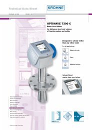
Schild<strong>Type</strong> of approval Certificate number Date <strong>Type</strong> of protection/CommentsFM approval 3012394 2008-11-30 Class I, Zone 0, AEx ia IICClass I, II, III; Div. 1, Groups A, B, C, D, E, F, G;Class I, Div. 2, Groups A, B, C, D; Class II; <strong>Type</strong> <strong>3730</strong>-33CSA approval 1330129 2009-02-19 Ex ia IIC T6; Class I, Zone 0; Class I, Groups A, B, C, DClass II, Groups E, F, G;Class I, Zone 2; Class I, Div. 2, Groups A, B, C, DClass II, Div. 2, Groups E, F, G; <strong>Type</strong> <strong>3730</strong>-33CCoE A/P/HQ/MH/104/1105 2011-01-27 Ex ia IIC T6, Zone 1; valid until 2016-01-26; <strong>Type</strong> <strong>3730</strong>-31INMETRO 2004EC02CP030 2010-05-15 BR - Ex ia T4...T6; valid until 2012-05-10; <strong>Type</strong> <strong>3730</strong>-31The test certificates are included in the mounting <strong>and</strong> operating instructions or are available on request.Refer to Data Sheet T 8379 EN for EEx d certificates for the <strong>Type</strong> 3770 Field Barrier.<strong>Positioner</strong> attachmentThe <strong>Type</strong> <strong>3730</strong> <strong>Electropneumatic</strong> <strong>Positioner</strong> can be attacheddirectly to the <strong>Type</strong> 3277 Actuator over a connection block. Inactuators with fail-safe action “Actuator stem extends” <strong>and</strong><strong>Type</strong> 3277-5 Actuator (120 cm²), the signal pressure is routedover an internal bore in the actuator yoke to the actuator. Inactuators with fail-safe action “Actuator stem retracts” <strong>and</strong> inactuators with effective diaphragm areas of 240 cm² or larger,the signal pressure is routed to the actuator over ready-madeexternal piping.Using a bracket, the positioner can also be attached accordingto IEC 60534-6-1 (NAMUR recommendation). The positionercan be mounted on any side of the control valve.A pair of universal brackets is used for the attachment to<strong>Type</strong> 3278 Rotary Actuators or other rotary actuatorsaccording to VDI/VDE 3845. The rotary motion of the actuatoris transferred to the positioner over a coupling wheel.Dimensions in mmDirect attachment210M 20x1.540External position sensor287070345816428Output (38) Supply (9)8680146 T 8384-2/3 EN
NAMUR attachmentPressure gauge bracketG ¼ or ¼ NPTor connecting plateLeverS = 17 mmM = 50 mmL = 100 mmXL = 200 mm7046581534Output Y 1Supply (9)908050794959801301505852 Output Y 1Output Y 2Output Y 2<strong>Type</strong> 3710 ReversingAmplifier (optional)164Heavy-duty version52Output Y 1Supply (9)Output Y 1Output Y 2Connecting plateG ¼ or ¼ NPT865680Attachment to rotary actuatorsVDI/VDE 3865 (Sept. 2010)Fixing level 1Size AA1 to AA4Light versionConnecting plateG ¼ or ¼ NPTMounting unitCrNiMo steel bracket3086Ø 10180130166Output Y 2<strong>Type</strong> 3710 ReversingAmplifier (optional)7 T 8384-2/3 EN
Article code<strong>Positioner</strong> <strong>Type</strong> <strong>3730</strong>- x x x x x x 0 x x 0 x 0 0 x 0 x xWith LCD <strong>and</strong> autotune, 4 to 20 mA reference variable2 software limit switches, one fault alarm contact 2With LCD <strong>and</strong> autotune, HART ® communication, 4 to 20 mA,2 software limit switches, one fault alarm contact 3Explosion protectionWithout 0II 2 G EEx ia IIC T6 <strong>and</strong>II 2 D IP 65 T 80 °C acc. to ATEX 1CSA/FM intrinsically safe/non incendive 3II 3 G EEx nA/nL II T6 <strong>and</strong> II 3D IP 65 T 80 °C 8Additional equipmentInductive limit switchWithout 0SJ2-SNSJ2-S1N12Solenoid valveWithout 0With, 24 V DC 4Position transmitterWithout 0With 1 0External position sensorWithout 0With 0 1 0Binary inputWithout 0With 0 2DiagnosticsEXPERTplus 4Housing materialAluminum (st<strong>and</strong>ard) 0Stainless steel 1.4581 0 1Special applicationNone 0Device completely free of paint-impairing substances 1Exhaust air port with ¼-18 NPT thread, back of housing sealed 2Special versionNone 0 0IECEx 1 1 2GOST approval Ex ia 1 1 4GOST approval Ex nA/nL 8 2 0Ordering text<strong>Type</strong> <strong>3730</strong>-x... <strong>Positioner</strong>– Without pneumatic connecting rail (only for direct attachmentto <strong>Type</strong> 3277 Actuator)– With pneumatic connecting rail ISO 228/1-G ¼– With pneumatic connecting rail ¼-18 NPT– Without/with pressure gauge up to max. 6 bar– Additional cover label with list of parameters <strong>and</strong> operatinginstructions in English/Spanish or English/French (st<strong>and</strong>ardversion in German/English)– Attachment to <strong>Type</strong> 3277 Actuator (120 to 700 cm²)– Attachment according to IEC 60534-6-1 (NAMUR)Travel: ... mm; if applicable, stem diameter: ... mm– Attachment to <strong>Type</strong> 3278 Rotary Actuator (160/320 cm²),mounting unit with CrNiMo steel bracket or heavy-dutyattachment– Attachment to rotary actuators acc. to VDI/VDE 3845,mounting unit with CrNiMo steel bracket or heavy-duty attachment– Pneumatic reversing amplifier for double-acting actuatorswith connection acc. to ISO 228/1 - G ¼ or ¼-18 NPT– Adapter M20 x 1.5 to ½ NPT– Metal cable gl<strong>and</strong>– Special version with CrNiMo steel housingSAMSON AG · MESS- UND REGELTECHNIKWeismüllerstraße 3 · 60314 Frankfurt am Main · GermanyPhone: +49 69 4009-0 · Fax. +49 069 4009-1507Internet: http://www.samson.deT 8384-2/3 EN2012-02
![[MI 019-120] I/A Series Mass Flowtubes Models CFS20 ... - Invensys](https://img.yumpu.com/48832334/1/190x245/mi-019-120-i-a-series-mass-flowtubes-models-cfs20-invensys.jpg?quality=85)