Honeywell ST 3000 Smart Pressure - Lesman Instrument Company
Honeywell ST 3000 Smart Pressure - Lesman Instrument Company
Honeywell ST 3000 Smart Pressure - Lesman Instrument Company
- No tags were found...

You also want an ePaper? Increase the reach of your titles
YUMPU automatically turns print PDFs into web optimized ePapers that Google loves.
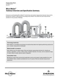
<strong>ST</strong> <strong>3000</strong> <strong>Smart</strong> <strong>Pressure</strong> TransmitterSeries 900 Differential <strong>Pressure</strong> Models<strong>ST</strong>D924 0 to 400 inH2O 0 to 1,000 mbar<strong>ST</strong>D930 0 to 100 psi 0 to 7,000 mbar<strong>ST</strong>D974 0 to <strong>3000</strong> psi 0 to 210,000 mbarIntroduction34-<strong>ST</strong>-03-657/04Specification andModel SelectionGuideIn 1983, <strong>Honeywell</strong> introduced the first<strong>Smart</strong> <strong>Pressure</strong> Transmitter― the <strong>ST</strong><strong>3000</strong> ® . In 1989, <strong>Honeywell</strong> launchedthe first all digital, bi-directional protocolfor smart field devices. Today, its<strong>ST</strong> <strong>3000</strong> Series 900 Differential<strong>Pressure</strong> Transmitters continue to bringproven “smart” technology to a widespectrum of pressure measurementapplications, from furnace combustionairflow rate to hydrostatic tank gauging.The <strong>ST</strong> <strong>3000</strong> S900 Differential<strong>Pressure</strong> Transmitter can be used withany primary flow element to provideproven, repeatable flow measurement.All <strong>ST</strong> <strong>3000</strong> transmitters can provide a4-20 mA output, <strong>Honeywell</strong> DigitallyEnhanced (DE) output, HART * output,or FOUNDATION Fieldbus output.When digitally integrated with<strong>Honeywell</strong>’s Process KnowledgeSystem, EXPERION PKS,<strong>ST</strong> <strong>3000</strong> instruments provide a moreaccurate process variable as well asadvanced diagnostics.<strong>Honeywell</strong>’s cost-effective <strong>ST</strong> <strong>3000</strong>S900 transmitters lead the industry inreliability and stability:• Stability = +/-0.01% per year• Reliability = 470 years MTBFFigure 1—Series 900 Differential <strong>Pressure</strong> Transmitters feature provenpiezoresistive sensor technology.The devices provide comprehensive self-diagnostics to help usersmaintain high uptime, meet regulatory requirements, and attain highquality standards. S900 transmitters allow smart performance atanalog prices. Accurate, reliable and stable, Series 900 transmittersoffer greater turndown ratio than conventional transmitters."<strong>Honeywell</strong> transmitters operating in the digital mode using<strong>Honeywell</strong>'s Digitally Enhanced (DE) protocol make diagnosticsavailable right at the control system's human interface. Equallyimportant, transmitter status information is continuously displayed toalert the operator immediately of a fault condition. Because theprocess variable (PV) status transmission precedes the PV value, weare guaranteed that a bad PV is not used in a control algorithm. Inaddition, bi-directional communication provides for remote transmitterconfiguration directly from the human interface, enabling managementof the complete loop.”Maureen Atchison, DuPontSite Electrical & <strong>Instrument</strong>ation Leader
34-<strong>ST</strong>-03-65Page 2DescriptionThe <strong>ST</strong> <strong>3000</strong> transmitter can replace any 4 to 20 mA output transmitter inuse today and operates over a standard two-wire system.The measuring means is a piezoresistive sensor, which actually containsthree sensors in one. It contains a differential pressure sensor, atemperature sensor, and a static pressure sensor.Microprocessor-based electronics provide higher span-turndown ratio,improved temperature and pressure compensation, and improvedaccuracy.The transmitter’s meter body and electronics housing resist shock,vibration, corrosion, and moisture. The electronics housing contains acompartment for the single-board electronics, which is isolated from anintegral junction box. The single-board electronics is replaceable andinterchangeable with any other <strong>ST</strong> <strong>3000</strong> Series 100 or Series 900 modeltransmitter.Like other <strong>Honeywell</strong> transmitters, the <strong>ST</strong> <strong>3000</strong> features two-waycommunication between the operator and the transmitter through our<strong>Smart</strong> Field Configurator (SFC). You can connect the SFC anywhere thatyou can access the transmitter signal lines.The SCT <strong>3000</strong> <strong>Smart</strong>line ® Configuration Toolkit provides an easy way toconfigure instruments using a personal computer. The toolkit enablesconfiguration of devices before shipping or installation. The SCT <strong>3000</strong> canoperate in the offline mode to configure an unlimited number of devices.The database can then be loaded downline during commissioning.Features• Choice of linear or squareroot output conformity is asimple configuration selection.• Direct digital integration withExperion PKS and othercontrol systems provides localmeasurement accuracy to thesystem level without addingtypical A/D and D/A converterinaccuracies.• Unique piezoresistive sensorautomatically compensatesinput for temperature andstatic pressure.Added “smart”features include configuringlower and upper rangevalues, simulating accurateanalog output, and selectingpreprogrammed engineeringunits for display.• <strong>Smart</strong> transmitter capabilitieswith local or remoteinterfacing means significantmanpower efficiencyimprovements incommissioning, start-up, andongoing maintenancefunctions.
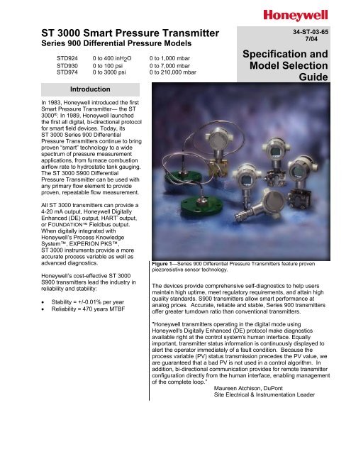
34-<strong>ST</strong>-03-65Page 3SpecificationsOperating Conditions – All ModelsParameterReferenceCondition(at zero static)Rated Condition Operative Limits Transportation andStorage°C °F °C °F °C °F °C °FAmbient Temperature 25 ±1 77 ±2 -40 to 85 -40 to 185 -40 to 85 -40 to 185 -55 to 125 -67 to 257Meter Body Temperature 25 ±1 77 ±2 -40 to 110* -40 to 230* -40 to 125 -40 to 257 -55 to 125 -67 to 257Humidity %RH 10 to 55 0 to 100 0 to 100 0 to 100Vacuum Region - Minimum<strong>Pressure</strong>mmHg absoluteinH2O absoluteAtmosphericAtmospheric25132 (short term **)1 (short term **)Supply Voltage, Current,and Load ResistanceMaximum AllowableWorking <strong>Pressure</strong> (MAWP)(<strong>ST</strong> <strong>3000</strong> products are rated toMaximum Allowable Working<strong>Pressure</strong>. MAWP depends onApproval Agency and transmittermaterials of construction.)Voltage Range: 10.8 to 42.4 Vdc at terminalsCurrent Range: 3.0 to 21.8 mALoad Resistance: 0 to 1440 ohms (as shown in Figure 2)***<strong>ST</strong>D924-AXX, BXX, EXX, FXX, JXX = <strong>3000</strong> psi, 210 bar°<strong>ST</strong>D924-CXX, DXX, GXX, HXX, KXX, LXX = 4500 psi, 310 bar***<strong>ST</strong>D930-AXX, BXX, EXX, FXX, JXX = <strong>3000</strong> psi, 210 bar°<strong>ST</strong>D930-CXX, DXX, GXX, HXX, KXX, LXX = 4500 psi, 310 bar°<strong>ST</strong>D974 = 4500 psi, 310 barStatic <strong>Pressure</strong> Limit = Maximum Allowable Working <strong>Pressure</strong> (MAWP) = OverpressureLimit* For CTFE fill fluid, the rating is –15 to 70°C (5 to 158°F). ** Short term equals 2 hours at 70°C (158°F). ***Static <strong>Pressure</strong> is de-rated to2000 psi (140 bar) for temperatures below –15°C (5°F). °MAWP applies for temperature range –40 to 125 deg. C. However, Static <strong>Pressure</strong>Limit is de-rated to <strong>3000</strong> psi from –26 deg C. to –40 deg. C. Consult factory for MAWP of <strong>ST</strong> <strong>3000</strong> transmitters with CSA approval.14401200LoopResistance(ohms)800650450250NOTE: A minimum of 250 ohmsof loop resistance is necessaryto support communications.Loop resistance equals barrierresistance plus wire resistanceplus receiver resistance.= Operating Area0 10.8 16.28 20.63 25 28.3 37.0 42.4Operating Voltage (Vdc)21012Figure 2—Supply voltage and loop resistance chart
34-<strong>ST</strong>-03-65Page 4Performance Under Rated Conditions* - Model <strong>ST</strong>D924 (0 to 400 inH 2 O/1000 mbar)ParameterUpper Range LimitMinimum SpaninH2OmbarinH2OmbarTurndown Ratio 40 to 1Zero Elevation and SuppressionAccuracy (Reference – Includescombined effects of linearity,hysteresis, and repeatability)• Accuracy includes residual errorafter averaging successivereadings.• For FOUNDATION Fieldbus useDigital Mode specifications. ForHART use Analog Modespecifications.Zero Temperature Effect per28°C (50°F)Combined Zero and SpanTemperature Effect per 28°C(50°F)Zero Static <strong>Pressure</strong> Effect per1000 psi (70 bar)Combined Zero and Span Static<strong>Pressure</strong> Effect per 1000 psi (70bar)StabilityDescription400 (39.2°F/4°C is standard reference temperature for inH2O range.)100010 Note: Recommended minimum span in square root mode is 20 inH2O (50 mbar).25–5 to +100% URL.In Analog Mode: ±0.075% of calibrated span or upper range value (URV), whicheveris greater, terminal based.For URV below reference point (25 inH2O), accuracy equals:25 inH2O±0.025 + 0.05 ⎛ ⎝ span inH2O or ±0.025 + 0.05 62 ( span mbar)in % span⎞⎠In Digital Mode: ±0.0625% of calibrated span or upper range value (URV),whichever is greater, terminal based.For URV below reference point (25 inH2O), accuracy equals:25 inH2O±0.0125 + 0.05 ⎛ ⎞ ⎝ span inH2O⎠or ±0.0125 + 0.05 62 ( span mbar)in % spanIn Analog Mode: ±0.1625% of span.For URV below reference point (50 inH2O), effect equals:50 inH2O±0.0125 + 0.15 ⎛ ⎝ span inH2O or ±0.0125 + 0.15 125 ( span mbar)in % span⎞⎠In Digital Mode: ±0.15% of span.For URV below reference point (50 inH2O), effect equals:50 inH2O±0.15 ⎛ ⎞ ⎝ span inH2O⎠or ±0.15 125 ( span mbar)in % spanIn Analog Mode: ±0.25% of span.For URV below reference point (50 inH2O), effect equals:50 inH2O±0.10 + 0.15 ⎛ ⎝ span inH2O or ±0.10 + 0.15 125 ( span mbar)in % span⎞⎠In Digital Mode: ±0.225% of span.For URV below reference point (50 inH2O), effect equals:50 inH2O±0.075 + 0.15 ⎛ ⎝ span inH2O or ±0.075 + 0.15 125 ( span mbar)in % span⎞⎠±0.1625% of span.For URV below reference point (50 inH2O), effect equals:50 inH2O±0.0125 + 0.15 ⎛ ⎝ span inH2O or ±0.0125 + 0.15 125 ( span mbar)in % span⎞⎠⎞⎠±0.30% of span.For URV below reference point (50 inH2O), effect equals:50 inH2O±0.15 + 0.15 ⎛ ⎝ span inH2O or ±0.15 + 0.15 125 ( span mbar)in % span±0.015% of URL per year* Performance specifications are based on reference conditions of 25°C (77°F), zero (0) static pressure, 10 to 55% RH, and316L Stainless Steel barrier diaphragm.
Performance Under Rated Conditions* - Model <strong>ST</strong>D930 (0 to 100 psi/7000 mbar)ParameterUpper Range LimitMinimum Spanpsibarpsibar100750.35Turndown Ratio 20 to 1Zero Elevation and SuppressionAccuracy (Reference – Includescombined effects of linearity,hysteresis, and repeatability)••Zero Temperature Effect per28°C (50°F)Combined Zero and SpanTemperature Effect per 28°C(50°F)Zero Static <strong>Pressure</strong> Effect per1000 psi (70 bar)Combined Zero and Span Static<strong>Pressure</strong> Effect per 1000 psi (70bar)Stability–5 to +100% URL.Description34-<strong>ST</strong>-03-65Page 5In Analog Mode: ±0.075% of calibrated span or upper range value (URV), whicheveris greater, terminal based.For URV below reference point (20 psi), accuracy equals:±0.025 + 0.05 (20 psi) span psior ±0.025 + 0.05 (1.4 barspan bar )in % spanIn Digital Mode: ±0.0625% of calibrated span or upper range value (URV),whichever is greater, terminal based.For URV below reference point (20 psi), accuracy equals:±0.0125 + 0.05 (20 psi) span psior ±0.0125 + 0.05 (1.4 barspan bar )In Analog Mode: ±0.1625% of span.For URV below reference point (30 psi), effect equals:±0.0125 + 0.15 (30 psi) span psior ±0.0125 + 0.15 (2 barspan bar )In Digital Mode: ±0.15% of span.For URV below reference point (30 psi), effect equals:±0.15 (30 psi) span psior ±0.15 (2 barspan bar )in % spanIn Analog Mode: ±0.25% of span.For URV below reference point (30 psi), effect equals:±0.10 + 0.15 (30 psi) span psior ±0.10 + 0.15 (2 barspan bar )In Digital Mode: ±0.225% of span.For URV below reference point (30 psi), effect equals:±0.075 + 0.15 (30 psi) span psior ±0.075 + 0.15 (2 barspan bar )±0.1625% of span.For URV below reference point (30 psi), effect equals:±0.0125 + 0.15 (30 psi) span psior ±0.0125 + 0.15 (2 barspan bar )±0.30% of span.For URV below reference point (30 psi), effect equals:±0.15 + 0.15 (30 psi) span psi±0.04% of URL per yearor ±0.15 + 0.15 (2 barspan bar )in % spanin % spanin % spanin % spanin % spanin % span* Performance specifications are based on reference conditions of 25°C (77°F), zero (0) static pressure, 10 to 55% RH, and316L Stainless Steel barrier diaphragm.
34-<strong>ST</strong>-03-65Page 6Performance Under Rated Conditions* - Model <strong>ST</strong>D974 (0 to <strong>3000</strong> psi/210 bar)ParameterUpper Range LimitMinimum Spanpsibarpsibar<strong>3000</strong>2101007Turndown Ratio 30 to 1Zero Elevation and SuppressionAccuracy (Reference – Includescombined effects of linearity,hysteresis, and repeatability)• Accuracy includes residual errorafter averaging successivereadings.• For FOUNDATION Fieldbus useDigital Mode specifications. ForHART use Analog Modespecifications.Zero Temperature Effect per28°C (50°F)Combined Zero and SpanTemperature Effect per 28°C(50°F)Zero Static <strong>Pressure</strong> Effect per1000 psi (70 bar)Combined Zero and Span Static<strong>Pressure</strong> Effect per 1000 psi (70bar)–0.6 and +100% URL.DescriptionIn Analog Mode: ±0.2% of calibrated span or upper range value (URV), whichever isgreater, terminal based.For URV below reference point (300 psi), accuracy equals:±0.05 + 0.15 (300 psi) span psior ±0.05+ 0.15 (21 barspan bar )in % spanIn Digital Mode: ±0.175% of calibrated span or upper range value (URV), whicheveris greater, terminal based.For URV below reference point (300 psi), accuracy equals:±0.025 + 0.15 (300 psi) span psior ±0.025+ 0.15 (21 barspan bar )In Analog Mode: ±0.2125% of span.For URV below reference point (500 psi), effect equals:±0.0125 + 0.20 (500 psi) span psior ±0.0125 + 0.20 (35 barspan bar )In Digital Mode: ±0.20% of span.For URV below reference point (500 psi), effect equals:±0.20 (500 psi) span psior ±0.20 (35 barspan bar )in % spanIn Analog Mode: ±0.325% of span.For URV below reference point (500 psi), effect equals:±0.125 + 0.20 (500 psi) span psior ±0.125 + 0.20 (35 barspan bar )In Digital Mode: ±0.30% of span.For URV below reference point (500 psi), effect equals:±0.10 + 0.20 (500 psi) span psior ±0.10 + 0.20 (35 barspan bar )±0.1625% of span.For URV below reference point (500 psi), effect equals:±0.0125 + 0.15 (500 psi) span psior ±0.0125 + 0.15 (35 barspan bar )±0.30% of span.For URV below reference point (500 psi), effect equals:±0.15 + 0.15 (500 psi) span psior ±0.15 + 0.15 (35 barspan bar )in % spanin % spanin % spanin % spanin % spanin % spanStability±0.03% of URL per year* Performance specifications are based on reference conditions of 25°C (77°F), zero (0) static pressure, 10 to 55% RH, and316L Stainless Steel barrier diaphragm.
34-<strong>ST</strong>-03-65Page 8<strong>Pressure</strong> Equipment Directive(97/23/EC)The <strong>ST</strong> <strong>3000</strong> pressure transmitters listed in this Specification have no pressurizedinternal volume or have a pressurized internal volume rated less than 1,000 bar(14,500 psig) and/or have a maximum volume of less than 0.1 liter. Therefore, thesetransmitters are either; not subject to the essential requirements of the directive97/23/EC (PED, Annex 1) and shall not have the CE mark, or the manufacturer hasthe free choice of a module when the CE mark is required for pressures > 200 bar(2,900 psig).NOTE: <strong>Pressure</strong> transmitters that are part of safety equipment for the protection of piping (systems) or vessel(s) fromexceeding allowable pressure limits, (equipment with safety functions in accordance with <strong>Pressure</strong> Equipment Directive97/23/EC article 1, 2.1.3), require separate examination.
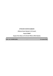
34-<strong>ST</strong>-03-65Page 924264Figure 3—Examples of typical mounting positions
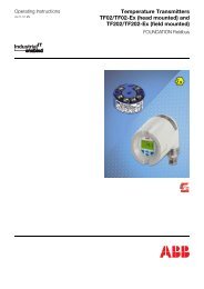
34-<strong>ST</strong>-03-65Page 10Reference Dimensions: millimetersinchesWith<strong>Smart</strong>meterRemovalClearancefor All Caps45.71.882.93.2653.12.09Withoutmeter94.93.7465.12.56Withoutmeter3.60.14Plug1355.3255.32.1823.5.9252148.43OptionalexternalgroundRotationalLockOptionalMeters125.24.93672.64Optional Adapterfor 1/2-inch NPTSee Detail "A"32.51.2893.63.6953.92.121295.08Detail A53.92.12High <strong>Pressure</strong>Connection1/2-inch NPT53.92.121.50.06Low <strong>Pressure</strong>Connection1/2-inch NPT24258Figure 4—Typical models <strong>ST</strong>D924 and <strong>ST</strong>D930-A, B, E, F, J (SS, Hastelloy C) mounting dimensions forreference.
34-<strong>ST</strong>-03-65Page 11Reference Dimensions: millimetersinchesWith <strong>Smart</strong> meterRemovalClearancefor All Caps45.71.882.93.2653.12.09Withoutmeter94.93.7465.12.56WithoutmeterWithAnalogmeter1355.323.60.14 Plug23.5.92555.32.18Optionalmeters266.610.5Optionalexternalground168.86.65Rotational lock853.35SQOptional Adapter for1/2-inch NPTSee Detail "A"32.51.28Plug1003.94Detail A53.92.1253.92.12121.44.78High <strong>Pressure</strong>Connection1/2-inch NPT53.92.121.50.06Low <strong>Pressure</strong>Connection1/2-inch NPT24259Figure 5—Typical models <strong>ST</strong>D924 and <strong>ST</strong>D930-C, D, G, H, K, L (Monel, Tantalum), and model <strong>ST</strong>D974mounting dimensions for reference
34-<strong>ST</strong>-03-65Page 12OptionsOrdering InformationMounting BracketThe angle mounting bracket isavailable in either zinc-platedcarbon steel or stainless steel andis suitable for horizontal or verticalmounting on a two inch (50millimeter) pipe, as well as wallmounting. An optional flatmounting bracket is also availablein carbon steel for two inch (50millimeter) pipe mounting.Indicating Meter(ME and SM Options)Two integral meter options areavailable. An analog meter (optionME) is available with a 0 to 100%linear scale. The <strong>Smart</strong> Meter(option SM) provides an LCDdisplay for both analog and digitaloutput and can be configured todisplay pressure in pre-selectedengineering units.Lightning Protection(Option LP)A terminal block is available withcircuitry that protects thetransmitter from transient surgesinduced by nearby lightningstrikes.HART Protocol Compatibility(Option HC)An optional electronics module isavailable for the <strong>ST</strong> <strong>3000</strong> thatprovides HART Protocolcompatibility. Transmitters with theHART Option are compatible withthe AMS System. (Contact yourAMS Supplier if an upgrade isrequired.)Indicator Configuration(Option CI)Provides custom configuration of<strong>Smart</strong> Meters.Tagging (Option TG)Up to 30 characters can be addedon the stainless steel nameplatemounted on the transmitter’selectronics housing at no extra cost.Note that a separate nameplate onthe meter body contains the serialnumber and body-related data. Astainless steel wired on tag withadditional data of up to 4 lines of 28characters is also available. Thenumber of characters for taggingincludes spaces.Transmitter Configuration(Option TC)The factory can configure thetransmitter linear/square rootextraction, damping time, LRV,URV and mode (analog/digital) andenter an ID tag of up to eightcharacters and scratchpadinformation as specified.Custom Calibration and ID inMemory (Option CC)The factory can calibrate any rangewithin the scope of the transmitter’srange and enter an ID tag of up toeight characters in the transmitter’smemory.FOUNDATION Fieldbus(Option FF)Equips transmitter with FFprotocol for use in 31.25 kbit/sFF networks. See document34-<strong>ST</strong>-03-72 for additionalinformation on <strong>ST</strong> <strong>3000</strong>Fieldbus transmitters.Contact your nearest <strong>Honeywell</strong> salesoffice, orIn the U.S.:<strong>Honeywell</strong>Industrial Automation & Control16404 North Black Canyon Hwy.Phoenix, AZ 850531-800-288-7491In Canada:The <strong>Honeywell</strong> Centre155 Gordon Baker Rd.North York, Ontario M2H 3N71-800-461-0013In Latin America:<strong>Honeywell</strong> Inc.480 Sawgrass Corporate Parkway,Suite 200Sunrise, FL 33325(954) 845-2600In Europe and Africa:<strong>Honeywell</strong> S. A.Avenue du Bourget 11140 Brussels, BelgiumIn Eastern Europe:<strong>Honeywell</strong> Praha,s.r.o. Budejovicka 1140 21 Prague 4,Czech RepublicIn the Middle East:<strong>Honeywell</strong> Middle East Ltd.Khalifa Street,Sheikh Faisal BuildingAbu Dhabi, U. A. E.In Asia:<strong>Honeywell</strong> Asia Pacific Inc.<strong>Honeywell</strong> Building,17 Changi Business Park Central 1Singapore 486073Republic of SingaporeIn the Pacific:<strong>Honeywell</strong> Pty Ltd.5 Thomas Holt DriveNorth Ryde NSW Australia 2113(61 2) 9353 7000In Japan:<strong>Honeywell</strong> K.K.14-6 Shibaura 1-chromeMinato-ku, Tokyo, Japan 105-0023Specifications are subject to change without notice.(Note that specifications may differ slightly for transmitters manufactured beforeOctober 30, 1995.)Or, visit <strong>Honeywell</strong> on the World WideWeb at: http://www.honeywell.com
34-<strong>ST</strong>-03-65Page 1334-<strong>ST</strong>-16-24 Issue 28<strong>Honeywell</strong> Confidential & ProprietaryInstructionsSelect the desired Key Number. The arrow to the right marks the selection available.Make one selection from each table, I and II, using the column below the proper arrow.Select as many Table III options as desired (if no options or approvals are desired, specify 9X).A (•) denotes unrestricted availability. A letter denotes restricted availability.Restrictions follow Table IV.Key Number I II III (Optional) IV_ _ _ _ _ _ - _ _ _ - _ _ _ _ _ - _ _, _ _ _ _ + XXXXKEY NUMBER Selection AvailabilitySpan0-10" to 0-400" H 2 O/0-25 to 0-1000 mbar <strong>ST</strong>D924Body Rating: <strong>3000</strong> psi (210 bar)0-5 to 0-100 psi/0-0.34 to 0-7 bar <strong>ST</strong>D930Body Rating: <strong>3000</strong> psi (210 bar)0-100 to 0-<strong>3000</strong> psi/0-7 to 0-210 bar <strong>ST</strong>D974Body Rating: 4500 psi (315 bar)TABLE I - METER BODYWetted Vent/DrainProcess Heads Valves ** Barrierand PlugsDiaphragmsCarbon Steel * 316 St. St. 316 LSS A _ _ • • •Carbon Steel * 316 St. St. Hastelloy C B _ _ • • •Carbon Steel * 316 St. St. Monel C _ _ • •Material Carbon Steel * 316 St. St. Tantalum D _ _ • •of 316 St. St. 316 St. St. 316 LSS E _ _ • • •Construction 316 St. St. 316 St. St. Hastelloy C F _ _ • • •316 St. St. 316 St. St. Monel G _ _ • •316 St. St. 316 St. St. Tantalum H _ _ • •Hastelloy C Hastelloy C Hastelloy C J _ _ • • •Hastelloy C Hastelloy C Tantalum K _ _ • •Monel Monel Monel L _ _ • •Fill Fluid Silicone _ 1 _ • • •CTFE _ 2 _ • • •Process Head 1/4" NPT _ _ A • • •Configuration 1/2" NPT with Adapter (on 1/4" NPT Head) _ _ H t t tTABLE IINo Selection 00000 • • •* Carbon Steel heads are zinc-plated. Not recommended for water service due to hydrogen migration.Use Stainless Steel heads.** Vent/Drains are Teflon coated for lubricity.
34-<strong>ST</strong>-03-65Page 14<strong>ST</strong>D9TABLE III - OPTIONS Selection 24 30 74None 00 • • •Communication ProtocolsHART ® Protocol Compatible Electronics HC e e eFOUNDATION Fieldbus Communications FF r r rbIndicating Meter OptionsAnalog Meter (0-100 Even 0-10 Square Root) ME • • •<strong>Smart</strong> Meter SM • • •bCustom Configuration of <strong>Smart</strong> Meter CI m m mLocal Zero LZ x x xLocal Zero and Span ZS s s sbTransmitter Housing & Electronics OptionsLightning Protection LP • • •Custom Calibration and I.D. in Memory CC • • •Transmitter Configuration TC • • •Write Protection WP • • •316 <strong>ST</strong>.<strong>ST</strong>. Electronics Housing - with M20 Conduit Connections SH n n n1/2" NPT to M20 316SS Conduit Adapter (BASEEFA EEx d IIC) A1 n n n1/2" NPT to 3/4" NPT 316 SS Conduit Adapter A2 i i ibStainless Steel Housing with M20 to 1/2" NPT 316 SS Conduit A3 i i iAdapter (use for FM and CSA Approvals)Stainless Steel Customer Wired-On Tag TG • • •(4 lines, 28 characters per line, customer supplied information)Stainless Steel Customer Wired-On Tag (blank) TB • • •Low Temperature - -50 o C Ambient Limit LT •End Cap Live Circuit Warning Label in Spanish (only with ATEX 3D) SP a a aEnd Cap Live Circuit Warning Label in Portuguese (only with ATEX 3D) PG a a a bEnd Cap Live Circuit Warning Label in Italian (only with ATEX 3D) TL a a aEnd Cap Live Circuit Warning Label in German (only with ATEX 3D) GE a a aMeter Body Options316 SS Bolts and 316 SS Nuts for Process Heads SS k k •B7M Bolts and Nuts for Process Heads B7 k k • bNACE A286SS Bolts and 304SS Nuts for Process Heads CR • • •316SS Adapter Flange - 1/2" NPT with CS Bolts S2 c c c316SS Adapter Flange - 1/2" NPT with 316SS Bolts S3 k k c316SS Adapter Flange - 1/2" NPT with NACE A286 Bolts S4 k k c316SS Adapter Flange - 1/2" NPT with B7M Bolts S5 k k cHastelloy C Adapter Flange - 1/2" NPT with CS Bolts T2 c c c bHastelloy C Adapter Flange - 1/2" NPT with 316SS Bolts T3 k k cMonel Adapter Flange - 1/2" NPT with CS Bolts V2 c c cMonel Adapter Flange - 1/2" NPT with 316SS Bolts V3 k k c316SS Blind Adapter Flange with CS Bolts B3 k k c316SS Blind Adapter Flange with 316SS Bolts B4 k k c316SS Blind Adapter Flange with NACE A286 Bolts B5 k k c316SS Blind Adapter Flange with B7M Bolts B6 k k c bSide Vent/Drain (End Vent Drain is standard) SV • • •SS Center Vent Drain and Bushing CV • •Blind DIN SS Flanges Mounted with NACE Bolts B2 d dModified DIN Process Heads - 316SS DN w wViton Process Head Gaskets (adapter gaskets ordered separately) VT z z •Viton Flange Adaptor Gaskets VF k k •Transmitter Mounting Brackets OptionsMounting Bracket - Carbon Steel MB • • •Mounting Bracket - <strong>ST</strong>. <strong>ST</strong>. SB • • • bFlat Mounting Bracket - Carbon Steel FB • • •
34-<strong>ST</strong>-03-65Page 15<strong>ST</strong>D9TABLE III - OPTIONS (continued) Selection 24 30 74Services/Certificates/Marine Type Approvals OptionsClean Transmitter for Oxygen or Chlorine Service with Certificate 0X j j jOver-<strong>Pressure</strong> Leak Test with F3392 Certificate TP • • •Calibration Test Report and Certificate of Conformance (F3399) F1 • • •Certificate of Conformance (F3391) F3 • • •Certificate of Origin (F0195) F5 • • •FMEDA (SIL) Certificate F6 • • •NACE Certificate (F0198) F7 o o oMarine Type Approvals (DNV, ABS, BV & LR) MT 2 2 2Warranty OptionsAdditional Warranty - 1 year W1 • • •Additional Warranty - 2 years W2 • • •Additional Warranty - 3 years W3 • • •Additional Warranty - 4 years W4 • • •bbTABLE III - OPTIONS (continued) Selection 24 30 74ApprovalBody Approval Type Location or ClassificationNo hazardous location approvals 9X • • •Explosion Proof Class I, Div. 1, Groups A,B,C,DFactory Dust Ignition Proof Class II, III Div. 1, Groups E,F,GMutual Non-Incendive Class I, Div. 2, Groups A,B,C,D 1C • • •Intrinsically Safe Class I, II, III, Div. 1, GroupsA,B,C,D,E,F,GExplosion Proof Class I, Div. 1, Groups B,C,DCSA Dust Ignition Proof Class II, III, Div. 1, Groups E,F,G 2J • • •Intrinsically Safe Class I, II, III, Div. 1, Groups bA,B,C,D,E,F,GSA Intrinsically Safe Ex ia IIC T4 4G • • •(Australia) Non-Sparking Ex n IIC T6 (T4 with SM option)Intrinsically Safe, Zone Ex II 1G EEx ia IIC T4, T5,T6 3S • • •0/1Flameproof, Zone 1 Ex II 2G EEx d IIC T5, T6, 3D • f •Enclosure IP 66/67Non-Sparking, Zone 2 Ex II 3G EEx nA, IIC T6 3N • • •ATEX* (<strong>Honeywell</strong>). Enclosure IP 66/67Multiple Marking** Ex II 1 G EEx ia IIC T4, T5, T6Int. Safe, Zone 0/1, or Ex II 2 G EEx d IIC T5, T6 3H • • •Flameproof, Zone 1, or Ex II 3 G EEx nA, IIC T6 (<strong>Honeywell</strong>)Non-Sparking, Zone 2 Enclosure IP 66/67INMETRO Flameproof, Zone 1 Ex d IIC T5 6D • • •(Brazil)*See ATEX installation requirements in the <strong>ST</strong> <strong>3000</strong> User's Manual<strong>ST</strong>D9**The user must determine the type of protection required for installation of the equipment. The user shall thencheck the box [] adjacent to the type of protection used on the equipment certification nameplate. Once a typeof protection has been checked on the nameplate, the equipment shall not then be reinstalled using any of theother certification types.
34-<strong>ST</strong>-03-65Page 16TABLE IVFactory Identification XXXX • • •RE<strong>ST</strong>RICTIONSRestriction Available Only With Not Available WithLetter Table Selection Table Selectiona III3D or 3HbSelect only one option from this groupc I _ _ Hd I E _ _, F _ _IIIDNe III 4Gg I K _ _, L _ _includes side ventno price addh I C _ _, G _ _, L _ _i III1C or 2Jj I _ 2 _k I C_H, D_H, G_H, H_H, K_H, L_Hm III SMn III 1C, 2Jo III CR,S4,B5r III TC, ME, 4G,3Ss III FF, MEt III Select from Table III S2,S3,S4III S5,T2,T3,V2,V3,B3,B4,B5,B6w I E _ A, F _ A III SVx III FF, SMy I J_ _, includesside vent, no price addIIIDNz I B _ _, F _ _, J _ _,2 IIIFBNote:See <strong>ST</strong>-83 for Published Specials with pricing.See <strong>ST</strong>-89 and User's Manual for part numbers.See <strong>ST</strong>-OE-9 for OMS Order Entry Information including TC, manuals,certificates, drawings and SPINS.See <strong>ST</strong>-OD-1 for tagging, ID, Transmitter Configuration (TC) andcalibration including factory default values.To request a quotation for a non-published "special", fax RFQ to MarketingApplications.
34-<strong>ST</strong>-03-65Page 17This page intentionally blank<strong>ST</strong> <strong>3000</strong>® is a registered trademark of <strong>Honeywell</strong> International Inc.HART* is a trademark of the Hart Communication Foundation.FOUNDATION is a trademark of the Fieldbus Foundation.Industrial Measurement and Control<strong>Honeywell</strong> International Inc.2500 W. Union Hill DrivePhoenix, Arizona 85027©<strong>Honeywell</strong> International Inc.

![[MI 019-120] I/A Series Mass Flowtubes Models CFS20 ... - Invensys](https://img.yumpu.com/48832334/1/190x245/mi-019-120-i-a-series-mass-flowtubes-models-cfs20-invensys.jpg?quality=85)