Temperature Transmitters TF02/TF02-Ex (head mounted) and ...
Temperature Transmitters TF02/TF02-Ex (head mounted) and ...
Temperature Transmitters TF02/TF02-Ex (head mounted) and ...

You also want an ePaper? Increase the reach of your titles
YUMPU automatically turns print PDFs into web optimized ePapers that Google loves.
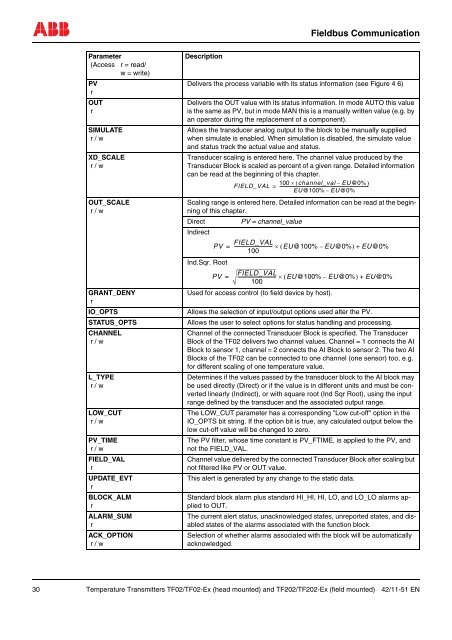
Fieldbus CommunicationParameter(Access r = read/w = write)PVrOUTrSIMULATEr / wXD_SCALEr / wOUT_SCALEr / wGRANT_DENYrIO_OPTSSTATUS_OPTSCHANNELr / wL_TYPEr / wLOW_CUTr / wPV_TIMEr / wFIELD_VALrUPDATE_EVTrBLOCK_ALMrALARM_SUMrACK_OPTIONr / wDescriptionDelivers the process variable with its status information (see Figure 4 6)Delivers the OUT value with its status information. In mode AUTO this valueis the same as PV, but in mode MAN this is a manually written value (e.g. byan operator during the replacement of a component).Allows the transducer analog output to the block to be manually suppliedwhen simulate is enabled. When simulation is disabled, the simulate value<strong>and</strong> status track the actual value <strong>and</strong> status.Transducer scaling is entered here. The channel value produced by theTransducer Block is scaled as percent of a given range. Detailed informationcan be read at the beginning of this chapter.100 × ( channel_val – EU@0% )FIELD_VAL = ---------------------------------------------------------------------------------------EU@100% – EU@0%Scaling range is entered here. Detailed information can be read at the beginningof this chapter.DirectPV = channel_valueIndirectFIELD_VALPV = --------------------------------- × ( EU@100% – EU@0% ) + EU@0%100Ind.Sqr. RootPV =FIELD_VAL--------------------------------- × ( EU@100% – EU@0% ) + EU@0%100Used for access control (to field device by host).Allows the selection of input/output options used alter the PV.Allows the user to select options for status h<strong>and</strong>ling <strong>and</strong> processing.Channel of the connected Transducer Block is specified. The TransducerBlock of the <strong>TF02</strong> delivers two channel values. Channel = 1 connects the AIBlock to sensor 1, channel = 2 connects the AI Block to sensor 2. The two AIBlocks of the <strong>TF02</strong> can be connected to one channel (one sensor) too, e.g.for different scaling of one temperature value.Determines if the values passed by the transducer block to the AI block maybe used directly (Direct) or if the value is in different units <strong>and</strong> must be convertedlinearly (Indirect), or with square root (Ind Sqr Root), using the inputrange defined by the transducer <strong>and</strong> the associated output range.The LOW_CUT parameter has a corresponding "Low cut-off" option in theIO_OPTS bit string. If the option bit is true, any calculated output below thelow cut-off value will be changed to zero.The PV filter, whose time constant is PV_FTIME, is applied to the PV, <strong>and</strong>not the FIELD_VAL.Channel value delivered by the connected Transducer Block after scaling butnot filtered like PV or OUT value.This alert is generated by any change to the static data.St<strong>and</strong>ard block alarm plus st<strong>and</strong>ard HI_HI, HI, LO, <strong>and</strong> LO_LO alarms appliedto OUT.The current alert status, unacknowledged states, unreported states, <strong>and</strong> disabledstates of the alarms associated with the function block.Selection of whether alarms associated with the block will be automaticallyacknowledged.30 <strong>Temperature</strong> <strong>Transmitters</strong> <strong>TF02</strong>/<strong>TF02</strong>-<strong>Ex</strong> (<strong>head</strong> <strong>mounted</strong>) <strong>and</strong> TF202/TF202-<strong>Ex</strong> (field <strong>mounted</strong>) 42/11-51 EN
![[MI 019-120] I/A Series Mass Flowtubes Models CFS20 ... - Invensys](https://img.yumpu.com/48832334/1/190x245/mi-019-120-i-a-series-mass-flowtubes-models-cfs20-invensys.jpg?quality=85)