Friction Stir Welding - ESAB
Friction Stir Welding - ESAB
Friction Stir Welding - ESAB

Create successful ePaper yourself
Turn your PDF publications into a flip-book with our unique Google optimized e-Paper software.
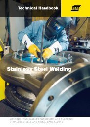
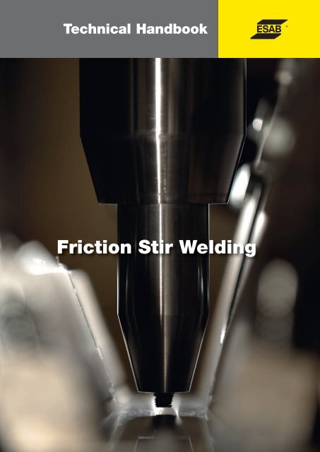
Technical Handbook<strong>Friction</strong> <strong>Stir</strong> <strong>Welding</strong>
Contentspage pageIntroduction 4Process principles 6Weldable alloys 6Process characteristics 7<strong>Welding</strong> parameters 7Tools 7Design principles 8Tools for steels 8Retractable pin tool 8Bobbin tool 10Process speed 10Aluminium 13Application areas 15Aerospace 15Space industry 15Civil aviation 16Aerospace R&D 16Shipbuilding 18Application advances 18Parts and components 19Automotive industry 21Automotive applications 22Tailor welded blanks (TWB´s) 27Superplastic forming 27Extruders and extrusions– with special focus on rolling-stock panels 28Steel and other high-temperature materials 30Application examples 32Case study: Swedish Nuclear 32Case study: Marine Aluminium a.s, Norway 35Equipment 37Full-scale automation forhigh-volume applications 37Modular flexibility for“standard” applications 37Robotised for more complex applications 37Quality and enviromental aspects 39Environmental aspects of <strong>Friction</strong> <strong>Stir</strong> <strong>Welding</strong> 39Less weld-seam preparation 39Fewer resources 39Noise, an underestimated health threat 39Energy saving FSW process 39Less post-treatment and impacton the environment 39<strong>Friction</strong> <strong>Stir</strong> Welded components offerthrough-life environmental gains 40Quality 40Economics 41Example of cost analysis 42Compared to arc welding 44Conclusions 46DISCLAIMERWhilst all reasonable efforts have been made to ensure the accuracy of the information contained inthis handbook at the time of going to press, <strong>ESAB</strong> gives no warranty with regard to its accuracy orcompleteness. It is the responsibility of the reader to check the accuracy of the informationcontained in this handbook, read product labels and equipment instructions and comply with currentregulations. If the reader is in any doubt with regard to the proper use of any technology they shouldcontact the manufacturer or obtain alternative expert advice. <strong>ESAB</strong> accepts no responsibility orliability for any injury, loss or damage incurred as a result of any use or reliance upon the informationcontained in this handbook.3
Process principlesWeldable alloysIn terms of high-temperature materials, FSW has beenproven successful on numerous of alloys and materials,including high-strength steels, stainless steel and titanium.As what is weldable refers to the material by which theMaterial Condition t (mm)Yield strength,Rp0,2 (Mpa)Tensilestrength,Rm (Mpa)Elongation,A5 (%)WeldratioSource2024-T3 FSW 4.0 304 432 7.6 0.87 Biallas G, et. al19992024-T3 FSW 1.6 325 461 11 0.98 Biallas G, et. al2000<strong>Welding</strong> parametersIn providing proper contactand thereby ensuring a highquality weld, the mostimportant control feature iswelding tool is made and how the process is applied thereare really no limits to what can be achieved. Improvementson the existing methods and materials as well as newtechnological development, an expansion is expected.Process characteristicsThe FSW process involves joint formation below the basematerial’s melting temperature. The heat generated in thejoint area is typically about 80-90% of the melting2024-T3 FSW 310 441 16.3 0.9 Magnusson &Källman 20002024-T3 Solution heattreatedand aged2024-T351 Base 6.4 310 430 12302 445 14.5 0.9 Magnusson &Källman 20015083-0 Base 148 298 23.5 TWI5083-0 FSW 141 298 23 1.00 TWI5083-H321 Base 249 336 16.5 TWI5083-H321 FSW 153 305 22.5 0.91 TWI6013-T6 Aged to T6 h253 291 8.3 0.75 Magnusson &Källman 2002down force (Z-axis). Thisguarantees high quality evenwhere tolerance errors in thematerials to be joined mayarise. It also enables robustcontrol during higher weldingspeeds, as the down force willensure the generation offrictional heat to soften thetemperature.6082-T4 Base 149 260 22.9 SAPA profilesABmaterial.With arc welding, calculating heat input is critically6082-T4 FSW 138 244 18.8 0.93 SAPA profilesABWhen using FSW, the followingimportant when preparing welding procedure specifications(WPS) for the production process. With FSW, thetraditional components – current and voltage – are notpresent as the heat input is purely mechanical and therebyreplaced by force, friction, and rotation. Several studies6082-T4 FSW + heattreatment285 310 9.9 1.19 SAPA profilesAB6082-T6 Base 286 301 10.4 TWI6082-T6 FSW 160 254 4.85 0.83 SAPA profilesAB6082-T6 FSW + heattreatment274 300 6.4 1 SAPA profilesABparameters must be controlled:down force, welding speed,the rotation speed of the weldingtool and tilting angle. Onlyfour main parameters need tohave been conducted to identify the way heat is generated7108-T79 Base 295 370 14be mastered, making FSW€and transferred to the joint area. A simplified model isdescribed in the following equation:Q = µωFKin which the heat (Q) is the result of friction (μ), tool rotationspeed (ω) down force (F) and a tool geometry constant (K).The quality of an FSW joint is always superior toconventional fusion-welded joints. A number of propertiessupport this claim, including FSW’s superior fatiguecharacteristics. Figure 3 clearly demonstrates the improvedperformance of FSW compared to a MIG-welded joint onthe selected base material.Figure 2. Brass, as well as mixed copper/aluminium joints,can be friction stir welded. © <strong>ESAB</strong>7108-T79 FSW 210 320 12 0.867108-T79 FSW and aged 245 350 11 0.95 TWI7475- T76 FSW 381 465 12.8 0.92 Magnusson &Källman 20037475- T76 Solution heattreatedand agedTable 1. Collection of tensile test results for various aluminum alloys.ParameterRotation speedTilting angle<strong>Welding</strong> speedDown forceEffects476 512 10 0.97 Magnusson &Källman 2004<strong>Friction</strong>al heat, “stirring”, oxide layer breaking and mixing of material.The appearance of the weld, thinning.Appearance, heat control.<strong>Friction</strong>al heat, maintaining contact conditions.Table 2. Main process parameters in friction stir welding.ideal for mechanised welding.Tools<strong>Welding</strong> tool design is criticalin FSW. Optimising toolgeometry to produce moreheat or achieve more efficient“stirring” offers two mainbenefits: improved breakingand mixing of the oxide layerand more efficient heatgeneration, yielding higherwelding speeds and, of course,Tensile strength is another important quality feature.Table 1 shows a collection of published results from tensilestrength tests.Blue = base material Red = FSW Black = MIGFigure 3. Fatique life evaluation of AA5059.Alloy group Temperature range in °CAluminium alloys 440…550Magnesium alloys 250…350Copper alloys 600…900Carbon and low-alloy steels 650…800Titanium alloys 700…950enhanced quality.The simplest tool can bemachined from an M20 boltwith very little effort. It hasproved feasible to weld thinaluminium plates, even withTable 3. <strong>Welding</strong> temperature range of various alloys.tooling as simple as this,67
although at very slow welding speeds. However, toolmaterials should feature relatively high hardness atelevated temperatures, and should retain thishardness for an extended period. The combinationof tool material and base material is therefore alwayscrucial to the tool’s operational lifetime. Table 3illustrates the forging temperature range of differentalloy groups. Note what useful tools forging tablesare in the FSW context.Figure 4. Pin-tool geometries for FSW tools.Design principlesThe simple pin-shaped, non-profiled tool createsfrictional heat and is very useful if enough downforcecan be applied. Unfortunately, the oxide-layerbreaking characteristics are not very good, and asmaterial thickness is increased, welding heat at thelower part of the joint may be insufficient.With parameter adjustment and tool geometryoptimisation, the oxide-layer could be broken moreeffectively. The need to generate more frictional heatand break the oxide-layer more effectively has beena driving force in tool development for light-metals.In Figure 4 different pin-tools are displayed showingdifferences in shape, size and geometric features, tomatch the needs of specific applications. Toolmaterials for mild and stainless steel have beenadded to the list. Figure 5 illustrates some standardtools trademarked by TWI (The <strong>Welding</strong> Institute).Triflute MX has proven to be a very capablemultipurpose tool for welding all aluminium alloys.Tools for steelsTo apply FSW in steel or other high-temperaturematerials, the difficulty is mainly associated withfinding proper tool material; a material that canwithstand the high temperatures that areexperienced during the process. Resistance to wear(durability) is one important aspect, especially asmany of the intended applications are consideredcritical; hence there can be no traces of the tool leftin the seam. One of the most promising toolmaterials so far is the so called PCBNFigure 5. Some of the basic tool shapes for friction stir welding.© TWI.(polycrystalline cubic boron nitride), which ismanufactured by Mega<strong>Stir</strong> (Figure 6).Retractable pin toolThe Retractable Pin Tool (RPT) or Adjustable ProbeTool is a machine feature in which the pin of theFSW tool may be moved independently of the tool’sshoulder. This permits adjustments of the pin lengthto be made during welding, to compensate forknown material thickness variations or to close theexit hole of the weld.The advantages of RPT may besummarized as follows:• Ensures full root closure of the weld• Increases joint quality properties at the exit• Increases the joint’s aesthetic properties.This feature is available for the <strong>ESAB</strong> LEGIO andSuper<strong>Stir</strong> units.Figure 6. Tools for welding steels. Tip material is polycrystalline cubic boron nitride (PCBN).8 9
Bobbin toolThe bobbin tool employs a technique that enablesInitiating a bobbin weld either involves first drilling ahole in the material in which the tool is inserted, orYield strength R po,2Ultimate tensile strength, R mHardness HV ElongationAA 6082 T6, AlSi1MgMn 260 MPa 310 MPa 95 9 % (A5)3. introduce FSW, which welds3-4 times faster than GMAWdouble-sided welding. The solution is a specialdesigned tool, consisting of two shoulders, one onby employing a run-on preparation of the material.The end of the weld is normally welded through,Table 4. Mechanical properties of commercial alloy AA6082 T6.and generates signifi cantcost savings at a later phaseeach side of the workpiece to be joined. The twoleaving the exit un-bounded, for removal at a laterof the production process.elements of the tool are connected with the pin,which here runs through the material.stage.Tool:Forward movement (travel speed/tool rpm)Modified Tri-flute MX2.5 mm/revAlternative number 3 is theThe bobbin tool is typically used to join extrudedDown forceSufficientmost attractive, of course.Bobbin tool welding can be applied in severalways, but there are two main alternatives:profiles, where the technique eliminates the need fora backing bar or advanced fixtures.Preparation<strong>Welding</strong> speedsTable 5. <strong>Welding</strong> parameters.Degreasing with alcohol1.0 m/min, 3.0 m/min and 6.0 m/minA number of companies havechosen this alternative, forimproved economy and• Fixed bobbin tool, in which the dis tanceTo summarize the advantages of bobbin toolincreased production capacity.between the two shoulders is fixed.• Self-reacting bobbin tool, in which a retractablepin feature allows the distance between the twoshoulders to be ad jus ted during the weld.There are, of course, benefits and drawbacks withboth solutions. The first offers a simple mechanicalwelding, we find:• No backing bar needed.• Less complex fixtures.• No root flaws from incomplete penetration.• Less (or zero) down force needed.Process speed<strong>Welding</strong> speed Rp 0.2[Mpa] dev. R m[MPa] dev. Bend test [°.] A25 Dev.1 m/min 155.9 0.56 256.2 0.04 180 10.76 2.723 m/min 171.1 1.71 268.5 0.24 180 11.46 0.756 m/min 173.8 1.66 268.7 1.29 180 9.20 0.46Table 6. Summary of the test results on 5 mm AA6082 T6. The test results are based on an averageof three tests (bending test only one sample).A Norwe gian shipyard hasreduced production time for a60-m long catamaran hull fromten to six months, boostingcapacity by 40%. This yieldedcost savings of 10%, equivalentto 10% of total fabricationsolution (for the welding head), as the tool differs inNot so long ago, one of the main “excuses” for notcosts. These savings deriveno way from a conventional FSW tool at the toolusing FSW was the claim that its welding speedfrom three differentinterface. In contrast, the second allows us towas too slow for production, even though theimprovements: 2% to 3% duecontrol the contact conditions for the two shouldersmechanical properties of FSW welds outclassto improved extruded profileindependently, to compensate for variations inconventional joining processes for alumi nium. Thedesigns and the use of frictionmaterial thickness.typical stated welding speed for 5 mm AA6082 wasstir welded panels,between 250 mm/min and 400 mm/min. This was4% to 5% due to improvedtypical for a CNC machine, not designed for thestreamlined fabrication at thehigh down forces needed in FSW or the high travelyards and 3% due to newspeeds. With production machines, welding speedsdesign (Midling, 2000).for the above-mentioned alloy are (and have beenfor a number of years) almost ten times higher –A series of test welds has beenwith 2000 mm/min a typical production speed whensuccessfully conducted at thejoining extruded profiles.<strong>ESAB</strong> <strong>Friction</strong> <strong>Stir</strong> Laboratory inLaxå Sweden, noting weldingIn a medium-size welding workshop (between 200and 400 blue-collar workers), time spent in weldingFigure 8. Etched microstructure of AA6082 welded with inadequate ”heat input” in the root of the joint.speeds of up to 6 m/min onmaterials thicker than 1 mm.and related functions represents roughly 15% toThe test results were achieved20% of total manu facturing time. This suggests threeon 5 mm AA6082 alloy. Thealternatives for improving productivity:mechanical properties of the base1. increase the welding speed of conventionalmaterial are presented in Table 4processes (GMAW, GTAW),and the test data in Table 5.2. introduce a new welding process that offers aFigure 7. Bobbintool technique andweld cross-section.speed similar to conventional arc welding but thatgenerates significant cost savings in other aspectsof production, or10 11
As can be seen, the properties ofthe welds are fairly similar but,surprisingly, the mechanicalproperties are improved by some4-5% by welding faster (compare1 m/min. to 3 m/min.). As thewelding speed is further increased,the mechanical propertiesremain excellent, although thereis a slight deviation increase intensile strength. This is mainlydue to the reduced parameterbox as speed is increased.Smaller and smaller variations inwelding conditions may affect thequality more easily. Figure 8shows a typical welding faultexperienced when weldingoutside the scope of the parameterbox. The stirring was notgood enough and has caused afault on the root side of the weld.Since the heat input is furtherdecreased as the welding speedis increased, there is a risk thatwelds can be “too cold”. Totalcontrol of welding parameters isessential to ensure a solid,defect-free weld at high speeds.From the hardness curves (Figure9), it can be seen that the curvesfor 1 and 6 m/min are almostidentical. The curve for 3 m/minsamples differs slightly, eventhough taken from the samebatch. This is an excellentexample of tolerance variation,which can sometimes exist evenwithin the smallest batches. Thejoint hardness profile recorded forsamples of unwelded basematerial welded at 1, 3 and 6 m/min was 112, 102 and 115HVrespectively.Figure 9. Hardness profile across the weld joint at welding speedsof 1, 3 and 6 m/min. Base material: 5 mm AA6082.Fusion weldingFSW1xxxAluminiumCu Mn Si Mg Zn Other2xxx3xxxHeat-treatableMostly weldable4xxx5xxxFigure 10. Weldability of various aluminium alloys. ©TWI6xxx7xxxNon-heat-treatableMostly non-weldable8xxxAluminiumAs an engineering alloy,aluminium has been competingwith steel for several yearsnow. It is approximately threetimeslighter and three-times“weaker” (elastic modulus 70GPa), with a thermalco-efficient three-times higherthan steel (the rule of threethrees). To avoid unnecessaryreduction in strength, however,weight savings must often becompensated throughimproved design.High thermal conductivitycombined with the protectiveoxide-layer of aluminium makesfusion (e.g. MIG) welding of thistype of alloy difficult. The oxidelayermust be broken andremoved and heat appliedrapidly, to avoid unnecessarythermal expansion of theproducts. FSW avoids suchproblems.Table 7 through 9 feature asummary of a designationsystem for wrought and castaluminium alloys, together withtemper designations. These arecommonly used designations inthe aluminium business.12 13Alloy series1xxx2xxx3xxx4xxx5xxx6xxx7xxx8xxx9xxxPrincipal alloying elementAluminium, 99.00 % minimum or moreCopperManganeseSiliconMagnesiumMagnesium and siliconZincOther elementUnused seriesTable 7. Designation system for wrought aluminium alloys.Alloy series1xx.x2xx.x3xx.x4xx.x5xx.x6xx.x7xx.x8xx.x9xx.xPrincipal alloying elementEssentially pure aluminiumCopperSilicon + Copper and/or magnesiumSiliconMagnesiumUnused serieszincTinOther elementTable 8. Designation system for cast aluminium alloys.Temper designations"F" "as fabricated"No special control of thermal orstrain-hardening conditions."0" "annealed"Applies to wrought and cast productswhich have been heated to produce thelowest strength condition and to improveductility and dimensional stability.“H" "strain hardened"Strengthened by strain-hardeningthrough cold-working.The first digit indicates basic operations:H1 - strain hardened onlyH2 - strain hardened and partiallyannealedH3 - strain hardened and stabilisedThe second digit indicates degree ofstrain hardeningHX2 - 1/4 hardHX4 - 1/2 hardHX6 - 3/4 hardHX8 - hardHX9 - extra hard"W" ”solution heat-treated”Applicable only to alloys which agespontaneously at room temperatureafter solution heat-treatment. Solutionheat-treatment involves heating thealloy to approximately 538 °C (1000 °F)to transform the alloying elements intoa solid solution, followed by rapidquenching to achieve a super-saturatedsolution at room temperature."T" 'thermally treated to produce stabletempers other than F, O or H'Applies to products, which have beenheat-treated. The first digit indicatesspecific sequence of treatments:T1 - naturally aged after cooling from anelevated-temperature shaping process,such as extruding.T2 - cold worked after cooling from anelevated-temperature shaping processand then naturally aged.T3 - solution heat-treated, cold workedand naturally aged.T4 - solution heat-treated and naturally agedT5 - artificially aged after cooling froman elevated-temperature shapingprocessT6 - solution heat-treated and artificially agedT7 - solution heat-treated and stabilised(overaged)T8 - solution heat-treated, cold workedand artificially agedT9 - solution heat-treated, artificiallyaged and cold workedT10 - cold worked after cooling from anelevated-temperature shaping processand then artificially aged.The second digit indicates variationin basic treatment.Additional digits indicate stress relief.TX51 - Stress relieved by stretchingTX52 - Stress relieved by compressing
Application areasFigure 12. Longitudinal welding machines for joining of machined isogrids,vertically and horizontally. Previously, these segments were joined usingMIG or VPPAW (Variable Polarity Plasma-Arc <strong>Welding</strong>) technology.AerospaceFigure 11. Nobel Peace Centre, Oslo Norway. The canopy is a temporary installation by David Adjaye that serves as a gateway betweenOslo City Hall where the Peace Prize Ceremony takes place and the Nobel Peace Center. The canopy has been manufacturedwith the FSW process. Photo: Timothy Soar / Adjaye Associates.Sector Main Applications SubstitutesElectrical Busbars CopperTransformers and generatorsCopperTransportation:Automobiles See Table 10 Copper / brassAerospace Structural components Steel/Plastic/MagnesiumCommercial airframesCarbon reinforced and other composite materialsRolling stock Freight cars SteelCoachesSteelMarine Boat hulls Timber, fiberglass, coated steel,Propellersbrass, stainless steelConsumer durables Refrigerators and freezers Steel, plasticsAir conditionersCopperConstruction Cladding Timber, coated steel, plasticRoofingTimber, galvanised steel, leadWindow and door framesTimber, PVCFencingTimber, concrete, steelIndustrial Heat exchangers Copper, stainless steelHydraulic systemsSteelMachinery and equipment Irrigation piping Cast iron, steel, plasticTable 9. General application areas of aluminium and some of its substitutes.Space industry<strong>Friction</strong> stir welding was first introduced to a larger,general public at the Schweissen & Schneiden Fairin 1997. The equipment displayed is shown inFigure 13. It was later purchased by The BoeingCompany for research and laboratory use. Besidesthe laboratory machine, Boeing has been a realpioneer in introducing FSW into industrialmanufacturing. In the Delta II and IV programs,FSW has been widely adopted and used formanufacturing rocket-fuel tanks, Figure 12.Production time for a typical tank has beendramatically reduced and a number of cost savingshave been achieved. At about 20% of the cost ofriveting, FSW offers surprisingly significant costgains. Not just at the Boeing Company, but almostanywhere aerospace or civil aviation equipment isbeing manufactured, FSW production technology isbeing considered for future designs. A number ofdifferent applications in the commercial and militaryaircraft industry are under evaluation, includingcarrier beams, floors and complete fuselages andwings (Eriksson, 2001).Figure 13. Super<strong>Stir</strong> #1 - first friction stir welding machine introduced togene ral public 1997 at the Schweissen & Schneiden Fair. Currently used atBoeing laboratories for research and development work.Figure 14. Circumferential welding machine, featuring BobbinTool and Plug <strong>Welding</strong> technology.14 15
Figure 25. A car features countless application areas for aluminium, as can be seenin this picture taken at the Aluminium 2002 Fair in Germany, at the SAPA stand.Automotive applicationsIn principle, all aluminium components in a car can be friction stirwelded: bumper beams, rear spoilers, crash boxes, alloy wheels, airsuspension systems, rear axles, drive shafts, intake manifolds,stiffening frames, water coolers, engine blocks, cylinder heads,dashboards, roll-over beams, pistons, etc. Minor modifications to thestructure may be needed in order to make it more suitable for FSW,but these should not be insurmountable.In larger road transport vehic les, the scope for applications is evenwider and easier to adapt – long, straight or curved welds: trailerbeams, cabins and doors, spoilers, front walls, closed body orcurtains, dropside walls, frames, rear doors and tail lifts, floors, sides,front and rear bumpers, chassis (Figure 25), fuel and air con tainers,tool boxes, wheels, engine parts, etc.Inner and outer body panels 2008, 2010, 2036, 3004, 5052, 5182, 5754, 6009, 6010, 6016, 6022, 6111General structural components 6005, 6005A, 6009, 6061extrusions 6063, 6082, 7005luggage racks, air deflections 6463space tire carrier parts 6061Bumper componentsace bars 5052, 6009reinforcements 6009, 6061, 7003, 7004, 7021, 7029brackets 6009, 7021Seatsshells 7036, 6010headrest bars 7116, 7129tracks 6010, 5182, 5754, 6009Load floors 2036, 5182, 5754, 6009Wheels 5454, 6061, A356.0Suspension parts6061 (forging)Drive shaft6061 (tube), aluminium metal matrix alloysDrive shaft yokes6061 (forgings and impact extrusions)Engine accessory brackets and mounts 5454, 5754Sub-frames and engine cradles 5454, 5754, 6061, 6063MiscellaneousRadiator tubes; heater cores; radiators, 3003heater and evaporator fins; oil coolers;heaters and air conditioner tubesRadiator, heater and evaporator fins 3005Condenser tubes 3102Condenser and radiator fins 7072Table 10. Aluminium alloys typical for the automotive industry and its respective application areas (Irving 2000).Figure 27. A longitudinal FSW weld ina rectangular profile. Beams can bemanufactured with minimal distortion.The machine is equipped withtwo separate welding heads forsimultaneous welding from topand bottom, to ensuresymmetric heat distribution andavoid “root” problems. As theheat is generated on bothsides, this is the fastest andmost effective way to use FSW.The time-consuming plungingoperation (penetration of thematerial) is halved (half theplate thickness), with heatgenerated on both sides.Tower lists the benefits of FSWas follows:• reduced weight – estimated40% vs. GMAW• improved joint efficiency(2x tensile strength of GMAWin 6000 series aluminium)• increased fatigue life (2x to20x GMAW)• no consumables (no fillerwire or shielding gasrequired)• less distortion – low heatinput• improved energy efficiency• environmentally friendly – nofumes or spatter.The <strong>ESAB</strong> Super<strong>Stir</strong> unit shown in Figure 26 was delivered toTower Automotive in 2000. The machine is designed for making alarge profile from two or three extrusions. The welded profile is thencut into smaller widths to form a lightweight suspension link.Figure 26. <strong>ESAB</strong> Super<strong>Stir</strong>unit at Tower automotive.Figure 28. Suspension links by Tower Automotive.2223
Figure 29. A butt and overlap weld ofcircular canister.Another application for suspension componentsis a three-piece suspension arm onthe BMW 5-series (Sato et. al, 1998). In theircase study, they have been able to improvethe properties of the suspension arm. Someof the main areas of interest for such a componentare of course weight, and road noisereduction capabilities. In this particular application,it was noticed that the heat impartedto the ball joint portion during welding did notexceed 120°C, leaving the rubber bellowsattached to this component unaffected.<strong>Welding</strong> aluminium wheels was one of theearliest automotive applications for FSW.FSW was first used for longitudinal welding ofaluminium tube, which was later cut to theproper length and spin-formed to the rightshape. Hydro in Norway has used FSW inattaching the inner rim to the wheel form(Figure 29). The butt and overlap welds canbe fabricated in wrought and/or castmaterials (Johnson et al. 1999).Cast aluminium components can successfullybe friction stir welded or processed to improvethe quality of the cast structure, or to joininserts in the piston. In <strong>Friction</strong> <strong>Stir</strong>Processing there is no “weld joint”, but thetool travels on the material and stirs it andresults in fine-grained microstructure, and theporosity typical to castings will vanish. Theamount of potential applications in theengine of any motor ve hic le alone isincredible, not to mention the cast or forgedcomponents used in load-carryingapplications. An example of imp rovedproduct quality is shown in Figure 30.More and more aluminium is used intransport vehicles to lower “dead load” andincrease payload. The ever increasingawareness of environmental issues has alsoplaced pressure on weight reduction in manyroad applications. A lorry offers countlesspotential applications for FSW – mainlystraight linear welds in the x-y plane, witheasily weldable materials and thicknessestypically of up to 5 mm. Replacing conventionalarc welding joining processes withFSW can lead to a dramatic improvement inpanel straightness and reduce assemblytimes to a minimum.Figure 30. A friction stir processed piston.The metallographic structure was clearlyimproved after friction stir processing.Tower on the press (Aluminum Now, 2003):Ford suspension link the first US auto partto be friction stir weldedTower Automotive has successfully producedaluminum suspension links for the Ford MotorCompany using the friction stir welding process.It is the first time in the US that friction stirwelding has been used in the manufacture of anautomotive component.Recognizing the potential for applying frictionstir welding to automotive applications, Towerpurchased a license from TWI to carry outtesting of the process. These tests showedthat, compared to the traditional automotiveindustry method of gas metal arc welding, frictionstir welding could reduce weight, lower costs,increase joint efficiency and increase fatigue life.”This new process offers superior joiningtechnology in all aluminum series,” says ArtScafe, Tower’s product development managerfor suspension components. ”The quality levelcreated by a friction stir weld is superior to othertypes of welding.”Tower Automotive worked with Ford to developthe friction stir welded design for the suspensionlinks in the company’s line of Lincoln Town Carlimousines. According to Scafe, friction stirwelding was used to join half-inch-thick pieces of6061 aluminum.Within six months, Tower completed thesuspension link design, analysis, weldingspecifications, prototyping and product testing.The first vehicles with the friction stir weldedsuspension links rolled off the assembly line atFord’s Wixom, Mich., plant in October 2002.According to Tower spokesman Kevin Kennedy,the company is looking at additional nonsuspensionapplications in which to apply frictionstir welding, including aluminum body panels.”Use of friction stir welding is design-dependentand material-dependent. The process works bestwith a straight, flat surface to weld.”24
AA 5754 H22 Yield strength Tensile strength Elongation1.0 mm plate: R p0,2= 130 N/mm 2 R m= 248 N/mm 2 A 50mm=18%2.0 mm plate R p0,2= 122 N/mm 2 R m= 227 N/mm 2 A 50mm=17%No porosity! No undercut or lack of penetration!Table 11. Mechanical properties of the plates shown on Figure 31. © <strong>ESAB</strong>Figure 31. Tailor-welded blank on AA5754 H22, employing thicknesses 1 and2 mm. <strong>Welding</strong> was carried out using a fixture featuring an inclined table at aspeed of 6 m/min. © <strong>ESAB</strong>Tailor welded blanks (TWB’s)Combining different alloys and/or different thicknessesrepresents one of the mostinteresting areas in automotivejoining applications. Laser andlaser-hybrid welding haveachieved a relativelyunchallenged predominance inthe joining of steels andstainless steels, but FSW offersconsiderable potential foraluminium joining.Superplastic formingThe next step in exploitation ofFSW as a welding process willbe in superplastically-formedproducts, as alreadydemonstrated by Aston Martinin their Vanguard model. Thistechnique often goes hand inhand with the manufacturing oftailor-welded blanks, and someapplications are alreadyavailable for manufacturing doorcomponents. In superplasticforming, pressurised gas isemployed to impart theproduct’s final shapes.Connecting welds are sited inrelatively simple positions, usingsimple plate shapes. When gaspressure is applied, the finalshape of the structure isformed.Figure 32. Machined heat zinc for electrical components to be used for e.g. automotive applications.2627
Figure 33. Typical extrusion widths for open, half-open and hollowprofiles.Extruders and extrusions – with specialfocus on rolling-stock-type panels<strong>Welding</strong> of two or more narrow extrusions to create a singlebroader extrusion is a classic FSW application. The firstindustrial-scale equipment to utilise this concept in full wasdelivered to Marine Aluminium, Norway, in 1996. The equipmenthas been in constant use ever since and has producedhundreds of thousands of metres of defect-free welds.Maximum and minimum size limits apply to the variousextrusions, according to their hollow profile (open, half-open orclosed). This poses challenges concerning the optimal balance,technically and economically. Conglin Aluminum Corp in Chinahas a 10.000 MT press capable of manufacturing extrusions upto 970 mm in width. These extrusions are used in constructingthe Levitation Train scheduled for service between ShanghaiAirport and the city of Shanghai (Aluminium Extrusion, 2002).Plants capable of this size of extrusion are very rare. The moretypical widths for commercially available extrusions are shown inFigure 33.Figure 34. Fully automatic panel welding equipment at SAPA,Sweden. The equipment features three welding heads – two on theupper side, one on the lower side.Figure 35. An extruded profile designed for friction stir welding.To achieve high productivity in joining profiles requires a “gentlegiant”, powerful and robust equipment that ensures extremelyaccurate control of the welding forces and position of the tool.Multiple welding heads also promote increased productivity andreduced cycle times. Figure 34 shows fully-automatic weldingequipment with two welding heads on the upper side and onewelding head on the lower side. The two upper heads are usedon single skins to almost double welding capacity, starting fromthe middle and welding outwards, upper and lower heads beingused to weld both sides of a double skin panel. The weldinglength of 14.5 metres enables the production of very largecomponents used in the manufacture items such as rolling stockand heavy goods vehicles.To weld extrusions into wider plates or join hollow-profiles, thedesign of the profiles must be adapted to the requirements ofthe friction stir welding process. The main criterion is the abilityto withstand the welding forces without suffering collapse orbuckling. A profile designed for the GMAW process can bewelded much more easily when adapting for FSW.Figure 36. Shinkansen train. <strong>Friction</strong> stir welding is employed for the floor panels.Manufacturers of rolling stock (rail cars and train carriages) are extremelykeen to use FSW to manufacture a range of components. Alstom LHB,for example, has used FS welded floor and wall panels supplied byHydro Marine, Norway, since 2001, in the construction of its suburbantrains (Kallee et al. 2002). Hitachi of Japan, another train-industry pioneer,has used friction stir pre-fabricated floor elements for its Shinkansentrains (Figure 36). Here too, the profiles and extrusions must be designedfor FSW. An example of an FSW profile design is shown in Figure 35.The thickness of the weld area, as well as the radii on the corners,demonstrate the know-how that some extruders have started toaccumulate, even if they do not friction stir weld themselves. Theextrusion market offers clear opportunities for future business.Figure 37 shows a quality inspection being performed on panels weldedusing large panel machines featuring simultaneous welding with oneupper and one lower head. The flatness is incredible!Figure 37. Perfectly flat hollow profilesinspec ted after welding at SAPA, Sweden.2829
Steel and other HighTemperature Materials (HTM)Introduction - Weld characteristics of High TemperatureMaterials (HTM) FSWThe weld quality of steels exposed to FSW is much thesame as that of aluminium. Both involve a solid-state joiningprocess that produces a fine grain microstructure and,because of the low heat input, the HAZ shows lessdegradation.Steels that are considered unweldable can be joined with fullpenetration in a single pass. They are a bit more complicatedthan aluminium, as the phase transformations can becomplex. Different metallurgical properties can be achievedby varying the process. When applied to an HTM alloy, theFSW process will also require a liquid-cooled tool holder andthe addition of a shielding gas (Ar).The variables that govern the FSW process are temperature,load, tool travel speed, spindle RPM, tool design, toolthermal conductivity, material flow stresses, material thermalconductivity, the melting point of the material and the heattransfer characteristics of the system. Aluminium alloys canbe friction stir welded using a broad range of processparameters because of their low strength, high ductility andhigh thermal conductivity. Successful FSW of ferrous, nickelbase and other high melting temperature alloys requirescareful control of the process variables discussed above.Weldable materialsA number of high melting temperature alloys have beensuccessfully joined using FSW. Many other applications arestill to be explored. Alloys already successfully joined usingFSW include:1. Carbon steels, including high strength steels, pipe steels,and Dual-Phased/TRIP steels2. Stainless steels, including Super Duplex, Super Chromeand Ferritic. These alloys exhibit a refined grain structurein the weld zone. <strong>Friction</strong> <strong>Stir</strong> <strong>Welding</strong> of these alloysoffers numerous benefits, such as• Critical Pitting Temperature (CPT) is 20º C higherthan arc-welding processes• FSW does not introduce harmful intermetallics• FSW retains the proper ratio of austenite and ferrite• FSW does not form excessive amounts of martensite• FSW creates a matching fusion zone withoutreinforcement3. Ni-based alloys4. Other non-weldable alloys.System components for HTM FSWTo weld high temperature materials such as ferrous, nickelbase and titanium alloys is merely a question of finding theproper tool materials that can withstand the hightemperatures (approx. 1200° C) and high forcesexperienced during welding in all axes (Z and X- or Y-axis).The tool must also be designed to produce consistent weldproperties and maintain high abrasion resistancePolycrystalline Cubic Boron Nitride (PCBN) is used for thetip of the tool because of its thermal stability, hardness andstrength at elevated temperatures. PCBN is classified as asuper-abrasive material and is fabricated in a two-step ultrahigh temperature/high pressure (UHT/HP) process. CBN isthe second hardest known material and its synthesismimics the graphite to diamond conversion process.PCBN’s low coefficient of friction minimizes materialadhesion to the tool surface during FSW and reducesspindle horsepower requirements. The high thermalconductivity of PCBN reduces temperature gradients withinthe tip and helps minimize temperature gradients andresidual stresses in the base metal being welded. The highhardness values of PCBN limit tool abrasion during theFSW process. Fracture toughness values of PCBN are lowrelative to metals but the polycrystalline nature preventscleavage planes and minimizes crack initiation sites. Aninsulating material is used between the PCBN tip and thetungsten carbide shank to maintain the proper amount ofheat at the tip.ThermocoupleShroud forShielding GasFigure 38. HMT FSW Pin Tool and Weld Head assembly.ShieldingGas InletFigure 39. Orbital friction stir welding of steel pipe.In addition to the HTM FSW tool, a patented temperaturecontrol assembly has been designed to function with anyrigid load control machine to friction stir weld HTM alloys.Two additional components make up this system including aliquid-cooled tool holder, and a telemetry system consistingof a transmitting or telemetry collar and loop antenna.The liquid-cooled tool holder manages heat removal from theFSW tool and protects the machine spindle bearings. Thetelemetry system is a wireless temperature acquisitionsystem required for continuous real time temperature datacontrol, thereby prolonging tool life and indirectly managingthe target material temperature.ApplicationsPotential winning applications include:Oil and gas - With the development of portable equipmentspecific to FSW, orbital welding can now perform girth weldsfor land and offshore pipelines in the field. This furtherenables this useful technology to be applied for pipe weldingwhere welding repair and direct costs are high. From amechanical capability standpoint, FSW welding of up to 1/2inch (12.7mm) maximum on X65 - X100 steels is highlyrepeatable and development is currently underway toexpand this capability for X120 up to 3/4 inch (19 mm). Forthe pipeline industry in particular, FSW is advantageousbecause, compared to conventional fusion weldingprocesses such as arc and laser welding, FSW is highlyenergy efficient, with reduction in energy usage by 60 to 80%not uncommon. FSW offers better weld quality because it isimmune to the welding defects caused by solidification infusion welding. It offers high weld joint strength, is a highlyproductive method of welding and can join dissimilar materialsand composites:Nuclear & Refinery - where low-corrosion stainlesssteel closure welds are required.Drill Pipe Casing - where weld certifications are not arequirement and cost savings are high.<strong>Friction</strong> <strong>Stir</strong> Processing and cladding of high meltingtemperature materials are also very attractive processesbecause base metal dilution problems are eliminated.Corrosion properties of the lap joint are much better thanthose found in arc welding processes, and the resultingweld shows excellent abrasion resistance and toughness.A lap joint simply consists of penetrating the top corrosionresistant material into the subsurface material.Due to its resultant high strength and lower hardnessproperties, HTM FSW has been shown to be a great joiningprocess for Coil Joining where formed finished goods (i.e.tubes, stainless-steel sinks etc.) cannot tolerate fatiguerelated failures.3031
As a result of the excellentquality and high integritydemonstrated by a largenumber of test welds overseveral years, SKB haveselected friction stir welding asthe welding method for thisapplication in the encapsulationFigure 40. Copper canister with cast iron insert for nuclear fuelproduced at SKB, featuring a lid sealed using <strong>ESAB</strong> <strong>Friction</strong> <strong>Stir</strong> <strong>Welding</strong> Super<strong>Stir</strong> TM equipment.plant. <strong>ESAB</strong>´s Super<strong>Stir</strong> TMequipment has proved theviability of <strong>Friction</strong> <strong>Stir</strong> <strong>Welding</strong>.It also demonstrates that <strong>ESAB</strong>is a reliable and professionalpartner and supplier of FSWequipment, possessing thehighest levels of FSWcompetence, able to providethe advanced level of serviceessential when working withsuch complex and demandingapplications. When it comes tosealing nuclear waste, only theApplication examplesCase study: Swedish NuclearFuel and Waste Management Co (SKB)the canisters were being developed, was high powerelectron beam welding (EBW). In 1997, SKB deci dedto also investigate and evaluate a newly invented weldingmethod for sealing the canisters: <strong>Friction</strong> <strong>Stir</strong>Figure 41. Cross section area of the FSW welded lid for the copper canister with a corrosionbarrier thickness of 5 cm.best will do.Reprinted with the permission ofSwedish Nuclear Fuel and WasteManagement Co (SKB), Oskarshamn,Sweden.<strong>Welding</strong>.The Swedish Nuclear Fuel and Waste ManagementCo (SKB) has been tasked with managing Sweden’sIn January 2002, SKB ordered an FSW machine fromnuclear and radioactive waste since the merger of<strong>ESAB</strong> that was ready for welding at SKB´s Canisterthe country’s nuclear power companies in the 1970s.Laboratory in Oskarshamn, Sweden, by April 2003.In the almost 40 years since nuclear power has beenThe production machine has an effect of 110 kW,generated in Sweden, much effort and R&D hasmaking it one of the most powerful welding machinesbeen expended on finding a final repository for thein the world. Even so, only 45 kW is actually used, towaste and a reliable way of encapsulating andbe able to control the heat input with extremesealing the copper canisters of spent nuclear fuel,precision. Heat input and welding temperature arewhich must remain intact for some 100 000 years.controlled using custom-built software, to ensure highThe copper canisters (~ 5 m long) for spent nuclearwaste are cylindrical, featuring a 5-cm-thick copperreliability and repeatability. The challenges posed inwelding this thick copper application are the highFigure 42. <strong>ESAB</strong> Super<strong>Stir</strong> TM installed and ready for welding in the Canister Laboratory at the SwedishNuclear Fuel and Waste Management Co (SKB) in 2003.corrosion barrier and a cast iron insert for mechanicalwelding temperatures (up to 950° C), the highstrength. The canister, with an outer diameter of 105welding forces and the duration of the weld (up tocm, must be sealed using a welding method thatone hour), placing severe demands on the tool (bothensures extremely high joint quality and integrity. Thein terms of the material selected for the probe andonly viable method when tests started in 1982, whentool geometry).3233
Case study: Marine Aluminium a.s, NorwayMarine Aluminium is one of the world’s leading companieswithin the engineering, design and fabrication ofaluminium structures and products for the offshore andshipbuilding industry, as well as other segments. Withmore than 50 years in the business, it offers specialcompetence in material technology, extrusion toolingand welding techniques.Marine Aluminium is located on the west coast ofNorway, with easy access to the open sea. The siteincludes spacious indoor facilities for building andassembling a wide range of products, as well as adeepwater quay, enabling loading of large structuresand modules.Figure 43. <strong>ESAB</strong> Super<strong>Stir</strong> FSW equipment installed atMarine Aluminium for welding panels.During the autumn of 1995, the Marine Aluminiumboard discussed the possibility of broadening thecompany’s manufacturing programme, preferably withinthe ship building/offshore segment, and started lookingfor a new complementary aluminium product. MarineAluminium visited <strong>ESAB</strong> in Laxå to discuss weldingequipment for the production of aluminium panels usingextruded profiles. Du ring the visit, <strong>ESAB</strong> took theopportunity to demonstrate a new welding methodcalled <strong>Friction</strong> <strong>Stir</strong> <strong>Welding</strong>, developed by TWI, in theUK. This demonstration led to the signing of a contractbetween Marine Aluminium and <strong>ESAB</strong> at the endof 1995.Figure 44. A cruise ship, a typical application for FSW welded panelsIn 1996, <strong>ESAB</strong> designed, manufactured, tested,in stalled, commissioned and placed in operation thefirst purpose-built FSW unit at Marine Aluminium’sproduction facility in Haugesund, Norway. By adoptingthis unique process, Marine Aluminium is able to weldextruded aluminium profiles using friction, eliminatingthe need for shiel ding gas and filler material. The lowerheat requi rement for welding the profiles means lessdistortion, and the FSW technique produces panelswith mecha nical properties superior to their fusionwelded counterparts.Figure 45. An over-hull structure at Marine Aluminium.Marine Aluminium is one of the few companies operatingcommercial-scale <strong>Friction</strong> <strong>Stir</strong> <strong>Welding</strong> units inNorthern Europe. Continuous improvement in thetechnology in recent years has resulted in improvedwelding speeds, logistics and QA systems. The <strong>Friction</strong><strong>Stir</strong> <strong>Welding</strong> machine, by welding several pro filestogether, can produce panels in thicknesses from 1.8to 12 mm, up to a maximum size of 16x20 metres.3435
EquipmentFull-scale automationfor high-volume applicationsThe <strong>ESAB</strong> Super<strong>Stir</strong> range is purpose-built for highvolumeproduction of large aluminium panels, girdersand trusses. These large custom-designed units offer asafe, clean and simple welding process that can be fullyautomated, dramatically reducing production costs.Whatever your requirement – operator-controlled units forthe workshop, fully-automated industrial scale units forthe heavy engineering industry or robotic units for thecomponents industry – <strong>ESAB</strong> <strong>Friction</strong> <strong>Stir</strong> <strong>Welding</strong> is theanswer.Modular flexibility for“standard” applicationsA modular concept, the <strong>ESAB</strong> LEGIO system offersoptimum flexibility and economy. Comprising five basicdesigns, available in seven sizes, this FSW system enableswelding depths from 0.5–65 mm. Designed for“standard” applications, a broad range of supplementaryequipment is available to further enhance flexibility.Combining the latest technology with proven quality, themodularity of the <strong>ESAB</strong> LEGIO concept makes themost varied friction stir welding applications possible– including small batches in varied sizes.Robotised for more complex applicationsDesigned for complex joints, particularly in thealuminium 6000 series, the <strong>ESAB</strong> FSW robotsystem, Rosio, features full integration of the<strong>Friction</strong> <strong>Stir</strong> <strong>Welding</strong> equipment, for flexibility andunrestricted reach up to 2.5 metres.The latest IRC5 control system, featuring embeddedforce control, ensures high accuracy in-contactmotion. The upgraded motion software permits linearwelding in arbitrary patterns, as well as circular andsquare paths. Additional functionalities, to supportcustomized path programming and spindleoperation, permit advanced welding, even withlimited programming skills. A user-friendly HMIextends the IRC5 interface, providing full operatorfeedback via a Flex Pendant.The S and U models are designed for ease of integrationwith larger fixtures, rotary units and exchangeableclamping systems. For the production of smallerworkpieces, UT or ST models are recommended.These models have tables with pre-cut hole patterns,for attaching fixtures.3637
Quality andenvironmental aspectsHär skall in en miljöbildFigure XX. The environmentally positiveaspects of FSW are really important …Bla, bla, bla…Environmental aspects of<strong>Friction</strong> <strong>Stir</strong> <strong>Welding</strong>Today, any new industrial process needs to bethoroughly assessed regarding its impact on theenvironment. Careful consideration of HSE (Health,Safety and Environment) issues at the workplace is ofcrucial importance to any company currently investingin new processes. It is also increasingly common formanufacturers to monitor a product’s environmentalimpact throughout its life cycle<strong>Friction</strong> <strong>Stir</strong> <strong>Welding</strong> offers numerous environmentaladvantages compared to other joining methods.Furthermore, “green thinking” is cutting edge in theindustrial sector and of considerable marketing value.Less weld-seam preparationButt, overlap and blind welds are the main weldapplications for the FSW process. To prepare the rightbead con figuration, workpieces featuring greater wallthicknesses often require a special cutting or millingprocess.Fewer resourcesThe FSW Process needs no shielding gas andtherefore no gas supply or plant investment such aspressure tanks, pipe fittings and gas regulators, aslong as it is applied to low melting temperaturematerials such as aluminium.No need for consumables, eliminating the need fortheir storage and transport inside the production area,and avoiding the need for their production elsewhere.An FSW unit means less investment in the workplace.No need to protect workers/users against UV or IRradiation. The FSW process generates no smokeand, unlike arc welding processes (especially withaluminium), an exhaust system is not necessary.Noise, an underestimated health threatThe commonest welding processes for aluminium arethe MIG-pulse or TIG square-wave techniques. Whenused for workpieces of medium thickness, bothprocesses require a lot of energy. Furthermore, thepulse or square-wave frequencies make noiseprotection for the worker a must, although this isoften ignored.Due to its electric spindle drive and hydraulic unit foraxial pressure, an FSW unit generates consistently lessnoise, comparable to a standard milling machine.Energy saving FSW processWhen considering energy consumption, three factorsmust be assessed: how much energy is required toperform the weld, what is the total energy required tooperate the machinery and ancillary equipment, andhow much energy is required for post treatment(grinding and cleaning). Generally, FSW demands lessenergy input to the weld than MIG and TIG, but morethan laser welding. Total energy input depends on thesize of the equipment being used and the thickness ofthe joint, depending on whether single-pass or multipasswelding is used. FSW is always single pass,offering the greatest energy savings at higher wallthicknesses.Less post-treatmentand impact on the environmentWith most other welding processes, the weld requiresweld and root reinforcement. In the latter case, thismeans grinding, with a negative impact on theworkplace environment, as well as increased energyconsumption and additional investment in equipment.3839
EconomicsA key issue to be addressed when consi deringNo matter which of the above methods is chosen,implementing FSW in production is cost. How can thethe main question remains the same. Can theinvestment be justified, and how can a reasonablecompany introduce additional positive cash-flow,return be generated? When it comes to FSW, theeither through significant cost reductions orconven tional app roach to cost assessment, whereincreased capacity, to justify the investment?costs are related directly to the joining process andways of reducing them, does not apply. The savings inFor a company seeking to reduce productionwelding wire and shielding gases when using FSW arecosts, FSW offers the following cost-reducingobvious, of course. When calculating both the shortbenefits:and long-term return on such an industrial investment,however, any decision should take at least three• simplified pre-weld work – plate degreasingFigure 46. Super<strong>Stir</strong> TM installation at Dan<strong>Stir</strong> ApS,Copenhagen, Denmark.factors into account.1. Payback calculated over timethe only requirement• no welding consumables or shielding gas• no need for worker protection from open2. IRR – Internal Rate of Returnarc or welding fumes3. Profitability index.• low energy consumption• straight and precisely dimensioned productsMIG welding of aluminium usually involves someQualityThe first is the simplest and most common methodused. It measures the time it takes before expenditureas welded – no need for time-consuming anddifficult straightening work.spatter, which needs post-treatment that partlyThis innovative solid-state method opens up a wholeon an investment can be recouped. Approval dependsdestroys the surface. The arc welding process alsonew range of welding possibilities – the low meltingon whether this is within the company’s requiredA company seeking to increase capacity mustgenerates many oxidation particles, adjacent to thepoints of soft non-ferrous metals no longer pose apayback period or not. However, this ignores the valueconsider these cost reductions as well as themelting zone, where gas protection is not effective.problem. Bending and tensile tests have confirmedof money over the period and the cash flows after theadditional profit from the increased plant capacityThese oxidation particles require removal with toxicsuperb rigidity and excellent fatigue resistance.payback period.deriving from the investment.liquids, further impacting on the work environment andPost-treatment is minimal, thanks to a perfect rootcontributing to the plant’s overall environmental impact.surface and virtually stress-free weld. And the finishedThe IRR method discounts cash flows ba sed on theNo hard and fast rules can be applied whenWith the FSW process, heat input to the workpiece isjoint comprises original material only – no inclusions orrequired rate of return and equates the present value ofdetermining the viability of an investment. Differentlimited to a temperature below melting point. Thisimpurities.cash outflows associated with an investment with themethods will be applied, according to the indivi dualmeans less distortion and shrinkage of the materialsum of the present value of the cash in flows accruingcompany’s reasons for investment. The samecompared to all other welding processes. In environ-Weld quality is unrivalled. The complete lack of voidsfrom it. If the net present value of the investment isapplies to the sales price of the FSW-user’s endmental terms, FSW requires less energy and resour cesand impurities and the fact that the material has beengreater than +/- 0, the investment is generating moreproducts – different market prices apply in differentto achieve the workpiece’s desired geometry.plasticized – not melted – ensures exceptional weldthan the required rate of return and is therefore viable.markets. To conduct a realistic investment analysis,strength. This makes the technique especially suitableOf course, it may be rejected if alter native investmentscompanies must include all relevant local factors.<strong>Friction</strong> <strong>Stir</strong> Welded componentsfor the volume production of flat or curved panels,yield a higher return.offer through-life environmental gainswhere safety-critical welds must be flawless – as in the<strong>Friction</strong> <strong>Stir</strong> Welded products are less heavy, comparedshipping, offshore, rail and aerospace industries.The profitability index (PI) is calculated by dividing theto other joining methods. Especially with products suchpresent value of future cash flows by the cost of theas cars, lorries, trains and aircraft, that are constantly<strong>ESAB</strong>’s ongoing development programme isinitial investment. If the PI is greater than/equal to one,accelerating and decelerating, FSW offers lower energyproducing an ever-expanding range of applications.the project is viable. Yet again, this conclusion may beconsumption, while reducing the requirement for<strong>Friction</strong> <strong>Stir</strong> <strong>Welding</strong> is ideal for joining straight profilesrejected if alternative projects produce higher PI’s.powerful engines and brakes.and flat plates. With larger and more powerful weldingheads and improved rotating tools, our latest FSWOver a product’s entire life cycle, this constitutes themachines can weld flat plates in thicknesses fromgreatest positive impact.0.5-65 mm, with full penetration.4041
Example of cost analysisCreating a cost analysismodel based on the ideasintroduced in Table 12,Table 13, Table 14 andTable 15 is quite a challenge.To help, the following tablespresent an approach forcalculating the costsassociated with friction stirwelding. However, this is justthe beginning, to provide anidea of the costs of operatingthe equipment and makingwelds. To make theinvestment profitable,the products must still besold at a price high enoughto cover the costs. Note alsothat the cost analysisassumes full capacityutilisation.Number of 6-metre weldsper annum- costs/unit- add mark-up of 30%Optimal caseProbable case5 486 units 500 units41.35 € 41.35 €*11 = 454.85Net sales price per tank (6 welds) 355 € 3 898 €Table 12. Theory v. practice. What a company needs is salesmen who ensure there is enoughvolume to justify lower sales prices. As clearly seen from the cases below, realistic productionvolumes are essential when justifying investment.Year 1 2 3 4 5 6 7 8 9 10Investment cost 400 000Depreciated value/year 75 200 61062 49 583 40 261 32 692 26 546 21 555 17 503 14 212 11 540Residual value 50 000Number of useful years 10<strong>Welding</strong> capacitycalculationsfixing and clampingprior to weldingcleaning with alcohol0.5 min/min hourinone-shiftin a weekin amonthin a year3 min number of finished welds 2.86 22.86 114.29 457.14 5485.713 minwelding speed 0.5 m/min(for AA5xxx-series in 5 mm thickness; for AA6xxxwelding speed of 2 m/min)”arc time” 12 min meters of weld/year: 32 914 mplate removal 3 min capacity/year: 5 486 longitudinal welds in 6 m lengthFactory overheads 22 00021 minFixed costs/year 114 200.00 € N [units]Table 14. Cost/welded metre.Total costs€ /mdepreciation (year 1.) 75 200.00 € 1 114 221 19 037€ /m economiesof scalefactory overheads 22 000.00 € 2 114 241 9 520 114 233 9 519service contract 17 000.00 €€ /m4 114 282 4 762 114 266 4 761Variable costs/unit 20.54 € 8 114 364 2 383 114 331 2 382energy costs/h (consumption0,2 kWh/m)0.04 €16 114 529 1 193 114 463 1 192labour costs/unit 17.50 € 32 114 857 598 114 726 598tool 3.00 € 64 115 514 301 115 251 300Welded meters in a product(= 1N)Summary/year 1<strong>Welding</strong> Capacity/year(6 meter long welds)32 914m5 486 units128 116 829 152 116 303 151256 119 457 78 118 406 77512 124 714 41 122 612 406m 1024 135 229 22 131 023 212048 156 258 13 147 846 124096 198 315 8 181 492 78192 282 431 6 248 785 516384 450 662 5 383 369 4Sensitivity analysis<strong>Welding</strong> speed +10% Labour costs +10% Investment -10%34 7185 78632 9145 48632 9145 486Fixed costs 114 200 € 114 200 114 200 103 440Variable costs 112 655 € 113 567 122 255 112 655Cost/meter 6.89 € 6.56 7.18 6.57Cost/unit 41.35 € 39.36 43.10 39.39work floor costs(rental equivalent)share of S&Aoverheads/year12 000 (typically 120 €/m 2 in industrial parks) footprint needed for equipment: 10010 000 (sales and administration, office overheads, telephone, etc.)Table 15. Summary of the costs and sensibility analysis when welding 5 mm thick AA5xxx series.If the material to be welded was changed to AA6xxx and welded at the speed of 2 m/min, the resultingcost/metre would be ca. 4.20 €.Other costsenergy costs/kWh 0.03 (average 30 € /MWh, can vary drastically during the year – 0.03 € /kWh)salary incl. overheads 50 €/htool costs/tool 1000 € (useful lifetime of 1 tool: 2000 m )Table 13. Residual investment value, welding capacity and additional cost calculations.42
Compared to Arc weldingAmong the readers of thisdocument are always peoplewho are not that wellupdated on different ways ofjoining materials. Therefore –as a simple comparison thefollowing tables.AA 6082-T6 t = 5 mm t = 5 mm t = 10 mm t = 10 mmOne sided welding MIG FSW MIG FSWPreparation V – groove, 60° - - -Cleaning with alcohol - 0.5 min/m - 0.5 min/mBrushing prior to welding 2 min/m - 2 min/m -<strong>Welding</strong> current 200 A - 200/250 A -Shielding gas Ar - Ar -<strong>Welding</strong> speed 0.5 m/ min 2 m/ min 0.6/0.3 m/ min 1.0 m / minConsumableOK 18.16∅1.2 mm-OK 18.16∅1.2 mm-Number of runs 1 1 1+1 1Total time/onemetre of weld4 min 1 min 7 min 1.5 minTable 16. Time needed to weld 1 metre on AA6082-T6 using MIG or FSW.AA5083-O(t=15 mm)AA5083-O(t=15 mm)AA6082-T6(t=15 mm)AA6082-T6(t=15 mm)One sided welding MIG FSW MIG FSWPreparation. V – groove, 60° - V – groove, 60° -Cleaning with alcohol - 0.5 min/m - 0.5 min / mBrushing prior to welding 2 min / m - 2 min / m -Pre-heating 150 °C 10 min / m - 10 min / m -<strong>Welding</strong> currentRoot run 240 AFilling runs 260 A-Root run 240 AFilling runs 260 A-Shielding gas Ar30/He70 - Ar30/He70 -<strong>Welding</strong> speed 0.46 / 0.14 m / min 0.15 m/min 0.46 / 0.14 m / min 0.50 m /minConsumableOK 18.16∅1.6 mm-OK 18.16∅1.6 mm-Grinding between runs 8 min / m - 8 min / m -Grinding for root opening run 5 / min - 5 / min -Number of runs 1 + 1 1 1 + 1 1Total time/onemetre of weld34 min 7-2 min 34 min 2-5 minNB: Normally, FSW panels and most other parts are delivered as welded – no grinding, no straightening and nopost-cleaning.Table 17. Time needed to weld thick aluminium plates using FSW or MIG welding.44 45
ConclusionsFSW is here to stay. The processhas demonstrated its capabilities and beenapproved as a novel method for joiningaluminium and other metals. FSW is opening uptotally new areas of welding daily. The weldingprocess improves existing structural propertiesand leaves the weld “cold”. In some cases, ifproper care is taken, weld properties equalthose of the base material.Anyone currently working with aluminium couldbe using FSW. It is within everyone’s reach. It isjust a question of daring to use it, eliminating thesmoke and spatter typical of arc-welding. Thechoice is yours!ReferencesAluminium Extrusion 2002. Levitation Train Starts off inChina, Has Structure Frame From 10.000 MT Press.December 2002. p.23.Aluminium Now 1(2003)1. Jan/Feb. Ford SuspensionLink the First Auto Part to be <strong>Friction</strong> <strong>Stir</strong> Welded.In: www.aluminum.org.Eriksson L-G, Larsson R. 2001. <strong>Friction</strong> <strong>Stir</strong> <strong>Welding</strong>– New technology changing the rules of the game in Alconstruction. Svetsaren 1(2001). pp. 3-6Irving B. The Auto Industry Gears Up for Aluminium.In <strong>Welding</strong> Journal Nov. 2000. pp. 63-68.Larsson H., Karlsson L., Svensson L-E, 2000. <strong>Friction</strong> <strong>Stir</strong><strong>Welding</strong> of AA5083 and AA6082 Aluminium. In: Svetsaren2(2000). 5 pp.Midling O.T., Kvåle, J.S. 1999. Industrialisation of thefriction stir welding technology in panels production forthe maritime sector. In: The 1st International Symposiumon <strong>Friction</strong> <strong>Stir</strong> <strong>Welding</strong>. Thousand Oaks, CA, USA 14-16June. 7 pp.Midling O.T. (2000). Prefabricated <strong>Friction</strong> <strong>Stir</strong> WeldedPanels in Catamaran Building. In: <strong>ESAB</strong> Aluminum2000 symposium 29th-30th June 2000, Göteborg,Sweden. 6 p.Johnson R, Kallee S 1999. <strong>Stir</strong>ring stuff from frictionwelding. Materials World, dec. 1999. P. 751-753.Kallee S. Davenport J., Nicholas D. 2002. RailwayManufacturers Implement <strong>Friction</strong> <strong>Stir</strong> <strong>Welding</strong>.<strong>Welding</strong> Journal October 2002. pp. 47-50.Sato S, Enomoto M, Kato R, Uchino K 1998. Applicationof Aluminum Extrusions to Suspension Arms. Proc. IDEC1998. pp. 141-146.4647
World leader in welding and cuttingtechnology and systemsnpp-reklam.se XA00146120<strong>ESAB</strong> operates at the forefront of welding andcutting technology. Over one hundred yearsof continuous improvement in products andprocesses enables us to meet the challengesof technological advance in every sector inwhich <strong>ESAB</strong> operates.Quality andenvironment standardsQuality, the environment and safety arethree key areas of focus. <strong>ESAB</strong> is one of fewinternational companies to have obtained theISO 14001 and OHSAS 18001 standards inEnvironmental, Health & Safety ManagementSystems across all our global manufacturingfacilities.At <strong>ESAB</strong>, quality is an ongoing process thatis at the heart of all our production processesand facilities worldwide. Multinationalmanufacturing, local representation andan international network of independentdistributors brings the benefits of <strong>ESAB</strong>quality and unrivalled expertise in materialsand processes within reach of all ourcustomers, wherever they are located.<strong>ESAB</strong> Sales and Support offices worldwide* Includes manufacturing facilities of <strong>ESAB</strong> North America.A wholly owned subsidiary of Anderson Group Inc.<strong>ESAB</strong> AB<strong>Welding</strong> AutomationSE-695 81 LAXÅ, SwedenPhone: +46 584-81000www.esab.com<strong>ESAB</strong> reserves the right to alter specifications without prior notice