Elektronika 2012-04 I.pdf - Instytut Systemów Elektronicznych ...
Elektronika 2012-04 I.pdf - Instytut Systemów Elektronicznych ...
Elektronika 2012-04 I.pdf - Instytut Systemów Elektronicznych ...
- No tags were found...
You also want an ePaper? Increase the reach of your titles
YUMPU automatically turns print PDFs into web optimized ePapers that Google loves.
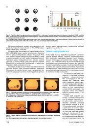
Processing of the Fuel CellOnce the basic ceramic structure of the anode was created, furtherfunctional layers of the fuel cell were deposited by screenprinting and followed by thermal processing. Temperature of firingof the electrolyte and cathode layers was adjusted experimentally.Four technological versions of the cell were fabricated. Table 2contains the specification of these versions.Tabl. 2. Technological versions of fuel cellsTab. 2. Wersje technologiczne testowanych ogniw paliwowychVersionFiring temperatureElectrolyte ESL 4481 Cathode ESL 4421I.1 1470°C 900°CI.2 1520°C 1000°CAdditionalprocessesI.3 1520°C 1000°C impregnation inbath Zr(NO 3) 4I.4 1600°C 1100°CIn version I.1 the electrolyte paste ESL 4481 containing 8 mol%yttrium stabilized zirconia (YSZ) was deposited twice with 200 meshscreen, first on the one side of the anode structure, and than onthe other, with separate drying of each layer at 900°C. The electrolytelayer was fired at 1470°C. In the next technological step, thecathode paste ESL 4421 containing lanthanum strontium cobaltferrite oxide (LSCF) was screen printed once through a 200 meshscreen on the surface of both electrolyte layers with separate dryingof each layer. The cathode layer was fired at 900°C. Silver gridwas screen printed with the silver paste on the surface of the cathodesto increase their electrical conductivity. Afterwards, anodeand cathode current collector electrodes were screen printed withsilver paste on both sides of the ceramic structure and then firedat 900°C. The edges of the ceramic fuel cell were sealed with hightemperature ESL glass C129 and fired at 950°C. Finally inlets forhydrogen and outlets for reaction products were drilled in the centreof the anode and cathode current collector electrodes.In the experiment labeled I.2, the electrolyte layer was firedat the temperature 1520°C, the cathode layer at the temperature1000°C.The experiment labeled I.3 contains, in comparison to versionI.2, the additional technological operation: the electrolyte layerwas after firing impregnated with a solution of zirconium salt Zr(NO 3) 4in order to improve the tightness of the electrolyte.Figures 2 shows a view of the complete fuel cell structure.Figures 3 presents the cross-section of the complete fuel cell.It is visible a green anode base with flow channels covered withoperating anodes on both sides, thin white layers of electrolytesand black strips of cathodes.Final technological operation in the process of fuel cell fabricationwas the reduction of the anode in the atmosphere of hydrogen.The complete fuel cell structure was inserted to a ceramictube of a furnace to which hydrogen diluted in nitrogen was deliveredwith a constant flow.The process of reduction was carried out at 500°C and lasted2 hours. As a result, the particles of nickel oxide NiO in the yttrium-stabilizedzirconia were reduced to metallic nickel Ni forminga porous Ni-YSZ structure. The anode changes the colourfrom green to black and becomes porous.Table 3 collects dimensions of the fuel cell model components.Tabl. 3. Geometrical dimensions of the cell componentsTab. 3. Wymiary geometryczne elementów ogniwa paliwowegoCellcomponentMaterialTotal thickness(fired)Anode base Ni/YSZ tape, 6 layers 0.780 mmOperating anode Ni/YSZ tape, 1 layer 0.130 mmElectrolyte 8YSZ, 2 prints 0.020 mmCathode LSCF, 1 print 0.021 mmentire ceramic structureflow channels60 × 19 × 1.2 mm0.270 mm wide,0.220 mm deepFig. 2. Top view of the complete fuel cell structure (from the left: cathodecurrent collector, silver grid printed on the surface of a cathode,anode current collector)Rys. 2. Widok z góry gotowej struktury ceramicznej ogniwa paliwowego(od strony lewej: elektroda zbierająca katodowa, siatka z pastysrebrowej na powierzchni katody, elektroda zbierająca anodowa)Fig. 3. Cross-section of the complete fuel cell (magnification 160×)Rys. 3. Przekrój poprzeczny kompletnego ogniwa (powiększenie 160×)16SEM observationsThe SEM of the complete test cell cross-section (technologicalversion I.4) is shown in Fig. 4. It can be observed the porous structureof the operating anode, dense electrolyte and the porouscathode. Pores visible inside the electrolyte layer are closed anddoesn’t affect the tightness of the electrolyte.Figures 5 shows the porosity of the anode after reduction.It can be seen the smooth dense particles of zirconia and spongyparticles of nickel.Figures 6 presents the surface of the electrolyte layer sinteredat 1600°C. It can be seen that the electrolyte layer is dense andnot permeable for gases.Electrical measurementsFigures 7 shows the test set-up used in experiments. It consistsof two flat platinum heaters deposited on the substrate of aluminanitrate AlN and embedded into thermal isolating foam. The heatersenable heating the cell up to 800°C. Hydrogen flow throughthe channels of the anode structure was maintained at 100 sccm.The active cell area is equal to 4 cm 2 .The fuel is provided to hot fuel cell via ceramic intermediateconnector, which thermally separates the fuel supply intake connectorfrom the hot fuel cell.<strong>Elektronika</strong> 4/<strong>2012</strong>


