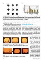
BGA676CSP132CSP84Profile P1 Profile P2 Profile P3Fig. 5. Cross-sections photographs of spherical solder joints made with use different soldering profilesRys. 5. Fotografie zgładów metalograficznych połączeń lutowanych wykonanych przy zastosowaniu różnych profili lutowaniaThe irregular shape of solder joints which can be observedin case of solder profile P1 in Figure 5 indicates not fully meltingand mixing of solder alloy from spherical lead of structurewith solder alloy from solder paste, and that solder joints areunacceptable (especially in case of CSP132 with solder profileP1. However, the quality of solder joints is much better in caseof solder profile P2 and P3. The elliptical outline of solder jointsindicates that during the soldering process, a phenomenonof fully melted spherical leads of package occurred, and thestructure package settled on the PCB’s surface, mostly in caseof solder profile P3.Among other things, thanks to microscopic observationsof cross-sections some imperfections in assembly process offunctional structures in BGA297 package (sign. ADSP-BF561SBBZ600) were identified. Although recommended by manufacturerof BGA structure construction of solder pads, and also onthe base of investigations both PCB’s solder pads and their sizewere modified. Solder pads were changed from solder maskdefined (SMD) to non-solder mask defined (NSMD), and alsothe size of pads was slightly increased. The entered modificationsallowed increasing the surface of solder pads by 25% andthanks to this it was possible to achieve significant improvementin the formation of good quality solder joints. Described modificationsof solder pads and the corresponding photographs ofmetallographic cross-sections from solder joints schematicallyare shown in Figure 6.Long-term reliability testsThe quality of solder joints directly influences their reliability, whichwas verified by long-term environmental tests. Initially the functionalelectronic packets were tested for functionality, and then packetswere placed in climatic chamber. After that, the functionalityof packets was verified once again. Normally, the packets areoperated in extremely variable environmental conditions (e.g. ina mine in Siberia), and because of that the functionality of electronicpackets has been studied according to the scheme shownin Figure 7, given by the Center for the Application of Hardwarefrom Tele and Radio Research Institute, which is a designer andmanufacturer of functional unit. Full-time of thermal stresses testwas about 106 hours, and after that the packets were exposed todump-heat test (-40 ±2°C; 93 ±2% RH) for 250 hours.Temperature [ C]100806<strong>04</strong>0200-20-40-60800 20 40 60 80 100 120Time [h]Fig. 7. Graph of environmental stresses testRys. 7. Wykres przebiegu długoczasowych narażeń klimatycznycha)b)Fig. 6. Modifications of solder pads for BGA297 assembly: a) schematicconstructions, b) cross-sections photographs of solder jointsRys. 6. Modyfikacja pól lutowniczych przeznaczonych do montażustruktury w obudowie BGA297: a) konstrukcja, b) fotografie zgładówmetalograficznych24The results of realized long-term reliability tests shows on thegood quality of solder joints formed in mixed assembly process.All verified functional units were characterized by a correct functionalityboth before and after environmental stresses.Influence of mixed assembly processparameters on quality of solder jointsThe realized investigations shows no significant influence on thequality of solder joints both protective coatings of solder pads(Ni/Au, immersion Sn), as well as solder paste content (stencilthickness). However, it was observed some influence of solderingprofile type. It should be noticed that the correct solder joints wereobtained using all three selected profiles (P1, P2 and P3), but thebest results were obtained in case of P2 and P3 profiles. Solder<strong>Elektronika</strong> 4/<strong>2012</strong>
joints made under these conditions were characterized by themost regular shape (no wrinkled spherical surface), which indicatesto complete melting and mixing of the alloy contained in thesolder paste with the alloy from component leads. Moreover, thesesolder joints were characterized by a smallest amount of voids– less than 5%. In comparison, solder joins made with profile P1have voids about 7–9%.Because it is very possible to exist both leaded as well aslead-free components in the same electronic packet, it is recommendedto use soldering profile approximated to profile P2,where the maximum soldering temperature of the whole electronicpacket does not exceed 235°C. Simultaneously, the minimumtemperature of spherical leads soldering (for BGA or CSP)should be about 220°C or higher.Guidelines for mixed assembly processThe achieved results of realized investigations allows formattingthe guidelines for assembly of electronic packets in mixed technology.Below, in pointed form, the basic recommendations arecollected:– it is recommended to use leaded solder paste signed by symbolHM-1 RMA V16L (Sn62Pb36Ag2) from Almit company;– the soldering process can be made using PCB with any protectivecoating of solder pads (Ni/Au or immersion Sn), undercondition of guaranty of good solderability for the leaded technology;– if it possible the PCB should not consist in their design thesolder pads defined by solder mask;– the thickness of stencil for screen printing of solder paste mustbe compatible with the general recommendations for leadedassembly technology for whole-mounted electronic packet;– it is recommended to proceed to achieve temperature-timecourse corresponded with the proposed soldering profile P2(see Fig. 2).SummaryThe realized investigations allowed to elaborate of the main recommendationsto making mixed assembly process of electroniccomponents with hidden leads under the package. Long-term reliabilitytests have not shown the creation of solder joints defects.Selected leaded solder paste HM-1 RMA V16L (Sn62Pb36Ag2)from Almit company, despite applying the widely varying of solderingprofiles, very well fulfills its task for assembly both multileadstructures, as well as other electronic components used inSMT assembly.The Centre of Advanced Technologies has already realizedthe mixed assembly process of electronic devices for external customers(e.g.: Techlab2000; EDO Exclusive Digital Audio, MilitaryInstitute of Communication) and until now there were not observedany defects of solder joints of BGA and CSP packages.The scientific work funded from funds on the ITR statutory workin 2010 as the research project signed by No. 130-02430013.References[1] Bukat K., Hackiewicz H.: (2007). Lead-free Soldering., Wydawnictwobtc, ISBN 978-83-60233-25-2, Warszawa (in Polish).[2] Borecki J.: (2006). Manufacturing of high tech PCBs in Tele and RadioResearch Institute. <strong>Elektronika</strong> XLVII, 8/2006, 11–14 (in Polish).[3] RoHS and WEEE directives (http://www.rohs-weee.pl/index.php)[4] Kozioł G., Araźna A., Stęplewski W.: (2010). The Characteristics ofan Electroless Nickel/Immersion Gold Plated PWB Surface Finishand the Quality of BGA Solder Joints. Plating and Surface Finishing.97(1), 39–45.[5] Stęplewski W., Kozioł G., Borecki J.: (2008). Influence of stencil designand parameters of printing process on lead-free paste transferefficiency. XXXII International Conference of IMAPS – CPMT IEEEPoland, 21–24 September, Pułtusk, CD-ROM.[6] IPC-A-610 rev. D – Acceptability of Electronic Assemblies. (20<strong>04</strong> November).[7] Kościelski M.: (2008). Usage of X-ray inspection for detecting solderingfailures. <strong>Elektronika</strong> XLIX, 3/2008, 88–89 (in Polish).Fabrication and properties of multilayer capacitorswith multicomponent ferroelectric dielectric(Wytwarzanie i właściwości wielowarstwowych kondensatorówz wieloskładnikowym ferroelektrycznym dielektrykiem)dr Jan Kulawik, dr inż. Dorota Szwagierczak<strong>Instytut</strong> Technologii Elektronowej, Oddział w KrakowieMultilayer ceramic capacitors can offer small size, high capacitance,stable temperature characteristics, high reliability and lowcost [1–8]. The successful attainment of these features is stronglydependent on applied dielectric materials.The MLCC structure manufactured in LTCC process consistsof alternate dielectric layers and metallic electrodes in parallelconfiguration. High dielectric constant, small thickness and largenumber of dielectric layers are factors determining high volumetricefficiency of a multilayer capacitor. The progress in tape castingand LTCC technology has made it possible to produce hundredsof very thin dielectric layers with a thickness diminished down to 3µm. The early dielectric formulations are based on BaTiO 3whichresulted in necessity of the use of expensive platinum or goldplatinum internal electrodes.Application of sintering aids lowering BaTiO 3firing temperaturedown to 1150°C allowed utilization of cheaper palladium-silverelectrodes. A further decrease in this temperature making possiblethe use of Ag electrodes requires excessive amounts offluxes and causes detrimental diminishing of dielectric constantof BaTiO 3ceramic.One of the best solutions overcoming these problems is theintroduction of relaxor compounds with perovskite structure anda general formula of Pb(B’B”)O 3(B’=Mg, Zn, Fe; B”=Nb, Ta, W).High and broad maxima of dielectric permittivity along with lowsintering temperature and ability to form thin layers are advantagesof capacitor dielectrics containing these materials.In this work the multicomponent composition of dielectricwas tailored to attain a few purposes determining processingconditions and desired properties of multilayer capacitors,such as:● low sintering temperature suitable for cofiring with cheap Agelectrodes● high permittivity near room temperature● low temperature coefficient of capacitance over a wide temperaturerange● high resistivity.<strong>Elektronika</strong> 4/<strong>2012</strong> 25


