BASIC OPERATION GUIDE 10ZiG 360 CE Wireless Digital Tablet ...
BASIC OPERATION GUIDE 10ZiG 360 CE Wireless Digital Tablet ...
BASIC OPERATION GUIDE 10ZiG 360 CE Wireless Digital Tablet ...

You also want an ePaper? Increase the reach of your titles
YUMPU automatically turns print PDFs into web optimized ePapers that Google loves.
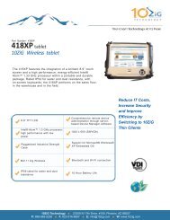
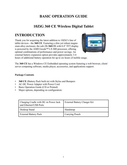
INTRODUCTION<strong>BASIC</strong> <strong>OPERATION</strong> <strong>GUIDE</strong><strong>10ZiG</strong> <strong>360</strong> <strong>CE</strong> <strong>Wireless</strong> <strong>Digital</strong> <strong>Tablet</strong>Thank you for acquiring the latest addition to <strong>10ZiG</strong>’s line oftablet devices - the <strong>360</strong> <strong>CE</strong>. Featuring a slim yet robust magnesiumalloy enclosure, the sub-2lb <strong>360</strong> <strong>CE</strong> with 8.4” TFT displayis powered by the AMD Geode LX 800 processor, offeringoptimal combinations of performance and power savings. Anexternal battery expansion option provides approximately 3-4hours of additional battery operation for up to six hours of mobile usage.The <strong>360</strong> <strong>CE</strong> has a Windows <strong>CE</strong> Embedded operating system featuring a web browser, client/server computing software, media player, accessories, and applications support.Package Contents• <strong>360</strong> <strong>CE</strong> (Battery Pack built-in) with Stylus and Bumpers• AC-DC Power Adapter with Power Cord• Basic Operation Guide (CD or Printed)• Major options, depending on configuration:Charging Cradle with DC-in Power Jackand Ethernet/USB PortsDesktop StandExternal Battery PackExternal Battery Charger KitHandstrapCarrying Pouch1
Button Functions with Windows <strong>CE</strong> Operating SystemButton Description Action1 Power Button Push/release typically enters Standby mode, or Push/release exitsStandby mode or restarts device (software dependent).Push and hold (over 4 seconds) invokes hardware shutdown.2 First in group of four Programmable, Launch soft (on-screen) keyboard (Default)3 Second in group of four Launch Internet Browser4 Third in group of four Programmable, Launch RDP (Default)5 Fourth in group of four Programmable,Desktop (Default)6 Left edge of button Programmable7 Right edge of button Programmable8 Upper edge of button Programmable, Brightness Increased (Default)9 Lower edge of button Programmable, Brightness Decreased(Default)2
Precautions• Always exercise care when operating and handling the <strong>360</strong> <strong>CE</strong>.• Do NOT apply excessive pressure to the display screen.• We recommend using the Stylus provided to keep the screen clean.• Avoid prolonged exposure of the display panel to direct sunlight or other heat source. Whereverpossible, the <strong>360</strong> <strong>CE</strong> should face away from direct light to reduce glare.• If the AC-DC power adapter is used to recharge or power the device, do NOT use any AC-DCadapter other than the one provided with the device or acquired from the manufacturer or itspartners.• In the unlikely event that smoke, abnormal noise, or strange odor is present, immediatelypower the <strong>360</strong> <strong>CE</strong> off and disconnect all power sources. Report the problem to your deviceprovider immediately.• Never attempt to disassemble the <strong>360</strong> <strong>CE</strong>, as this will void the warranty.THE <strong>360</strong> <strong>CE</strong>Basic FeaturesThe <strong>360</strong> <strong>CE</strong> wireless tablet integrates a bright and responsive touch display, a USB port, a PCM-CIA slot, and embedded networking elements such as wireless LAN and Bluetooth. The primarydevice is complemented by a suite of accessories, including battery expansion, docking cradles,and carrying cases, for a comprehensive user experience.A <strong>360</strong> <strong>CE</strong> typically integrates an 802.11b/g or 802.11a/b/g wireless LAN (WLAN) adapter thatmay connect to other wireless devices or access points. If your <strong>360</strong> <strong>CE</strong> does not come with such anetwork adapter, please consult your device provider to establish the desired network connectivity.<strong>OPERATION</strong>Internal Battery Switch - IMPORTANT!To prevent battery drain during shipping and extended storage, the internal battery may be turnedoff. To turn on the internal battery, push the battery button switch (on the back panel) to the “up”position (see page 2 for photo/location). The internal battery pack has to be turned on for it tooperate, be charged, and for the optional external battery pack to function.Powering ON and OFFTo activate the <strong>360</strong> <strong>CE</strong>, push and quickly release the Power Button to the left of the front bezel.The display will come on in a few seconds. To put the <strong>360</strong> <strong>CE</strong> in Standby mode, push and quicklyrelease the Power Button. To turn the <strong>360</strong> <strong>CE</strong> off for extended storage, power off the devicesafely using any software function that “shuts down computer” provided in the software operatingsystem.3
NOTE: The battery packs shipped with your device may be low in power - please use the AC-DCadapter with the <strong>360</strong> <strong>CE</strong> when setting up the device for the first time to fully charge the internalbattery pack. You may charge the external battery pack with it attached to the <strong>360</strong> <strong>CE</strong>, or with theoptional external battery charger kit.NOTE: When the battery pack(s) is (are) charging, the blue-colored Battery LED should blinkslowly. If plugging in the AC-DC adapter does not trigger this blinking activity and the LED staysdark, the battery pack(s) may have been substantially drained. Try unplugging/replugging the AC-DC adapter to the <strong>360</strong> <strong>CE</strong> a few times to activate the charging process.NOTE: To conserve power, use (push and quick release) the Power Button to put the device in“Standby” mode while not in use. Pushing briefly on the same button will wake up the systemwithin seconds.NOTE: Avoid using the Power Button (“hold 4+ seconds” feature) to turn off the device--thisform of hardware shutdown is intended to be a means of recovery from device lockups, and not asnormal operation.Start UpIf the power up (from Standby or otherwise) is successful, the appropriate interface will be displayedafter a launch sequence of several seconds. The wireless LAN connection may take 10-15seconds to be established.Configuring the <strong>360</strong> <strong>CE</strong>The device may be configured using the utilities and methods dictated by the software operatingsystem. The <strong>360</strong> <strong>CE</strong> should be configurable for various properties such as user profiles, networkfeatures, and several system elements.Changes to the <strong>360</strong> <strong>CE</strong> must be saved using the Save Settings option in the control panel or whenthe unit is rebooted they will be lost.Access the User Control Panel by selecting Start - > Settings -> Control Panel -> Save Settingsand check to Save Current Settings.4
CalibrationThe touch display for the <strong>360</strong> <strong>CE</strong> is calibrated before shipping. In the event that the calibrationhas been modified or is unsatisfactory, the respective calibration routines (e.g., PenMount (PM)for Windows <strong>CE</strong>) to calibrate the touch interface may be used. Such applications are typicallyexecuted through touch input via Stylus or through mouse click via a USB mouse.<strong>Wireless</strong> Networking<strong>Wireless</strong> LANThe <strong>360</strong> <strong>CE</strong> is delivered with an embedded (user-inaccessible) 802.11a/b/g WLAN adapterequipped with a hidden custom antenna. This embedded interface is supplemented by a useraccessiblePCMCIA slot for use with third-party network adapters or peripherals.Through the support of typical WLAN adapters, the <strong>360</strong> <strong>CE</strong> should be able to detect all 802.11access points in the vicinity for you to select the access point of your choice for connection.To connect to a network that does not have security enabled, double click on the desired networkconnection and the tablet will connect. To connect to a network that has security enabled, doubleclick on the network or click on the network and select connect to configure the connection.The SSID and WEP (if enabled) parameters on the <strong>360</strong> <strong>CE</strong> and the access points have to match.The SSID is case-sensitive and it is recommended that you enable WEP encryption (or advancedalternatives) for secure access.When WEP is enabled, you may need to consult your network administrator or your networkingequipment literature to properly configure associated settings such as Authentication mode, etc.Refer to the access point operating manuals for setting up the 802.11 access points.BluetoothThe <strong>360</strong> <strong>CE</strong> features a built-in Bluetooth adapter that operates on the Microsoft Windows Bluetoothprotocol. The Bluetooth configuration application is invoked from the Windows <strong>CE</strong> EmbeddedControl Panel. Follow the instructions and options provided within the application toconfigure and invoke Bluetooth connectivity with the corresponding peripherals.NOTE: Bluetooth devices or accessories that are not compatible with the Microsoft WindowsBluetooth protocol may not work with the <strong>360</strong> <strong>CE</strong>.5
Button ManagementWhen supported by software, many of the hard buttons on the <strong>360</strong> <strong>CE</strong> are programmable to performa function of the user’s choice. To activate the button re-assignment application, invoke theButton Settings ICON, in the Windows <strong>CE</strong> Embedded Control Panel.Brightness ControlWhere supported by device firmware and software, a hard button (Button 8) may be engaged tomanipulate the display brightness. Press the Button 9 to lower the brightness of the screen. Whenselecting Brightness from the control panel, the system screen will display a Brightness controlsection with a slide bar to increase or decrease brightness that can be activated with the stylus.Battery and Power ManagementThe <strong>360</strong> <strong>CE</strong> is equipped with an internal Li-Ion battery pack that is capable of supporting approximately1.5-2 hours of continuous operation. The period of continuous operation can be extendedby approximately 3-4 hours with the external battery pack that clips (hot-pluggable) onto the backof the device. The period between battery recharges can be significantly lengthened by putting thedevice into Standby mode through the Power Button (see Buttons Function Table) whenever thedevice is not in use. Based on the <strong>CE</strong> Operating System the <strong>360</strong> <strong>CE</strong> may be configured to entervarious power-saving modes via the Power Button or through timed entry.Optional Desktop CradleThe <strong>360</strong> <strong>CE</strong> is complemented by an optional Desktop Cradle for support, pass-through charging,and connection to a range of USB peripherals, including keyboard and mouse. The Cradle offersthe following interfaces: a DC-in port for the AC-DC adapter, an Ethernet port, and USB ports.Always seat the <strong>360</strong> <strong>CE</strong> securely onto the cradle. The cradle must be powered by the AC-DCadapter for the Ethernet and USB ports to function. The battery packs on the <strong>360</strong> <strong>CE</strong> may berecharged by connecting the AC-DC adapter directly to the DC-in port on the <strong>360</strong> <strong>CE</strong> or throughthe DC-in port on the Desktop Cradle while the <strong>360</strong> <strong>CE</strong> is docked to the Cradle.6
USING THE <strong>360</strong> <strong>CE</strong>Memory ConfigurationThe <strong>360</strong> <strong>CE</strong> is available in various memory configurations. The standard RAM/Storage capacityis 256MB/64MB (RAM/Storage).NOTE: Users may supplement their embedded flash memory space with USB-based peripheralssuch as USB flash disks, USB disk drives, etc.Peripherals SupportThrough its USB port and PCMCIA slot, the <strong>360</strong> <strong>CE</strong> supports a wide range of peripherals. Theseperipherals are applicable for software installation, applications storage, data storage, and systemsoftware recovery and updates. The <strong>360</strong> <strong>CE</strong> is also compatible with custom mountable cradleoptions. These securable and mountable cradle options provide an interface to VESA mounts andarms, and to ports that may include USB, Ethernet and pass-through power.Remote ManagementThe <strong>360</strong> <strong>CE</strong> can be centrally managed for emulation sessions by using the management program.7
Configuring EmulationOn the desktop you will find a folder called Administrator. Open the folder or double click on itto start the configuration.Select Add and then scroll down to select TN5250e Display8
NOTE: Please be aware that the screen shots for emulation below may not match exactlywith the <strong>CE</strong>.NET tablet.There are several options for the connection type in the list - for the 5250 display session selectTN5250e Display.Enter the Host Name or IP address of the AS/400. Port Number is the default port for telnet. If thisis changed, the AS/400 must be configured to accept connections on the non-standard telnet port.9
The connection name is the name of the session on the thin client and the device name is the nameof the device description on the AS/400The wizard will auto detect the attached keyboard. If a <strong>10ZiG</strong>122 keyboard is attached, it willdefault to122 keys <strong>10ZiG</strong>. If a standard 101/102 keyboard is attached it will default to 101 Terminal(right control = enter). For the enter key to be enter using a 101/102 keyboard, select 101PC.10
The connection will appear in the connection manager, as an ICON on the desktop with the titleEmulator.To modify the connection, highlight the connection name and select edit.To change startup options select the connection and select starup at the bottom of the Display SessionPropertiesDisplay Session Properties - Connection TabConnection tab allows for changes to the host name/IP address and the port number. Also allowsfor session changes such as connection name, device name and device type. For advancedoptions, select Advanced options....Enable Automatic reconnection - when enabled and the network connection is lost the unitattempts to reconnect the session - this works best when the connection between the unit and thehost is local and does not go through a router.Enabling Keep Alive each (sec) causes the unit to send a ping periodically to the AS/400 thuskeeping the connection alive even when the unit is idle. Depending on the router type you mayneed to change the type to Telnet NOP.11
Note: Currently the iSeries only supports Telnet NOP.Bind local TCP port to fixed value is the port the telnet session communicates back to the unit. All5250 session will by default communicate to the AS/400 on port 23.Startup Macro: Do no check unless directed to do so by technical support.12
Display Session Properties - General TabAllows for changes to Code Page,Keyboard Language,Keyboard Type, Cursor options, Ruleroptions, Print Screen Configuration and other Miscellaneous options.Font options are CM Terminal or Courier NewCursor options are Blinking Block, Blinking Line, Non-Blinking Block, or Non-Blinking Underline.Ruler options are Cross Ruler, Horizontal Ruler or Vertical Ruler.Miscellaneous options can be turned on and off by checking or unchecking associated boxes.13
Printscreen menu option action determines if the print screen key can be set to Local Print, Printthrough the Host or Function Disabled.14
Printer type is limited to built in drivers, select the closest match. If in doubt, try Generic/TextOnly or use Host Print Transform.To edit the code page select edit to the right of Code Page.Code page is the traditional IBM term used for a specific character encoding table: a mapping inwhich a sequence of bits, usually a single octet representing integer values 0 through 255, is associatedwith a specific character.5250/3270 communication is encoded using EBCDIC. The code page is a lookup table whichconverts EBCDIC to ASCII to display and/or print the data.For printer sessions, sometimes the AS400 applications will send special EBCDIC characters tocontrol the printer. (ie - specifically for barcodes). In this case it may be necessary to modify thetranscode table to select the proper ASCII code required by the printer.For instance an application may send an EBCDIC 'B0' as the start barcode command. By defaultthis is mapped to an ASCII 0x5e - '^'. Sometimes the barcode printer will require an ASCII 0x24 -'$'. In this case you can edit the transcode table entry for EBCDIC 'B0' and change it from 0x5e to0x24.When editing the transcode table the vertical rows are the MSB of the EBCDIC code, while thehorizontal cols are the LSB of the EBCDIC code. So for EBCDIC 0xB0, go to the B0 row and the00 column.15
Remapping the KeyboardSelect Edit to the right of the keyboard type to edit the keyboard.To modify a key, select the key with the mouse. Action will change accordingly. Select Edit andthen change the action to the desired command.16
Display Session Properties - Attributes TabTo change the column separator character select the Edit option to the right of the Column Separator.18
Display Session Properties - Hot Spot TabThis option allows you to Add, Edit or Remove Hot spots.Example of hot spot designed to run a macro that signs the user off of the host:Record a macro by selecting the red circular ICON. Type the commands for the macro and saveit. For this example a macro is recorded that types signoff and selects enter. Macro name is savedas signoff.19
Hot Spot Key Word is TENZIG - the system name that is displayed in the upper right corner ofthe display.Text String is left blank.Selected Action is Recorded Key Sequence.Action is the name of the created Macro20
When signed on to the host, double click on TENZIG in the upper right hand of the screen and themacro named signoff will run.23
Display Session Properties - Keypad TabThis option allows to change the options on the keypad that can be displayed in a 5250 sessionYou can Add, Edit or Remove commands on the keypad buttons.24
Display Keyboard Pad displays at the bottom of the 5250 screen.25
Display Session Properties - Sign On TabTo bypass the signon screen and signon automatically, complete the screen below with the propercredentials.NOTE: The system value QRMTSIGN on the iSeries must be set to *VERIFY for this to work.26
Display Session Properties - Advanced TabAppearance - option allows to show menu and toolbar oride it. Use the drop down Status Bartype: to change the status bar.For a 5250 session that looks more like a terminal session, uncheck “Show Menu and Toolbar”and select “Classic” as the Status Bar type.Security Configuration - option allows to enable or disable specific functions on the toolbar.Host Device Connection - check to allow the use of a default host name if there is a device conflicterror.Miscellaneous - do not change any of these options unless instructed to do so by a <strong>10ZiG</strong> technicalsupport engineer.27
SPECIFICATIONSDisplayDisplay Resolution8.4” Hi-Brite TFT LCD with resistive touch andoutdoor-viewable option800 x 600 (SVGA)Processor AMD Goede LX 800Memory (flash)Memory (RAM)Software Operating SystemsStorageStylusProtective Bumpers64MB256MBWindows <strong>CE</strong>.NETInternal flash module; USB HDDNon-electronic tipTwo rubber bumpers with optional adjustablehand strap, adds drop protectionNetwork Interface PCMCIA; USB: Integrated <strong>Wireless</strong> 802.11;Bluetooth build-inInput and Control ButtonsInput/Output PortsEnclosureAC/DC adapterPower CordsBattery Packs (Lithium-Ion)Desktop Cradle(Optional)Desktop Stand (Optional)Dimensions (H x W x D)Base WeightRegulatoryFour (4) front buttons; One (1) oval 4-way; OnePower (left edge); One “Trigger” (right edge);Internal battery control switch12V DC-in Jack; Microphone-In; Headset jack;USB 2.0 portMagnesium-Aluminum alloyInput: 100-240VAC, 1.2A; Output: 12VDC,3.5ANorth America, EU, UKInternal (14W); Optional external (28W, 0.5lb),and optional tethered pouch (72W, 1lb)Pass-through for power; Ethernet, USB 2.0 portsAluminum parking stand7.9 x 9.6 x 0.8 (in); 200 x 240 x 18 (mm)1.9 lbs (0.86 kg)FCC Class B, <strong>CE</strong>, UL, RoHS compliant28
Operating TemperatureHumidity0° - 40° C0% - 90% non-condensing29
<strong>10ZiG</strong> Technology LimitedHeadquarters US23309 N 17th Drive - Ste 100Phoenix, AZ 85027Phone 866-864-5250 • Fax 623-516-8697support@10zig.comsales@10zig.comwww.10zig.comHeadquarters UK10 ZiG Technology LimitedAction Business CentreSwan StreetLeicester LE3 5ATPhone 44 1509 276252 • Fax 44 1509 276253support@10zig.eusales@10zig.euwww.10zig.euMay 7, 200930